Note the update below explaining how many of the constructs in this series are dated. But the series is still an interesting study on what can be accomplished with a limited set of primitive building blocks
The VCV Rack Fundamental plugin has a very limited, yet very capable set of basic modules. Often times we go to 3rd party plugins for many basic or not so basic functions. But sometimes there are ways to do the same using just the Fundamental modules - it just may not be obvious.
This topic is a place to share saved selections (mini patches) built entirely out of free VCV modules that implement a specific function that typically is handled by a single module by 3rd party plugins. This is not intended to be finished works of art, but rather a collection of utilities that can be used to create larger patches. I may however include some larger patches that demonstrate how some of the constructs can be used.
Timing is critical for many patch functions. When performing an operation within a single module, it is easy to keep the timing intact. But the job is more difficult when patching multiple modules together because each patch cable introduces 1 sample delay. Great care has been taken to ensure multiple input signals stay in sync with each other as they course through the construct so the correct output is produced. I try to call out the few cases where this was not possible. I also document how much sample delay is introduced from the input to the output so that delays can be compensated for when used in a larger patch.
Each construct includes one or more NOTES modules with complete but terse documentation on how to use the construct.
This opening post serves as a table of contents, grouped by categories, with links to the specific modules.
Feel free to post your own construct that uses only free VCV modules. I may add a link to your construct to the table of contents.
Math
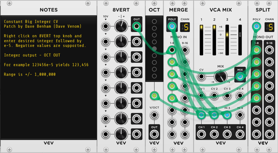
- Constant Big Integer CV - range is +/- 1,000,000
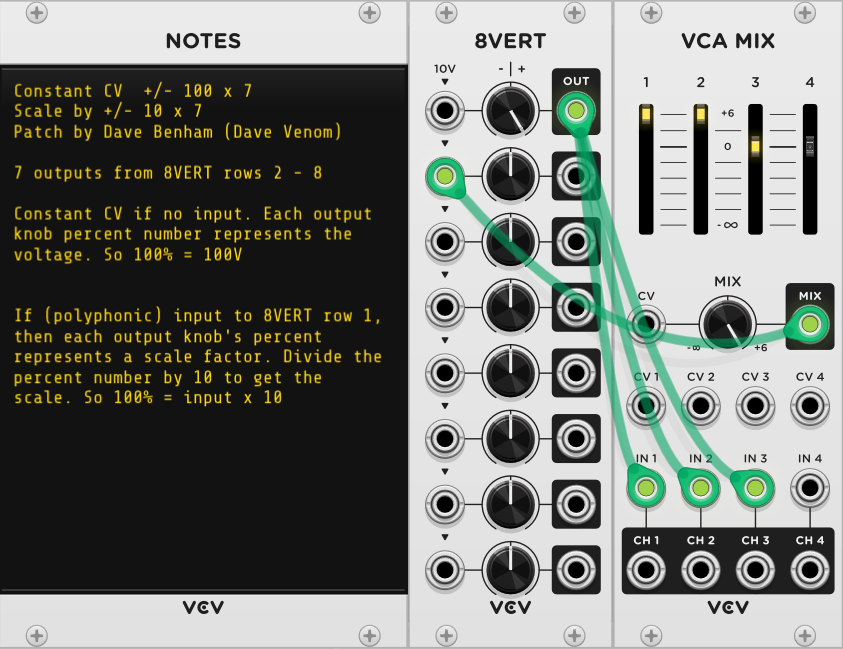
- 7 x Constant CV +/- 100 or Scale input +/- 10
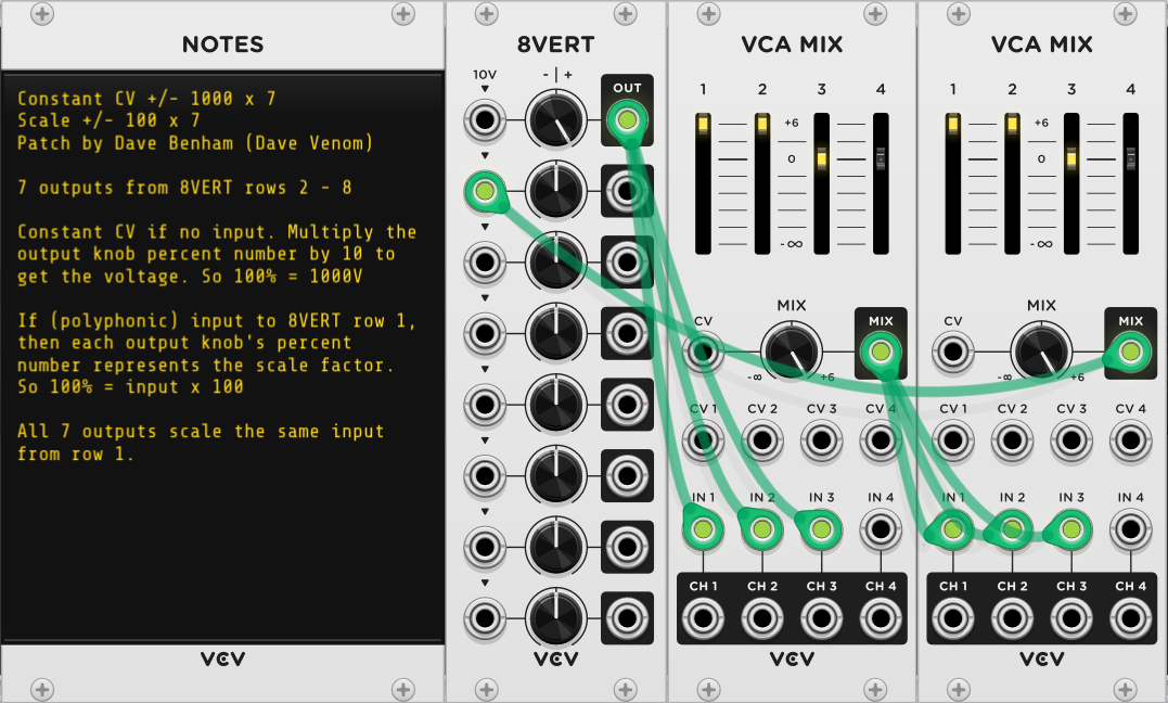
- 7 x Constant CV +/- 1000 or Scale input +/- 100
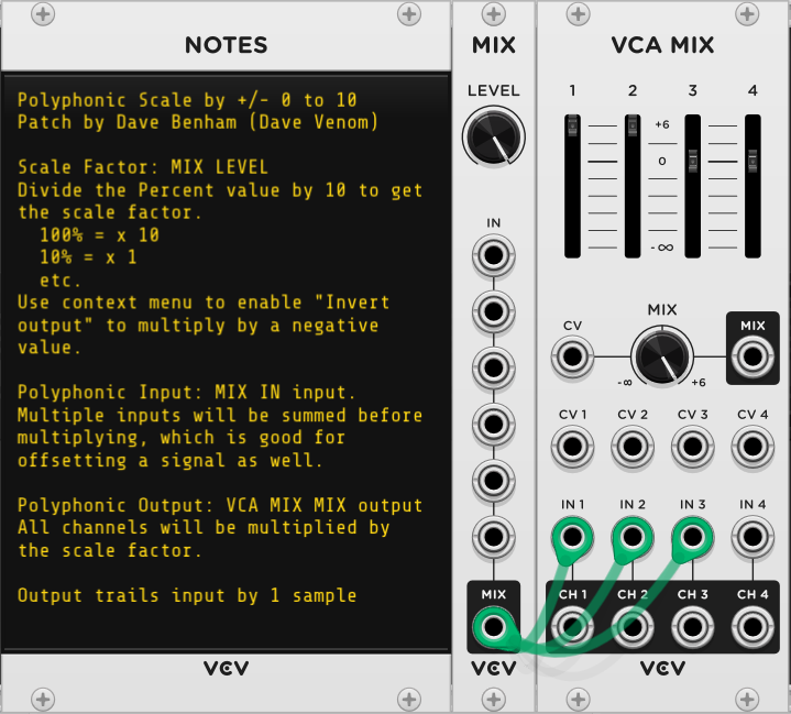
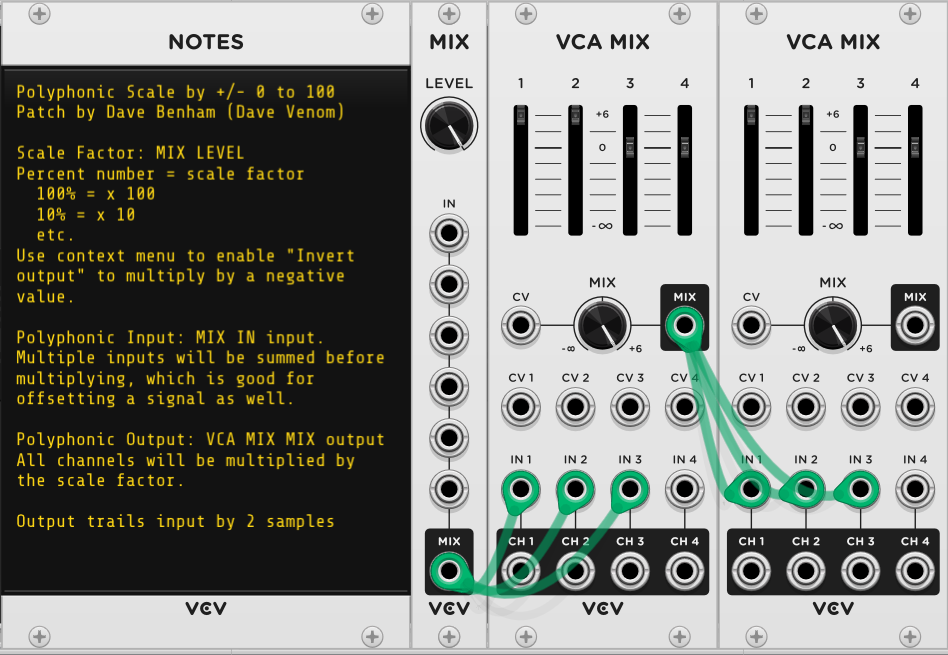
- Polyphonic Scale Input +/- 10
- Polyphonic Scale Input +/- 100
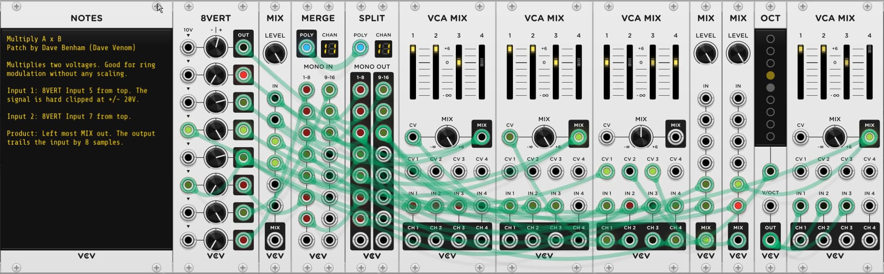
- Multiply A x B (unscaled ring modulation)
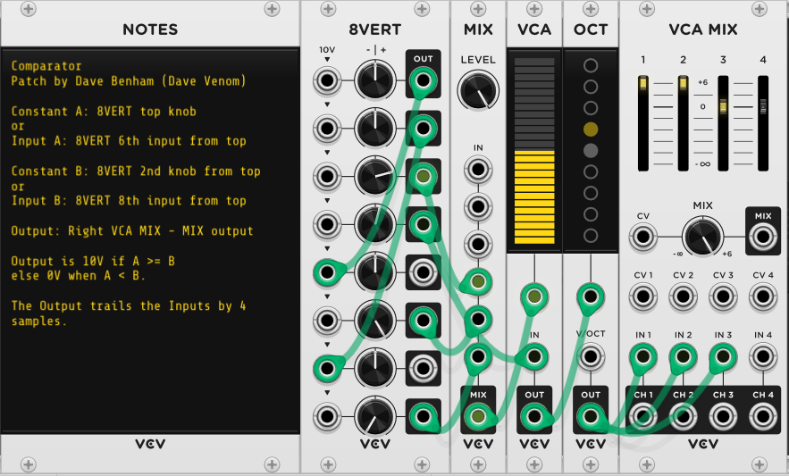
- Comparator Output 10V if A >= B, 0V if A<B
- Polyphonic Comparator
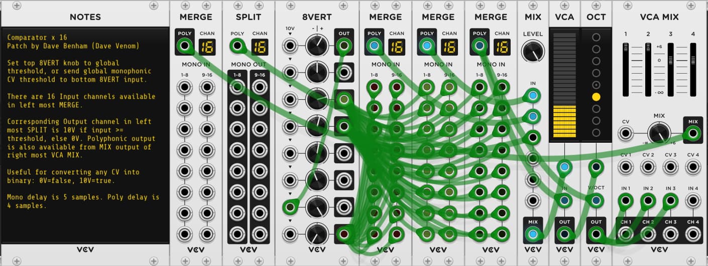
- Comparator x 16 16 independent comparators
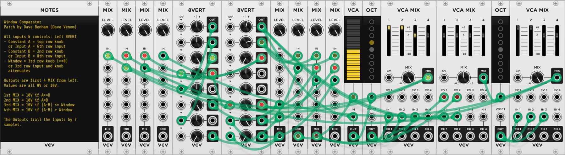
- Window Comparator Independent outputs: [A>=B, A<B], [A=B or A<>B within Window tolerance]
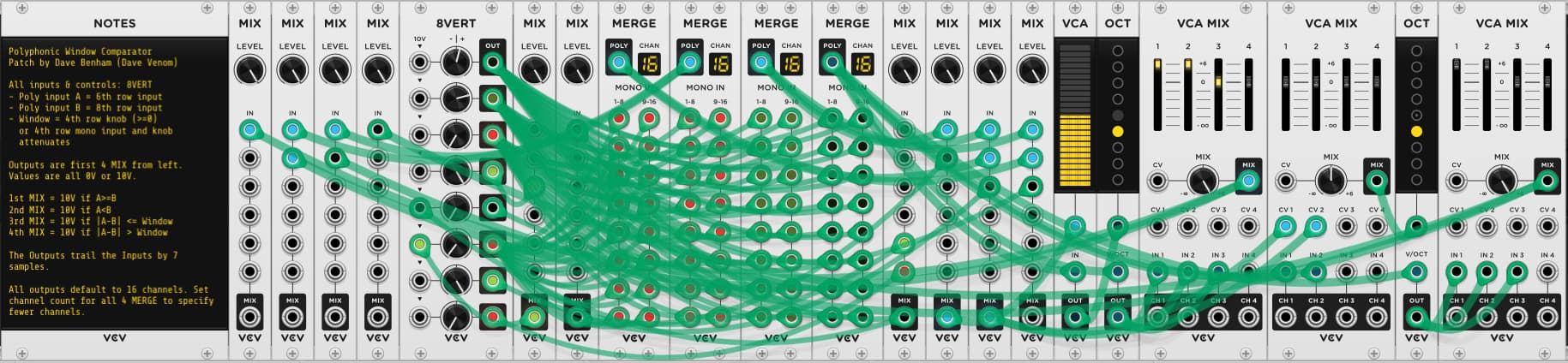
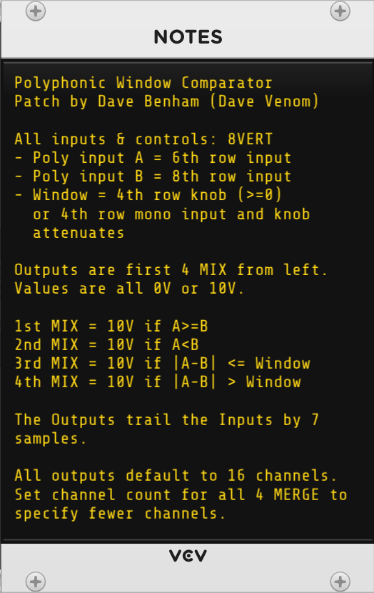
- Polyphonic Window Comparator
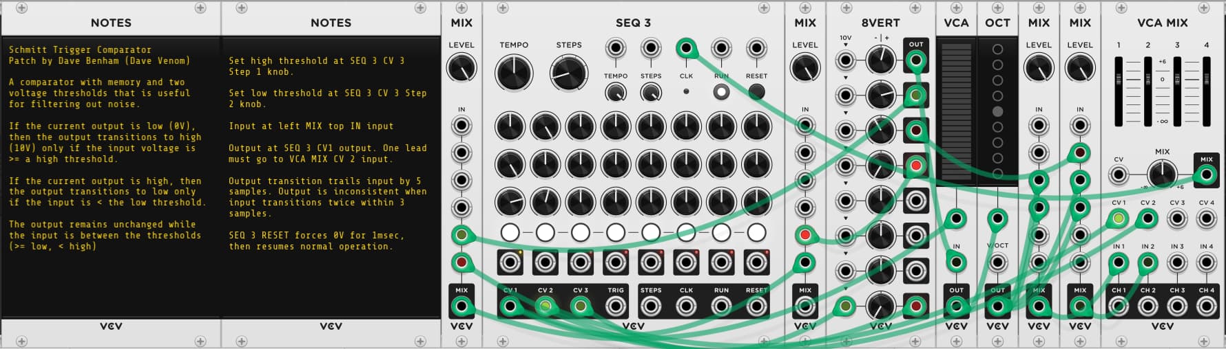
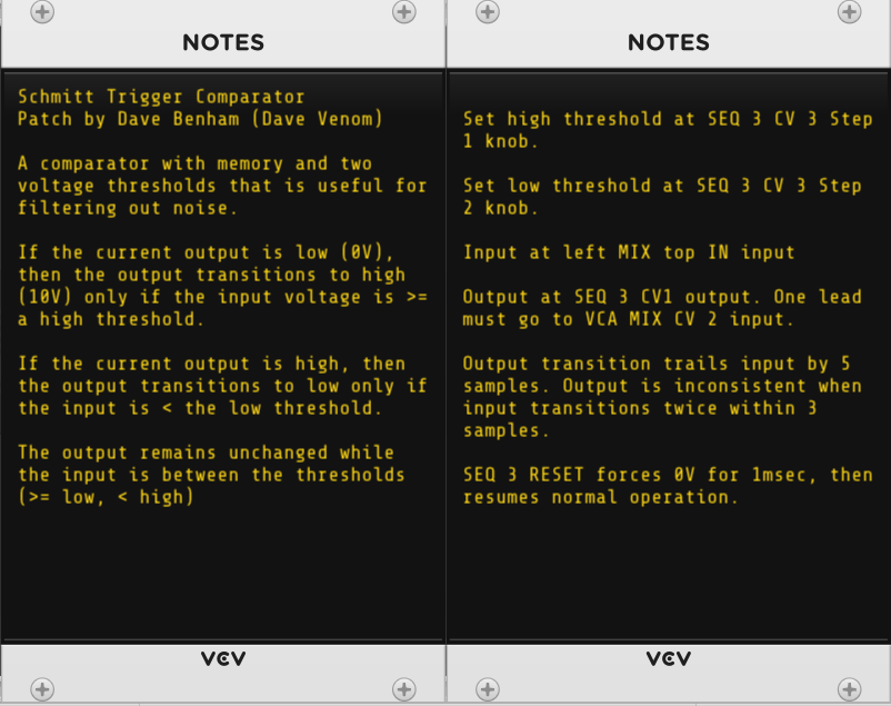
- Schmitt Trigger Comparator Noise resistant comparator with two thresholds and memory
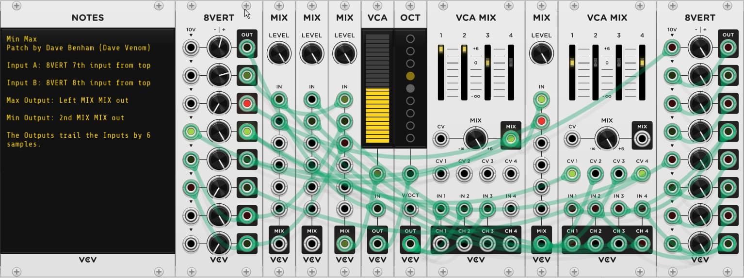
- Min - Max Take two inputs and send the minimum to one output, and the maximum to another
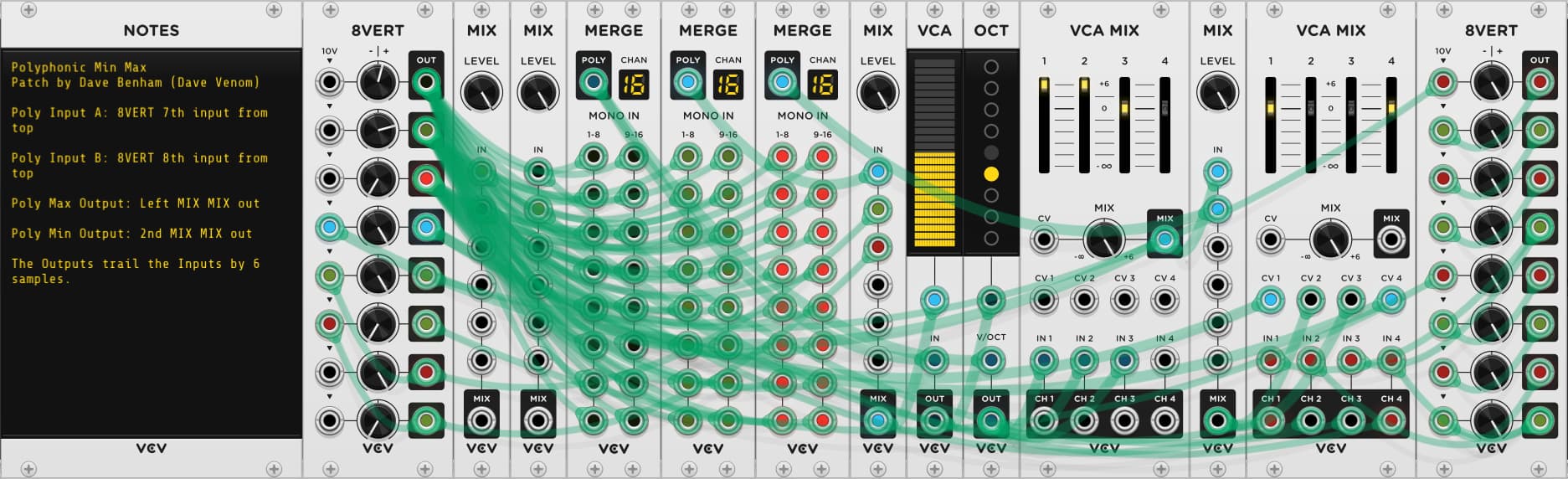
- Polyphonic Min - Max
Logic: 10V = TRUE, 0V = FALSE
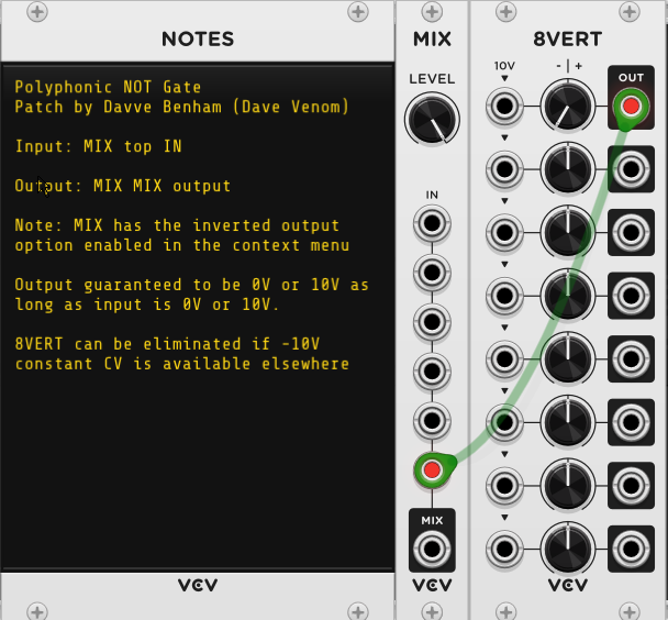
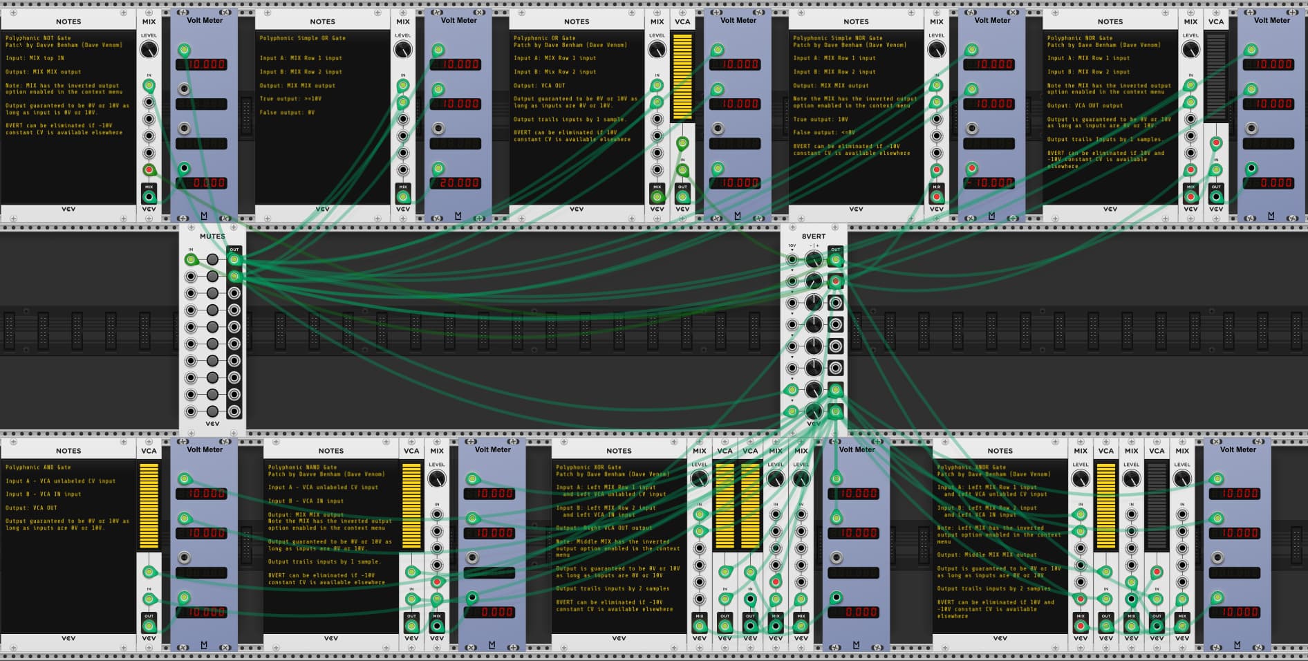
- Polyphonic NOT Gate
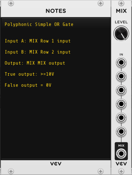
- Polyphonic Simple OR Gate - (TRUE output >= 10)
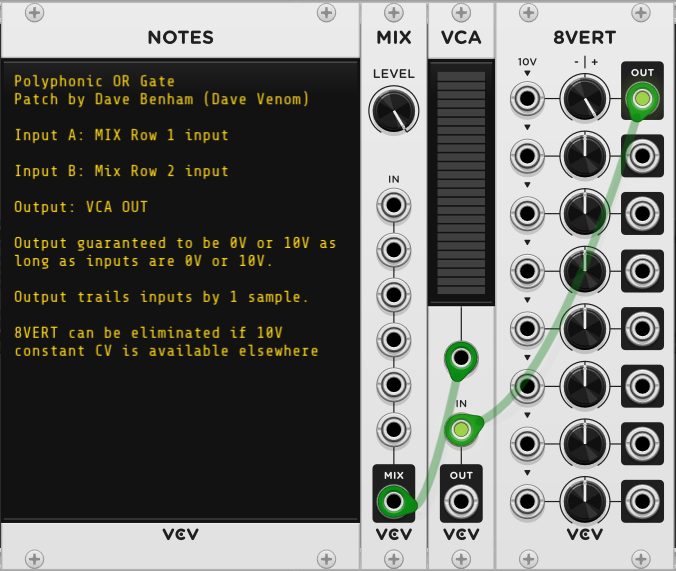
- Polyphonic OR Gate
- Polyphonic Simple NOR Gate - ( FALSE output <= 0)
- Polyphonic NOR Gate
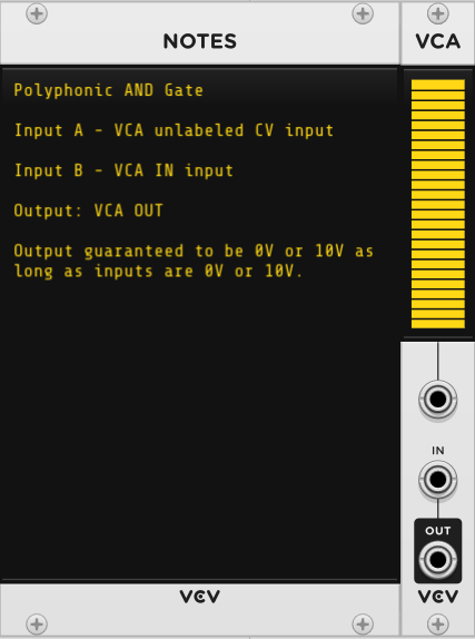
- Polyphonic AND Gate
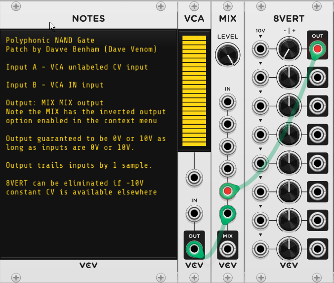
- Polyphonic NAND Gate
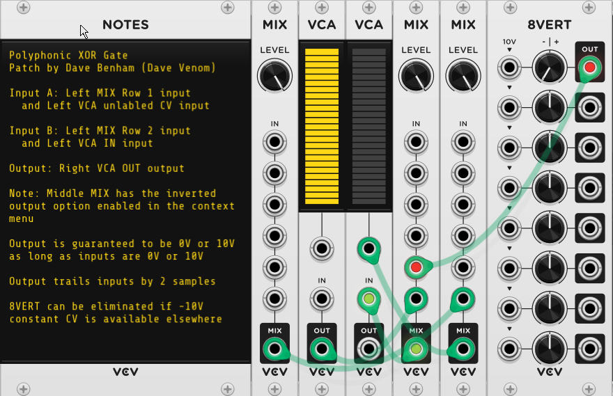
- Polyphonic XOR Gate
- Polyphonic XNOR Gate
Clock Modulators / Frequency Dividers
- Chainable 3 Stage Flip Flop - Resets ON
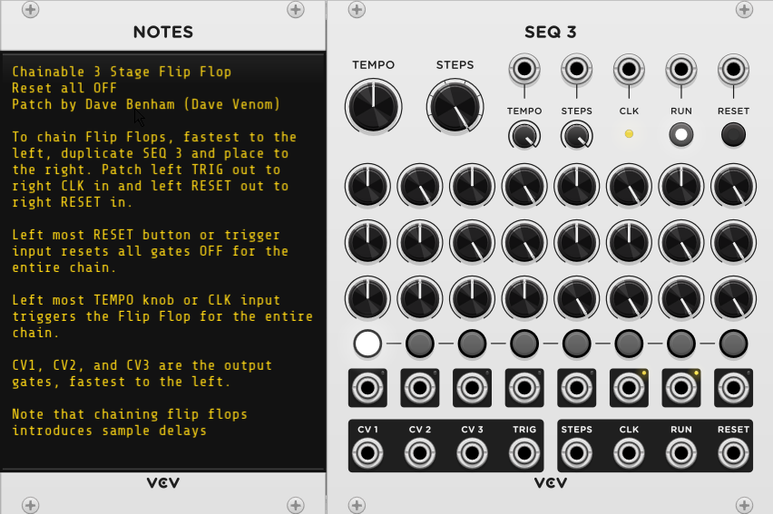
- Chainable 3 Stage Flip Flop - Resets OFF
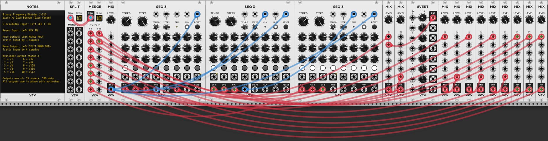
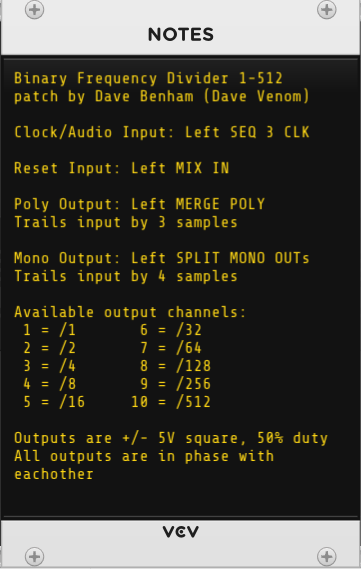
- Binary Frequency Divider 1-512
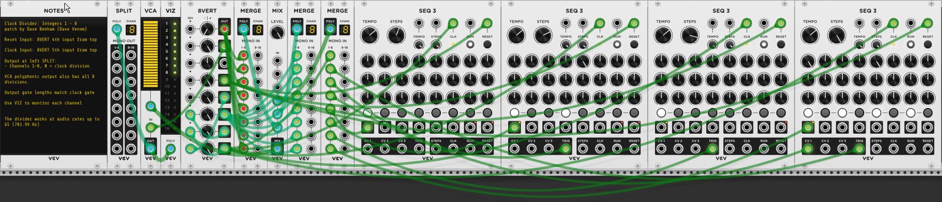
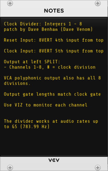
- Clock Divider - Integers 1-8
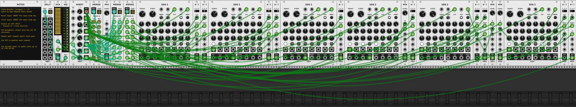
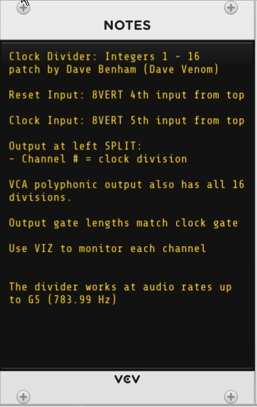
- Clock Divider - Integers 1-16
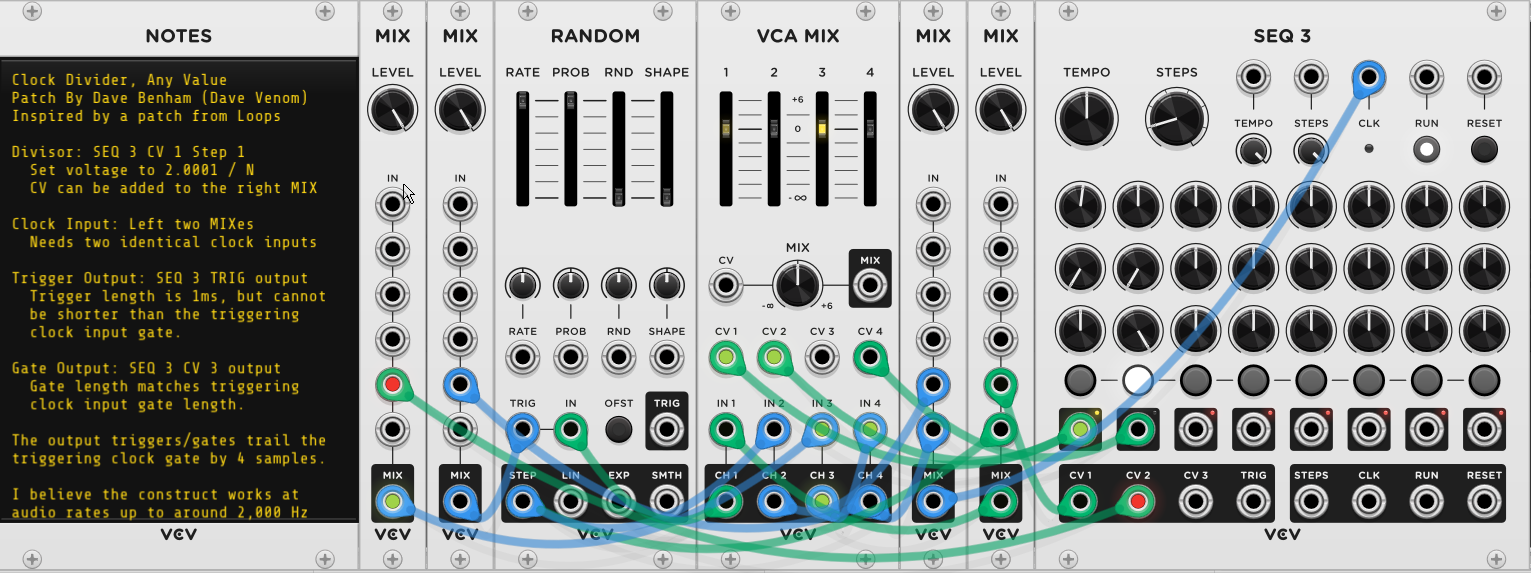
- Clock Divider - Any divisor N
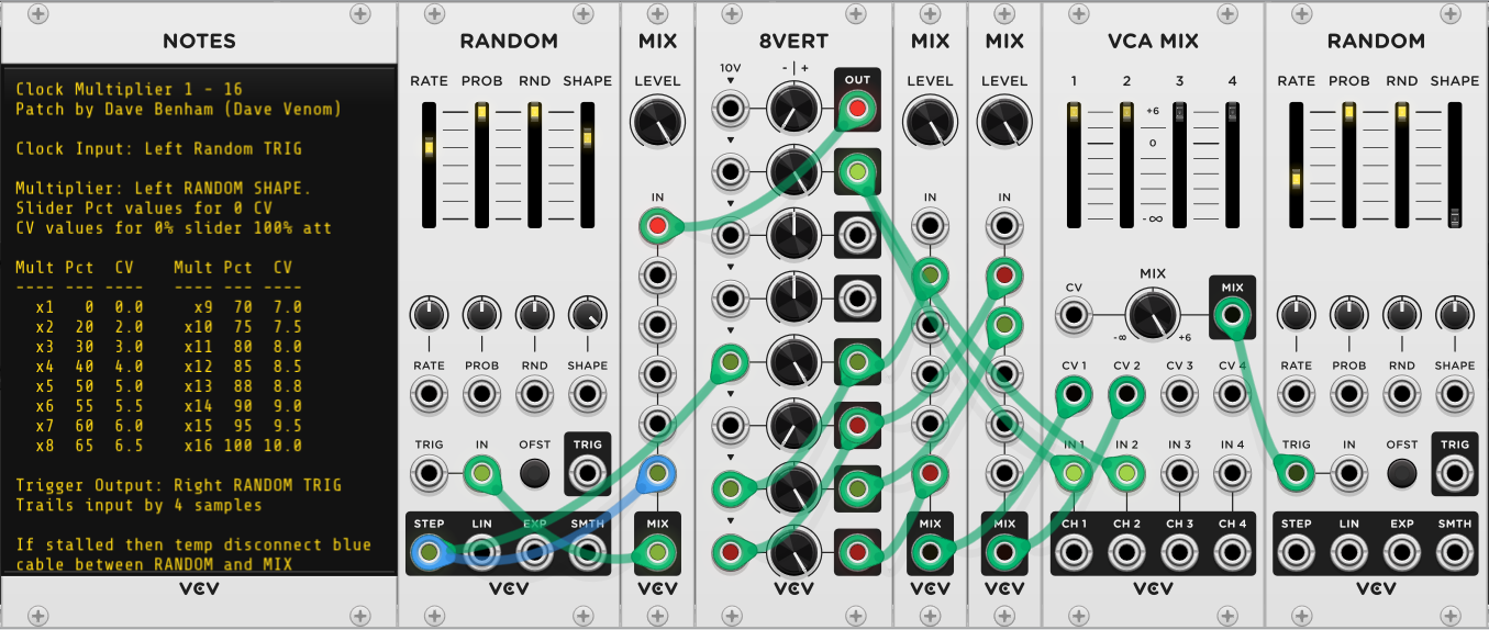
- Clock Multiplier 1-16
Gates / Triggers
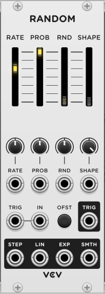
- Gate to Trigger - All you need is a RANDOM module!
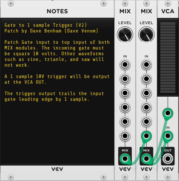
- Polyphonic Gate to 1 Sample Trigger
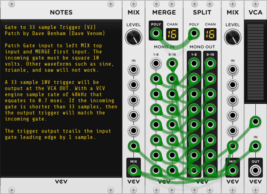
- Gate to 33 Sample Trigger
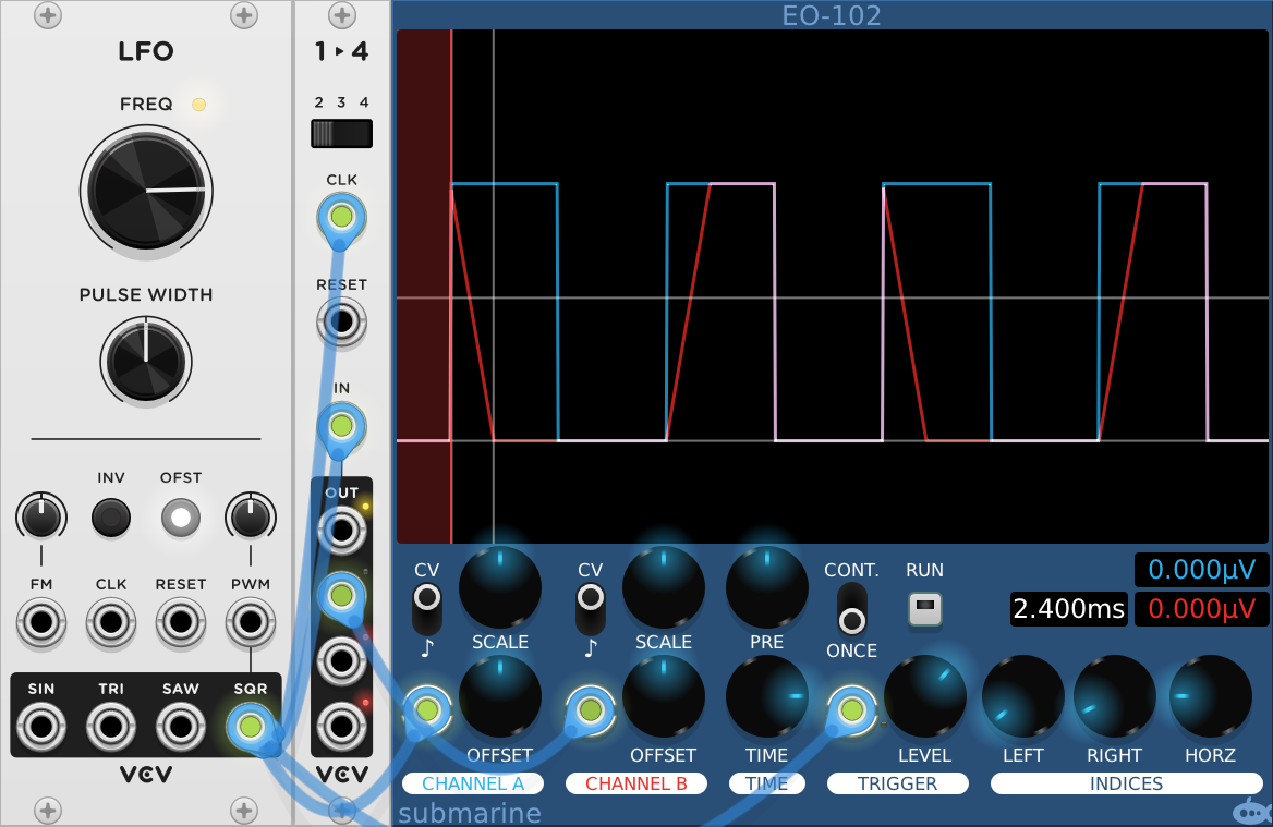
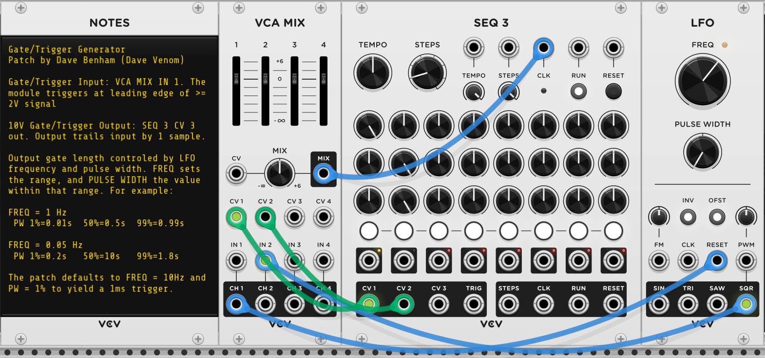
- Trigger / Gate Generator - Generates a precisely timed gate or trigger upon the leading edge of an input gate or trigger.
Envelope Generators
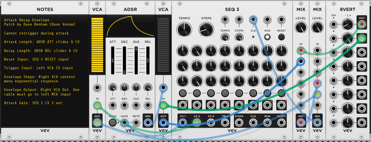
- AD Envelope - No retrigger during attack
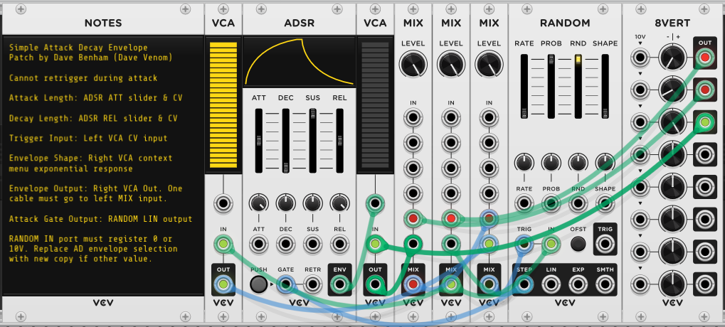
- Simple AD Envelope without Reset - No retrigger during attack
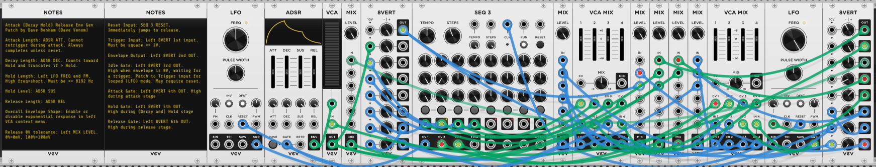
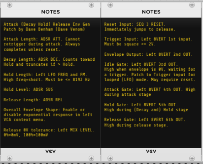
- A(DH)R Envelope - Attack (Timed Decay and Hold) Release. No retrigger during attack.
Wave Manipulation
- Rectifier
- Polyphonic Rectifier
- Amplitude Modulation
- Polyphonic Amplitude Modulation
- Ring Modulation
- Polyphonic Ring Modulation
- Hybrid Amplitude / Ring Modulation
- Polyphonic Hybrid Amplitude / Ring Modulation
Timing
- Simple CV Fade In/Out - Small and effective, but timings are inaccurate (but consistent)
- Precise CV Fade In/Out - Much larger, but very accurate timings.
- Countdown Timer
- Visual Countdown Timer
- Compact Countdown Timer Much smaller than the original
- Compact Visual Countdown Timer
Random Events / CV
- Simple Bernoulli Gate Specifies probability of selecting channel 2 (no toggle mode)
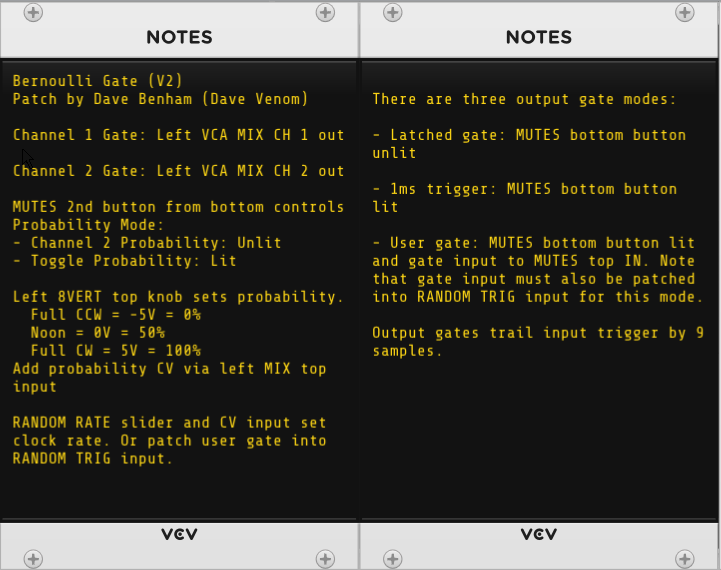
- Bernoulli Gate Specifies probability of selecting channel 2, or toggling between channel 1 and 2
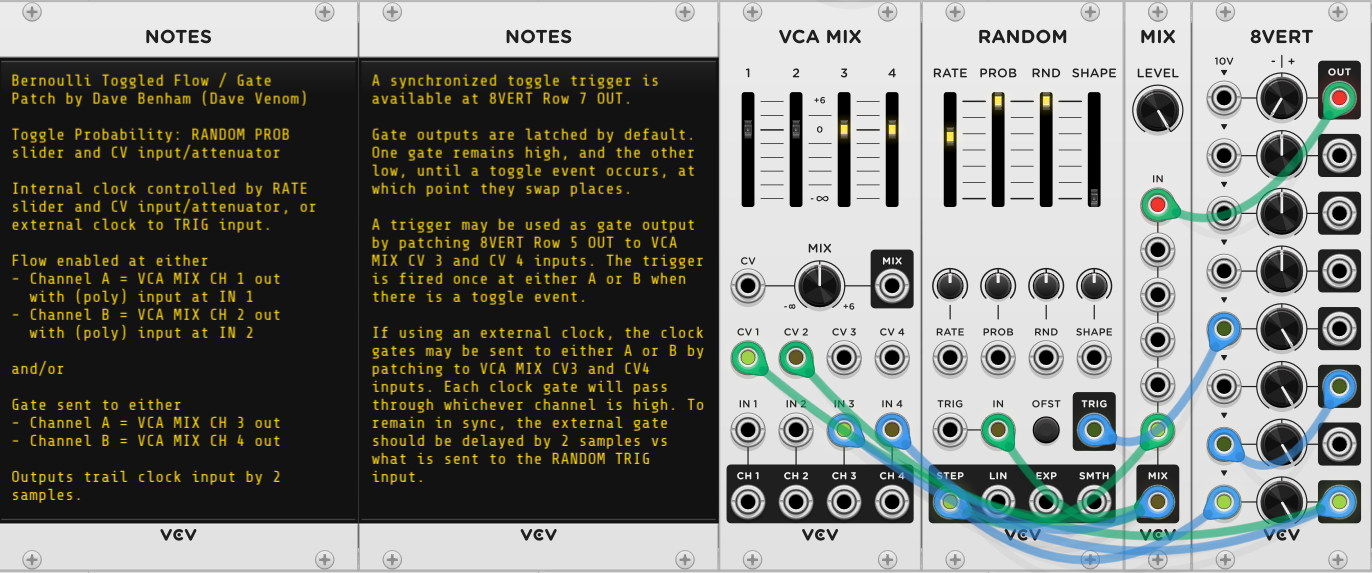
- Bernoulli Toggled Flow / Gate Specifies probability of toggling between channel 1 and 2, with direct support for controlling flow through channel 1 or 2.
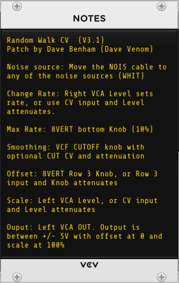
- Random Walk CV
Switches
- Polyphonic Sequential Switch 1 → 8 or 8 → 1
- CV Addressable Channel Selector - A handy utility that can drive multiple switches at the same time
- Switch N → 1 Direct 1 of N inputs to one output when paired with Channel Selector
- Switch 1 → N Direct 1 input to one of N outputs when paired with Channel Selector
Sequencers
Miscellaneous
- V/Oct Morphing LFO
- Digital Voltmeter - just for fun