VCV Fundamental Constructs

Math - Constant values, Scale values, and Multiply two inputs

Constant Big Integer CV

Easily generate a precise integral constant voltage with a range of +/- 1,000,000

VCV Fundamental Constant Big Integer CV.vcvs (4.9 KB)

7 x Constant CV +/- 100 or Scale 10

  • Generate up to 7 constant CV values with a range of +/- 100

or

  • Multiply input (polyphony supported) by up to 7 different scale factors with range of +/- 10

This is especially convenient for Constant CV as the knob percent number equals the output voltage.

VCV Fundamental 7 x Constant CV 100 - Scale 10.vcvs (2.9 KB)

7 x Constant CV +/- 1000 or Scale 100

  • Generate up to 7 constant CV values with a range of +/- 1000

or

  • Multiply input (polyphony supported) by up to 7 different scale factors with range of +/- 100

This is especially convenient for Scaling input CV as the knob percent number equals the scale factor.

VCV Fundamental 7 x Constant CV 1000 - Scale 100.vcvs (4.1 KB)

Polyphonic Scale +/- 10

Scale any input (polyphony supported) by a constant factor ranging from -10 to 10, with option to add offset CV input before scaling. This is a simple and compact construct.

VCV Fundamental Polyphonic Scale 10.vcvs (2.4 KB)

Polyphonic Scale +/- 100

Scale any input (polyphony supported) by a constant factor ranging from -100 to 100, with option to add offset CV input before scaling. This is nearly twice the size as the Scale 10, and the large scale factors are rarely needed, but it is very convenient to use because the knob percent number reads directly as the scale factor (100% = 100 x input)

VCV Fundamental Polyphonic Scale 100.vcvs (3.7 KB)

Multiply A x B

Multiply A (clipped at +/- 20V) times B (unconstrained)

VCV Fundamental Multiply.vcvs (14.1 KB)

1 Like

For the noobs here, what’s a Bernoulli Gate?

Randomly send gates or triggers to one of two channels.

Math - Comparators

All of these constructs compare incoming voltage against either constant CV, or else against another voltage source, and output either high (10V) or low (0V) depending on the relationship between the two.

One possible use for these is to convert analog signals into binary values (0 = False, 10 = True) so that logical operations (NOT, AND, OR) can be performed elsewhere (logic constructs still to come).

All the comparators use the same basic technique. A MIX sums together A + inverse B + 5 V. If A is >= B, then the result will be >= 5V. If A < B the result will be < 5V. That result is then used as CV for a VCA to attenuate a 1V input. The result will be >= 0.5 only if A >= B. That then passes through OCT to round the value to either 1 if A>=B, or 0 if A<B. Finally the result is amplified by a factor of 10 by VCA MIX to get the final output of 0V or 10V.

Many of my constructs elsewhere in this topic rely on some variation of this technique.

Comparator

Outputs 10V if A >= B. B can be constant CV, or another input signal.

VCV Fundamental Comparator 16.vcvs (16.8 KB)

Polyphonic Comparator

Outputs 10V if A >= B, with support for polyphonic inputs for both A and B.

VCV Fundamental Polyphonic Comparator.vcvs (12.3 KB)

Comparator x 16

16 Comparators that output 10V if A >= B. There are 16 inputs for A, and B is either a universal constant CV, or a monophonic input that is replicated for each of the comparators.

Window Comparator

Four outputs available that compare A against B, with a Window range to test if A equals B. Both B and the Window can be constant CV, or an input signal.

  • 10V if A >= B
  • 10V if A<B
  • 10V if A=B within a Window tolerance (|A-B| <= Window)
  • 10V if A <> B within a Window tolerance (|A-B| > Window)

VCV Fundamental Window Comparator.vcvs (15.9 KB)

Polyphonic Window Comparator

A polyphonic version of the Window Comparator. Both A and B are polyphonic inputs. The Window is either universal constant CV, or else a monophonic input that is replicated for each of the comparators.

The output is polyphonic.

VCV Fundamental Polyphonic Window Comparator.vcvs (29.8 KB)

Schmitt Trigger Comparator

A comparator with memory and two thresholds that is resistant to noise on the inputs. See the documentation in the Notes for a full description.

VCV Fundamental Schmitt Trigger.vcvs (11.9 KB)

4 Likes

MATH - Min / Max

Send two inputs in, and one output has the maximum voltage at that instant, and the other output the minimum.

A comparator creates two binary signals, one is 10V if A>=B, and the other is 10V if A<B. Then four VCAs are used as switches with the results of the comparison as the CV. The switches direct the signals to the correct outputs. Each input is sent to both outputs, but the VCAs only allow the correct values through.

Min / Max

Support for monophonic inputs A and B

VCV Fundamental Min Max.vcvs (12.5 KB)

Polyphonic Min / Max

A polyphonic version of the above.

VCV Fundamental Polyphonic Min Max.vcvs (23.3 KB)

3 Likes

LOGIC

All of the following logic constructs assume all inputs are binary with a voltage value of 0V (False) or 10V (True). If you have unconstrained analog inputs, you can use any of the Comparator constructs to convert them to binary before feeding them into a logic gate.

All of the logic constructs support polyphony. If all inputs are polyphonic, then the outputs will be polyphonic as well.

Most of the constructs include their own copy of an 8VERT to supply constant CV. But that can become wasteful if there are many logic gates in your patch. Feel free to patch in the needed constant CV from elsewhere and remove the redundant 8VERTs if you can.

Polyphonic NOT Gate

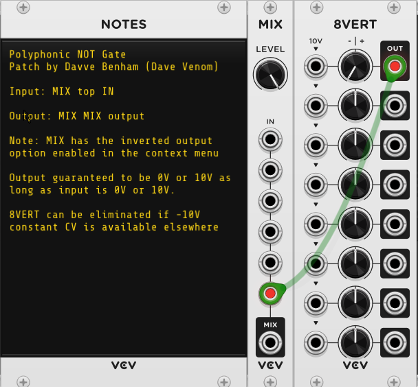
VCV Fundamental Polyphonic NOT Gate.vcvs (2.0 KB)

Polyphonic Simple OR Gate

It is “common knowledge” that a mixer can be used as a simple OR gate. However, the outputs are not restricted to 0V or 10V. This construct is included for completeness.

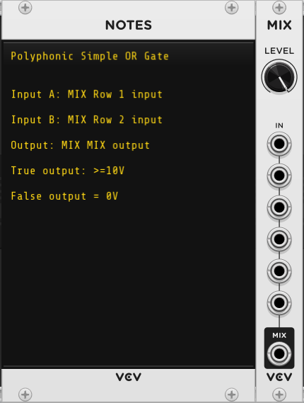
VCV Fundamental Polyphonic Simple OR Gate.vcvs (873 Bytes)

Polyphonic OR Gate

This slightly more complex version of an OR gate forces the output to be 0V or 10V.

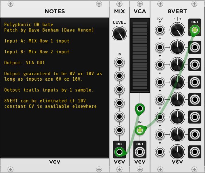
VCV Fundamental Polyphonic OR Gate.vcvs (2.6 KB)

Polyphonic Simple NOR Gate

Like most of the logic constructs, the negated version simply appends NOT logic to the base construct. The simple NOR may have false outputs that are < 0V.

VCV Fundamental Polyphonic Simple NOR Gate.vcvs (2.0 KB)

Polyphonic NOR Gate

Again, a bit more sophisticated version to force outputs to be 0V or 10V.

VCV Fundamental Polyphonic NOR Gate.vcvs (2.9 KB)

Polyphonic AND Gate

Another “common knowledge” construct that is included for completeness.

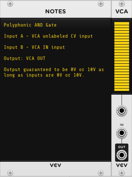
VCV Fundamental Polyphonic AND Gate.vcvs (876 Bytes)

Polyphonic NAND Gate

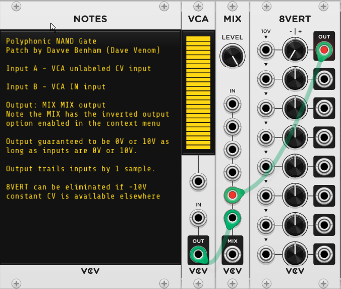
VCV Fundamental Polyphonic NAND Gate.vcvs (2.7 KB)

Polyphonic XOR Gate

An XOR gate can be created by combining OR AND NAND

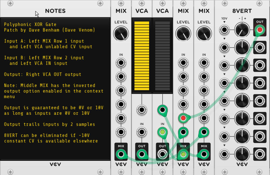
VCV Fundamental Polyphonic XOR Gate.vcvs (4.6 KB)

Polyphonic XNOR Gate

XNOR can be created by combining NOR OR AND

VCV Fundamental Polyphonic XNOR Gate.vcvs (4.8 KB)

Trivial Logic Demo

The following patch demonstrates each of the logic gates. There are two versions of the demo.

  • The version at the top includes the 8VERT for each logic gate.
  • The version at the bottom shows how it might look if the gates share a common 8VERT.

For each version, the top two MUTES buttons represent the A and B inputs, with lit representing FALSE, and unlit TRUE. The ML Voltmeter next to each gate shows the current value for A and B at the top, as well as the resultant output at the bottom.

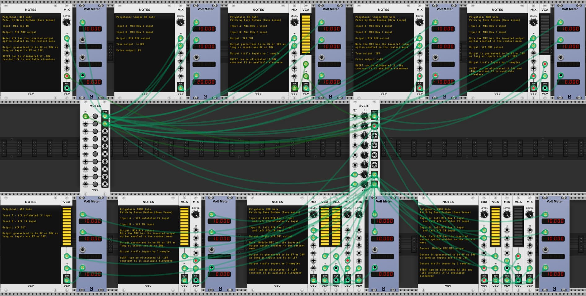
VCV Fundamental Logic.vcv (5.7 KB)

4 Likes

Clock Modulators / Frequency Dividers

Chainable 3 Stage Flip Flop - Resets ON

A SEQ 3 module with the correct settings works perfectly as a Flip Flop. And they can be chained by sending the Reset and Clock output triggers from one into the input of the next. This version sets all gates ON upon reset.

Note that each chained SEQ 3 flip flop runs one sample behind its parent unless you patch appropriate sample delays to the parent gate outputs.

VCV Fundamental Chainable 3 Stage Flip Flop - Resets ON.vcvs (3.8 KB)

Chainable 3 Stage Flip Flop - Resets OFF

This is identical to the previous construct, except all gates are set to OFF upon reset.

VCV Fundamental Chainable 3 Stage Flip Flop - Resets OFF.vcvs (3.8 KB)

Binary Frequency Divider 1-512

This construct chains 3 SEQ 3 flip flops together, but also adds carefully constructed sample delays to ensure that all gate outputs are in sync with each other. It provides power of two divisions from 1 to 512.

VCV Fundamental Binary Frequency Divider 1 - 512.vcvs (21.8 KB)

Clock Divider - Integers 1 - 8

This uses SEQ 3 modules and sample delays to provide integral clock divisions from 1 - 8.

VCV Fundamental Clock Divider Ints 1-8.vcvs (24.2 KB)

Clock Divider - Integers 1 - 16

4->1 Switches are added to extend the concept to integers beyond 8.

VCV Fundamental Clock Divider Ints 1-16.vcvs (47.8 KB)

Clock Divider - Any N

This patch is inspired by an idea/patch from Loops. It provides a reliable way to set a clock divisor of any value by simply entering a formula for a knob parameter: 2.0001 / N, where N is the desired divisor.

VCV Fundamental Clock Divider Any N.vcvs (10.3 KB)

I simplified Loops’ original idea by using a single SEQ 3 to take the place of a RANDOM and SEQ 3 pair.

The SEQ 3 uses 2 stages:

  • Stage 1 - Waiting for the Nth clock input
  • Stage 2 - Waiting for the triggering Nth clock input to go low

The RANDOM trigger has two clock inputs, each enabled/disabled by a VCA

  • The clock input which is only active during SEQ 3 stage 1
  • The end of stage 2 trigger which is only active during SEQ 3 stage 2

The SEQ 3 clock receives two inputs, also controlled by VCAs

  • The RANDOM STEP output, only active during stage 1
  • The negated clock input, only active during stage 2

The sum of the current RANDOM output + the delta passes through another VCA that is only active during stage 1.

The RANDOM starts out with an output of 0V. Each successive clock trigger adds the delta (2.0001/N), until a value >=2V is reached, which triggers the SEQ 3 to go to the second stage.

As long as the triggering clock remains high, the negated signal is low, so the 2nd stage remains active. Once the clock goes low, the negated signal goes high, which triggers the SEQ 3 to return to stage 1. It also triggers the RANDOM, but the 3rd VCA is off, so the IN receives 0V and the RANDOM is reset back to 0V - ready to start a new cycle.

I avoided the need of an 8VERT by using the various outputs available from the SEQ 3.

The stage gates provide the signals that control the VCAs.

The CV1 step 1 sets the delta (the divisor)

Both steps for CV2 are permanently set to -10V, which is needed to negate the incoming clock.

CV3 is permanently set to 10V at stage 2 to be used for the gate output. I could have used the 2nd stage gate as the gate output. But I opted to use CV3 to keep user patch points separate from the construct patch cables.

The SEQ 3 also conveniently provides the trigger for stage 2 as well.

Clock Multiplier 1-16

It wasn’t long ago I thought there would be no practical way to create a clock multiplier. But then I realized the RANDOM STEP output already has the ability to subdivide any given time unit by integral values from 1 to 16 via the SHAPE. All that is needed is a comparator that can detect each time the output voltage jumps to the next step (could be a positive or negative jump)

An inverted MIX module with a -10V constant CV plus the STEP output feeds the RANDOM input, so it toggles between 0V and 10V. The minimum step size (at 16 steps) is 0.625V. Multiply that value by 4 and you have more than enough to trigger another RANDOM, which also outputs a clean 1ms 10V trigger of it’s own.

To detect each jump, I use a MIX to sum the current STEP output with the inverted value of the previous sample that has been delayed 1 sample. I do the same with the inverted current value and the original previous sample. One of those sums will be positive going from 0 to 10, and the other when going down from 10 to 0. Both are used as CV for a VCA, with 10V input. Only the positive jump will register. The VCA MIX multiples by 4, which is enough to trigger the 2nd RANDOM.

Note that the clock divider may stall if the incoming clock rate changes too quickly. If that happens, simply momentarily disconnect the blue cable from the RANDOM STEP output to the MIX input.

One important thing that I did not discuss in the documentation - You can opt to randomly drop beats by setting the PROB slider below 100% on the right RANDOM module. This works really well with percussive voices to introduce life to the rhythm.

VCV Fundamental Clock Multiplier 1-16.vcvs (8.5 KB)

3 Likes

Wave Manipulation

Polyphonic Rectifier

A VCA functions as a half wave rectifier if you feed the signal into the CV input and 10V constant CV into the input. That will block the negative signal, leaving just the positive signal.

Invert the signal before rectifying, and you have the inverted negative signal. Invert again and you have the original negative signal.

A mixer can sum together the positive signal and the inverted negative signal to get full rectification.

It is quite simple with additional inverters to get all possible outputs. The only trick is to make sure each signal path goes through the same number of patch cables so they all stay in sync.

The Version 2 VCV VCA has great support for polyphony, and there is no need to replicate the constant 10V to multiple channels when rectifying a polyphonic signal.

VCV Fundamental Polyphonic Rectifier.vcvs (5.6 KB)

Amplitude Modulation

If your modulator is already unipolar, then all you need is a VCA. This construct includes convenient offset capability so it can work with bipolar modulators.

VCV Fundamental Amplitude Modulation.vcvs (3.3 KB)

Polyphonic Amplitude Modulation

This version simply adds a MERGE so the offset can be replicated to mix in with the polyphonic modulator.

If either the carrier or modulator is monophonic, then it need not be replicated - the VCA will automatically replicate the signal to match the channel count of the other. But if both inputs are polyphonic, then they should have the same number of channels.

Note that the cable that feeds the MERGE module must be replicated to match the number of channels in the modulator. For example, if the Modulator has three channels, then the MERGE should have the first three inputs fed by the top 8VERT OUT.

VCV Fundamental Polyphonic Amplitude Modulation.vcvs (4.0 KB)

Ring Modulation

Ring modulation requires multiplication of negative values. But the VCA CV input blocks negative values. So the carrier wave must be rectified with the positive signal going to one VCA, and the negative signal inverted before feeding into the 2nd VCA. The negative result must than be inverted again and then summed with the positive result. Management of sample delays is critical to make sure the summed signals align properly.

VCV Fundamental Ring Modulation.vcvs (5.4 KB)

Polyphonic Ring Modulation

Just need to swap in four VCA modules to replace the VCA MIX to get flexible polyphonic support.

As with the polyphonic amplitude modulation, if either the carrier or modulator is monophonic, then it need not be replicated - the VCAs will automatically replicate the signal to match the channel count of the other. But if both inputs are polyphonic, then they should have the same number of channels.

VCV Fundamental Polyphonic Ring Modulation.vcvs (6.5 KB)

Hybrid Amplitude / Ring Modulation

This combines features of the amplitude modulation and ring modulation.

If the modulator is bipolar, then offset by 5V and you have amplitude modulation. Use 0V offset to get ring modulation. Values in between give hybrid results. I don’t know what to call it if you use negative offset.

Polyphonic Hybrid Amplitude / Ring Modulation

A polyphonic version of the above.

As with the amplitude modulation, the MERGE module must have the cable feeding it replicated to match the number of channels in the modulator.

VCV Fundamental Polyphonic Hybrid AM - RM.vcvs (8.8 KB)

3 Likes

Timing

Simple CV Fade In/Out

This is simply an ADSR with a latching button to establish a long term gate to turn the CV on or off (with optional gate input), and a VCA to provide exponential response for more option on the shape of the fade in and out.

This is very effective and simple to build, but the ADSR attack and release timings are very inaccurate (but consistent)

VCV Fundamental Simple CV Fade In-Out.vcvs (5.9 KB)

Precise CV Fade In/Out

This uses a completely different design to achieve precise timing of the fade in and out times.

The SEQ 3 is used to keep track of what stage we are in, and establishes controlling voltages and gates for the different stages. The fade in/out shape and length are established by an LFO that gets reset at the beginning of each fade stage, so the shape and timings are consistent. The LFO signal also determines when the fade stage ends - it is scaled so that when the peak is reached, it is just enough to trigger the next SEQ 3 stage. VCAs are used as switches to control the flow of various voltages so they go to the correct destination depending on the stage.

VCV Fundamental Precise CV Fade In - Out.vcvs (12.5 KB)

Countdown Timer

This construct requires two different modules to serve as memory. The SEQ 3 keeps track of what stage the countdown is in (Waiting to start, Counting Down, or Countdown Complete), as well as establish controlling voltages and gates. A RANDOM is used to keep track of how many counts are left. At the input, each 0.0001 volt represents one count. That value is scaled up to 1V per count, and then Reset stores the initial count in the RANDOM. Upon countdown start, each clock tick stores the current value minus 1V. The countdown is complete once 0V is reached.

VCV Fundamental Countdown Timer.vcvs (17.2 KB)

Visual Countdown Timer

Same as above, but additional modules are used to compute the digits of the various powers of ten in the count number across polyphonic channels so they can be graphically displayed by a VCA. This can be handy as a performance aid to keep track of how much time is left.

VCV Fundamental Visual Countdown Timer.vcvs (25.5 KB)

Compact Countdown Timer

After building the Clock Divider Any N, I realized I could build a much smaller countdown timer as long as I don’t care about generating an integral voltage that represents the count remaining. As with the clock divider, simply increment RANDOM by 2.0001 / N, and the controlling switch will end the count once 2V is achieved.

VCV Fundamental Compact Countdown Timer.vcvs (8.9 KB)

Compact Visual Countdown Timer

I add a visual display of the remaining counts by multiplying the current RANDOM voltage by 5, inverting, and then summing with 10V. The result is graphically displayed by the VCA Level.

VCV Fundamental Compact Visual Countdown Timer.vcvs (11.9 KB)

2 Likes

Switches

The VCV 1->4 and 4->1 switches have a slew limiter that makes them great for audio, but not so good for switching CV. Here are constructs without any slew limiting that work well with CV.

Polyphonic Sequential Switch 1->8 or 8->1

The SEQ 3 does most of the work, and doesn’t even need configuring, other than to specify the number of steps. The VCAs use the SEQ 3 gates to control which channel is active.

VCV Fundamental Polyphonic Switch 8-1 or 1-8.vcvs (8.1 KB)

CV Addressable Channel Selector

Generates a polyphonic output with the selected channel having a 10V gate, and the others 0V. Unipolar CV is used to select a channel.

This construct was originally intended to be used with any number of N->1 or 1->N switches. But the output could be used any way you see fit.

Unlike the sequential switches, the channels can be selected in any order with appropriate CV input.

  • LFO saw wave for ascending order
  • Inverted LFO saw wave for descending order
  • Triangle wave for ping pong
  • RANDOM sample and hold for random order
  • SEQ 3 sequence for user assignable pattern

Use the Channel Selector to drive as many switches as you want!

VCV Fundamental CV Addressable Channel Selector.vcvs (25.5 KB)

Switch N → 1

A simple patch to be used with the Channel Selector that allows directing one of N inputs to a single output.

VCV Fundamental Switch N to 1.vcvs (2.2 KB)

Switch 1 → N

Another simple patch to be used with the Channel Selector to send 1 input to any one of N outputs.

VCV Fundamental Switch 1 to N.vcvs (1.6 KB)

3 Likes

I have replace the Random Walk CV with version 3 that is significantly smaller and more CPU efficient. But it is functionally the same. I also attempted to explain how it works.

1 Like

you are on a roll with these, very educational, thanks!

2 Likes

Miscellaneous

Morphing V/Oct LFO

The RANDOM module can easily be made to oscillate by patching 5V to the input, then slowing the RATE down to the minimum, removing the IN input, and then taking the STEP output to a MIX with invert enabled and patching that to the RANDOM IN input. Then turn the RATE back up.

Then STEP, LIN, EXP, and SMTH outputs will all produce nice well behaved oscillations. With SHAPE at 0, they are all square. The fun starts as the SHAPE is increased, and each waveform morphs into a different shape. Perhaps the most interesting is the stepped triangle that can be gotten from the STEP output.

Without any Rate CV, the frequency will be 1/2 the clock rate shown by RANDOM. The CV is scaled to be V/Oct when the attenuation is 100%.

The only problem is the initial output is always 0 upon patch load. So the oscillations need to be jump started with the 5V signal every time. The solution is to use a NOT gate instead of inversion, so it oscillates between 0 and 10V, and the 0 startup voltage works just fine.

There is still a potential issue, the oscillator may stall when getting into mid range audio rates while the SHAPE is non zero. So a mechanism needs to be in place to temporarily restore the IN voltage to 0V. MUTES works well for this.

I hope to produce a video about this oscillator, but in the mean time, hear is the construct for a morphing LFO that allows blending of the different waveforms. A mixture of positive and negative percents can yield particularly interesting shapes. Use the built in offset and attenuation to keep the output in the desired range.

VCV Fundamental Morphing LFO.vcvs (10.2 KB)

Digital Voltmeter

This is not really practical - the construct is quite large and CPU intensive. But it was a fun challenge to produce a construct that could display the voltage of a signal using only VCV Fundamental modules. It supports any voltage between -17 and 17 exclusive.

VCV Fundamental Digital Voltmeter.vcvs (71.7 KB)

1 Like

Here is an instructive little demo patch that utilizes the following constructs:

  • Morphing V/Oct LFO
  • CV Addressable Channel Selector
  • Switch N → 1

It shows the VCV LFO can be used to drive a 4->1 switch in ascending mode (Saw wave), descending mode (Inverted Saw wave, otherwise known as a Ramp wave), and in ping pong mode with a triangle wave.

The problem with the ping pong is the note lengths are not constant because the top and bottom notes play twice - once while ascending, and again while descending. So the top and bottom notes are twice as long as the inner two notes.

The problem is nicely solved by using a stepped triangle from the Morphing V/Oct LFO.

LFO and Switch Demo.vcv (6.0 KB)

1 Like

Here’s my contribution to this pleasant thread. Had a quick peek at the above patches and I don’t think I’ll be duplicating any of them, even though some are quite similar.

This is a clock divider of sorts, but which will accept any multiple.

The triggers or gates don’t have to come from a steady clock signal; they can be out-of-sync / random and it will still work. So basically, at every nth trigger/gate, it will let that signal through. To test the patch, I used the PULSES module, but you can easily replace this with any clock, LFO, midi input, etc.

To accomplish this, I started with the RANDOM module. Knowing that it takes at least a 2V signal to trigger it, I just had to complete the expression 2 / n (where n being the number of beats… ex : if n = 5, the trigger/gate will go through at every fifth beat)

Now that simple expressions can be entered when right-clicking on a knob, I apply this logic to the first knob of the 8VERT module (circled in orange in the above graphic) :

image

Then with another RANDOM module (plus a MIX module), I can store these increments with some S&H. So with the 2 / 5 example, the following values will be held :

  • 0 + (2 / 5) = 0.4V
  • 0.4 + (2 / 5) = 0.8V
  • 0.8 + (2 / 5) = 1.2V
  • 1.2 + (2 / 5) = 1.6V
  • 1.6 + (2 / 5) = 2.0V

Once the 2.0V value is obtained, there’s a bit of resetting going so that the cycle can repeat.

If you want the original trigger/gate to be perfectly aligned (at the exact same sample) with the one that goes through the divider, use the last 8VERT output (circled in pink in the above graphic) and the CV2 output of the SEQ3 module (circled in yellow in the above graphic).

Works just as well with triggers…

image

…as with gates

image

Something I haven’t explored yet with this patch is modulating the first CV input in 8VERT. Could yield interesting results :slight_smile:

clock divider (any multiple).vcv (1.5 KB)

4 Likes

Nice idea to use the RANDOM to count the clock ticks. I had used RAMDOM for my countdown timer, but hadn’t thought to use that technique for a clock divider.

Thank you for pointing out the technique of entering a mathematical formula with a knob right click. I had seen that when V2 was first released, but then totally forgot about it. That can be really handy - I just need to remember to use it!

The night before you posted this I realized that the RANDOM trigger is effectively a comparator with a fixed threshold of 2V. I actually built a Bernoulli Gate (Trigger actually) using two RANDOMs that is significantly smaller than my existing Bernoulli gate patches, but I haven’t pulled the trigger on posting it.

You shouldn’t need the SEQ 3 to perform the reset. The 2nd RANDOM output can toggle between high and low easy enough, and that is enough to derive the logic to reset the construct after the count is complete. I’ve got a working version, but I’m not sure it is the best option yet.

The other option is to ditch the 2nd RANDOM, and use SEQ 3 on its own instead. I believe it also triggers at 2V. It can provide up to 3 fixed voltages for each stage, and that can take the place of some other modules, making it easier to reset, thus perhaps making up for its large size.

I’ve got to get to bed, hopefully I can work on this tomorrow. Or perhaps you can beat me to it.

1 Like

If you or anybody else can simplify this one down, please feel free to do so. My construct still feels more convoluted than it ought to be and I might have overlooked the straightforward approach (I’m great at making a mountain out of a molehill when patching!).

My findings while building this one :

  • I needed to add a slight positive offset (0.0001V in this case) to the increments, otherwise some of the divisions would require an extra beat to let the trigger/gate through. Take 2 / 6 for example : adding 0.33333V six times will result in 1.99998V. For some reason that evades me, even some of the clean divisions like 2 / 4 (0.5V) would not trigger on the fourth beat. But when adding the offset, every division I’ve verified so far was falling on the correct beat. In my patch, this offset is provided by the 8VERT’s 3rd output.

  • The trigger for the RANDOM module must be sent a value lower than 0.1V if you want to arm it for the next trigger (value of 2V or more). This threw a small wrench in my setup. :monkey: :wrench:

Really like the 2nd option you brought up about using the SEQ3 instead. I just gave it a quick try and yes, it does require 2V to trigger, just like RANDOM. On top of having those 3 fixed voltages, I like having the presence of the reset feature as well!

1 Like

I’ve added what I think is an elegant final solution based on your original idea of using RANDOM to count the clock ticks. You can find it at the bottom of this post - VCV Fundamental Constructs - #21 by DaveVenom

You should see the early versions of some of my constructs!

Yes, I thought about that, and confirmed that can be a problem. Floating point arithmetic can be tricky. Comparisons typically require some type of tolerance factor. My solution is to use 2.0001/N instead of 2/N. Not as convenient to type, but I think it is very reliable. Simply adding .0001 to your delta (2/N + 0.0001) will eventually cause problems as N gets larger.

I’m not sure what you are saying here. Hopefully my construct does not suffer from this.

1 Like

:+1: Cool beans! I’ll try to check it out soon

True, I didn’t bother with very high values for the n variable so far. For curiosity’s sake, I’ll take the patch for a test drive to see how high I can go until I run into inaccuracies.

The trigger input of the 2nd RANDOM module is receiving the held increments from the 1st RANDOM module. So with the 2 / 5 example, only the values of 0.4, 0.8, 1.2, 1.6 and 2.0 run through that cable. It never dips below 0.4V, which isn’t low enough to re-arm the trigger input of the 2nd module.

So the first time the 2nd module encounters a 2.0V value or above (once the patch is opened in VCV), the trigger will function properly. But any subsequent encounter with a 2.0V+ value or above will only work if the voltage drops below 0.1V beforehand.

That’s why there are two VCA modules in my patch. They are used to interject a 0V value into the S&H so that the 2nd RANDOM module can properly reset.

After completing the “Clock Divider Any N”, I realized I could dramatically simplify my countdown timers. I posted new compact forms of the countdown timers