Timing
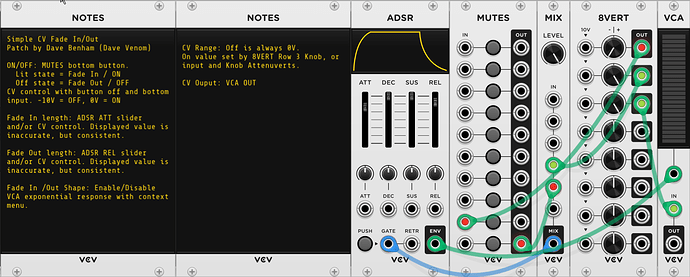
Simple CV Fade In/Out
This is simply an ADSR with a latching button to establish a long term gate to turn the CV on or off (with optional gate input), and a VCA to provide exponential response for more option on the shape of the fade in and out.
This is very effective and simple to build, but the ADSR attack and release timings are very inaccurate (but consistent)
VCV Fundamental Simple CV Fade In-Out.vcvs (5.9 KB)
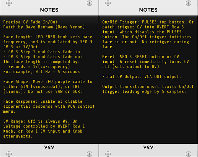
Precise CV Fade In/Out
This uses a completely different design to achieve precise timing of the fade in and out times.
The SEQ 3 is used to keep track of what stage we are in, and establishes controlling voltages and gates for the different stages. The fade in/out shape and length are established by an LFO that gets reset at the beginning of each fade stage, so the shape and timings are consistent. The LFO signal also determines when the fade stage ends - it is scaled so that when the peak is reached, it is just enough to trigger the next SEQ 3 stage. VCAs are used as switches to control the flow of various voltages so they go to the correct destination depending on the stage.
VCV Fundamental Precise CV Fade In - Out.vcvs (12.5 KB)
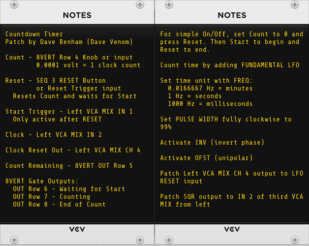
Countdown Timer
This construct requires two different modules to serve as memory. The SEQ 3 keeps track of what stage the countdown is in (Waiting to start, Counting Down, or Countdown Complete), as well as establish controlling voltages and gates. A RANDOM is used to keep track of how many counts are left. At the input, each 0.0001 volt represents one count. That value is scaled up to 1V per count, and then Reset stores the initial count in the RANDOM. Upon countdown start, each clock tick stores the current value minus 1V. The countdown is complete once 0V is reached.
VCV Fundamental Countdown Timer.vcvs (17.2 KB)
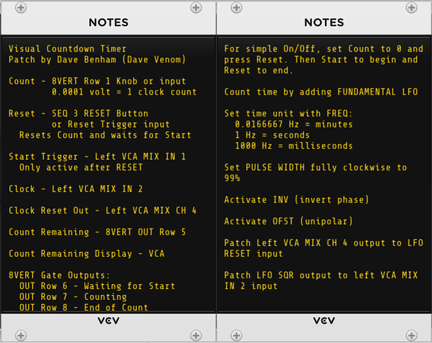
Visual Countdown Timer
Same as above, but additional modules are used to compute the digits of the various powers of ten in the count number across polyphonic channels so they can be graphically displayed by a VCA. This can be handy as a performance aid to keep track of how much time is left.
VCV Fundamental Visual Countdown Timer.vcvs (25.5 KB)
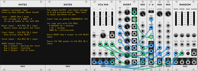
Compact Countdown Timer
After building the Clock Divider Any N, I realized I could build a much smaller countdown timer as long as I don’t care about generating an integral voltage that represents the count remaining. As with the clock divider, simply increment RANDOM by 2.0001 / N, and the controlling switch will end the count once 2V is achieved.
VCV Fundamental Compact Countdown Timer.vcvs (8.9 KB)
Compact Visual Countdown Timer
I add a visual display of the remaining counts by multiplying the current RANDOM voltage by 5, inverting, and then summing with 10V. The result is graphically displayed by the VCA Level.
VCV Fundamental Compact Visual Countdown Timer.vcvs (11.9 KB)
