Clock Modulators / Frequency Dividers
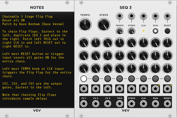
Chainable 3 Stage Flip Flop - Resets ON
A SEQ 3 module with the correct settings works perfectly as a Flip Flop. And they can be chained by sending the Reset and Clock output triggers from one into the input of the next. This version sets all gates ON upon reset.
Note that each chained SEQ 3 flip flop runs one sample behind its parent unless you patch appropriate sample delays to the parent gate outputs.
VCV Fundamental Chainable 3 Stage Flip Flop - Resets ON.vcvs (3.8 KB)
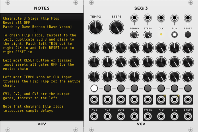
Chainable 3 Stage Flip Flop - Resets OFF
This is identical to the previous construct, except all gates are set to OFF upon reset.
VCV Fundamental Chainable 3 Stage Flip Flop - Resets OFF.vcvs (3.8 KB)
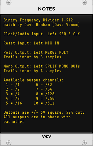
Binary Frequency Divider 1-512
This construct chains 3 SEQ 3 flip flops together, but also adds carefully constructed sample delays to ensure that all gate outputs are in sync with each other. It provides power of two divisions from 1 to 512.
VCV Fundamental Binary Frequency Divider 1 - 512.vcvs (21.8 KB)
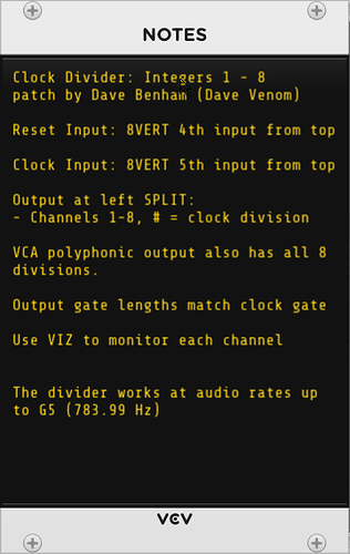
Clock Divider - Integers 1 - 8
This uses SEQ 3 modules and sample delays to provide integral clock divisions from 1 - 8.
VCV Fundamental Clock Divider Ints 1-8.vcvs (24.2 KB)
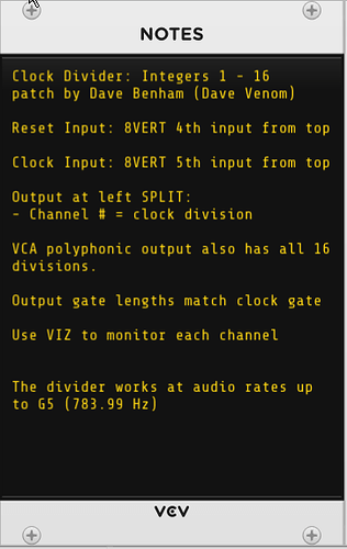
Clock Divider - Integers 1 - 16
4->1 Switches are added to extend the concept to integers beyond 8.
VCV Fundamental Clock Divider Ints 1-16.vcvs (47.8 KB)
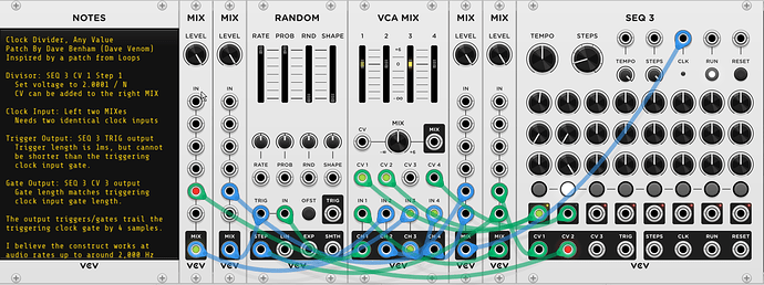
Clock Divider - Any N
This patch is inspired by an idea/patch from Loops. It provides a reliable way to set a clock divisor of any value by simply entering a formula for a knob parameter: 2.0001 / N, where N is the desired divisor.
VCV Fundamental Clock Divider Any N.vcvs (10.3 KB)
I simplified Loops’ original idea by using a single SEQ 3 to take the place of a RANDOM and SEQ 3 pair.
The SEQ 3 uses 2 stages:
- Stage 1 - Waiting for the Nth clock input
- Stage 2 - Waiting for the triggering Nth clock input to go low
The RANDOM trigger has two clock inputs, each enabled/disabled by a VCA
- The clock input which is only active during SEQ 3 stage 1
- The end of stage 2 trigger which is only active during SEQ 3 stage 2
The SEQ 3 clock receives two inputs, also controlled by VCAs
- The RANDOM STEP output, only active during stage 1
- The negated clock input, only active during stage 2
The sum of the current RANDOM output + the delta passes through another VCA that is only active during stage 1.
The RANDOM starts out with an output of 0V. Each successive clock trigger adds the delta (2.0001/N), until a value >=2V is reached, which triggers the SEQ 3 to go to the second stage.
As long as the triggering clock remains high, the negated signal is low, so the 2nd stage remains active. Once the clock goes low, the negated signal goes high, which triggers the SEQ 3 to return to stage 1. It also triggers the RANDOM, but the 3rd VCA is off, so the IN receives 0V and the RANDOM is reset back to 0V - ready to start a new cycle.
I avoided the need of an 8VERT by using the various outputs available from the SEQ 3.
The stage gates provide the signals that control the VCAs.
The CV1 step 1 sets the delta (the divisor)
Both steps for CV2 are permanently set to -10V, which is needed to negate the incoming clock.
CV3 is permanently set to 10V at stage 2 to be used for the gate output. I could have used the 2nd stage gate as the gate output. But I opted to use CV3 to keep user patch points separate from the construct patch cables.
The SEQ 3 also conveniently provides the trigger for stage 2 as well.
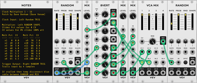
Clock Multiplier 1-16
It wasn’t long ago I thought there would be no practical way to create a clock multiplier. But then I realized the RANDOM STEP output already has the ability to subdivide any given time unit by integral values from 1 to 16 via the SHAPE. All that is needed is a comparator that can detect each time the output voltage jumps to the next step (could be a positive or negative jump)
An inverted MIX module with a -10V constant CV plus the STEP output feeds the RANDOM input, so it toggles between 0V and 10V. The minimum step size (at 16 steps) is 0.625V. Multiply that value by 4 and you have more than enough to trigger another RANDOM, which also outputs a clean 1ms 10V trigger of it’s own.
To detect each jump, I use a MIX to sum the current STEP output with the inverted value of the previous sample that has been delayed 1 sample. I do the same with the inverted current value and the original previous sample. One of those sums will be positive going from 0 to 10, and the other when going down from 10 to 0. Both are used as CV for a VCA, with 10V input. Only the positive jump will register. The VCA MIX multiples by 4, which is enough to trigger the 2nd RANDOM.
Note that the clock divider may stall if the incoming clock rate changes too quickly. If that happens, simply momentarily disconnect the blue cable from the RANDOM STEP output to the MIX input.
One important thing that I did not discuss in the documentation - You can opt to randomly drop beats by setting the PROB slider below 100% on the right RANDOM module. This works really well with percussive voices to introduce life to the rhythm.
