VCV Fundamental Constructs

Switches

The VCV 1->4 and 4->1 switches have a slew limiter that makes them great for audio, but not so good for switching CV. Here are constructs without any slew limiting that work well with CV.

Polyphonic Sequential Switch 1->8 or 8->1

The SEQ 3 does most of the work, and doesn’t even need configuring, other than to specify the number of steps. The VCAs use the SEQ 3 gates to control which channel is active.

VCV Fundamental Polyphonic Switch 8-1 or 1-8.vcvs (8.1 KB)

CV Addressable Channel Selector

Generates a polyphonic output with the selected channel having a 10V gate, and the others 0V. Unipolar CV is used to select a channel.

This construct was originally intended to be used with any number of N->1 or 1->N switches. But the output could be used any way you see fit.

Unlike the sequential switches, the channels can be selected in any order with appropriate CV input.

  • LFO saw wave for ascending order
  • Inverted LFO saw wave for descending order
  • Triangle wave for ping pong
  • RANDOM sample and hold for random order
  • SEQ 3 sequence for user assignable pattern

Use the Channel Selector to drive as many switches as you want!

VCV Fundamental CV Addressable Channel Selector.vcvs (25.5 KB)

Switch N → 1

A simple patch to be used with the Channel Selector that allows directing one of N inputs to a single output.

VCV Fundamental Switch N to 1.vcvs (2.2 KB)

Switch 1 → N

Another simple patch to be used with the Channel Selector to send 1 input to any one of N outputs.

VCV Fundamental Switch 1 to N.vcvs (1.6 KB)

3 Likes

I have replace the Random Walk CV with version 3 that is significantly smaller and more CPU efficient. But it is functionally the same. I also attempted to explain how it works.

1 Like

you are on a roll with these, very educational, thanks!

2 Likes

Miscellaneous

Morphing V/Oct LFO

The RANDOM module can easily be made to oscillate by patching 5V to the input, then slowing the RATE down to the minimum, removing the IN input, and then taking the STEP output to a MIX with invert enabled and patching that to the RANDOM IN input. Then turn the RATE back up.

Then STEP, LIN, EXP, and SMTH outputs will all produce nice well behaved oscillations. With SHAPE at 0, they are all square. The fun starts as the SHAPE is increased, and each waveform morphs into a different shape. Perhaps the most interesting is the stepped triangle that can be gotten from the STEP output.

Without any Rate CV, the frequency will be 1/2 the clock rate shown by RANDOM. The CV is scaled to be V/Oct when the attenuation is 100%.

The only problem is the initial output is always 0 upon patch load. So the oscillations need to be jump started with the 5V signal every time. The solution is to use a NOT gate instead of inversion, so it oscillates between 0 and 10V, and the 0 startup voltage works just fine.

There is still a potential issue, the oscillator may stall when getting into mid range audio rates while the SHAPE is non zero. So a mechanism needs to be in place to temporarily restore the IN voltage to 0V. MUTES works well for this.

I hope to produce a video about this oscillator, but in the mean time, hear is the construct for a morphing LFO that allows blending of the different waveforms. A mixture of positive and negative percents can yield particularly interesting shapes. Use the built in offset and attenuation to keep the output in the desired range.

VCV Fundamental Morphing LFO.vcvs (10.2 KB)

Digital Voltmeter

This is not really practical - the construct is quite large and CPU intensive. But it was a fun challenge to produce a construct that could display the voltage of a signal using only VCV Fundamental modules. It supports any voltage between -17 and 17 exclusive.

VCV Fundamental Digital Voltmeter.vcvs (71.7 KB)

1 Like

Here is an instructive little demo patch that utilizes the following constructs:

  • Morphing V/Oct LFO
  • CV Addressable Channel Selector
  • Switch N → 1

It shows the VCV LFO can be used to drive a 4->1 switch in ascending mode (Saw wave), descending mode (Inverted Saw wave, otherwise known as a Ramp wave), and in ping pong mode with a triangle wave.

The problem with the ping pong is the note lengths are not constant because the top and bottom notes play twice - once while ascending, and again while descending. So the top and bottom notes are twice as long as the inner two notes.

The problem is nicely solved by using a stepped triangle from the Morphing V/Oct LFO.

LFO and Switch Demo.vcv (6.0 KB)

1 Like

Here’s my contribution to this pleasant thread. Had a quick peek at the above patches and I don’t think I’ll be duplicating any of them, even though some are quite similar.

This is a clock divider of sorts, but which will accept any multiple.

The triggers or gates don’t have to come from a steady clock signal; they can be out-of-sync / random and it will still work. So basically, at every nth trigger/gate, it will let that signal through. To test the patch, I used the PULSES module, but you can easily replace this with any clock, LFO, midi input, etc.

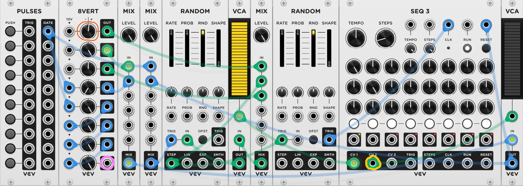
To accomplish this, I started with the RANDOM module. Knowing that it takes at least a 2V signal to trigger it, I just had to complete the expression 2 / n (where n being the number of beats… ex : if n = 5, the trigger/gate will go through at every fifth beat)

Now that simple expressions can be entered when right-clicking on a knob, I apply this logic to the first knob of the 8VERT module (circled in orange in the above graphic) :

image

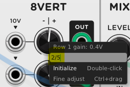
Then with another RANDOM module (plus a MIX module), I can store these increments with some S&H. So with the 2 / 5 example, the following values will be held :

  • 0 + (2 / 5) = 0.4V
  • 0.4 + (2 / 5) = 0.8V
  • 0.8 + (2 / 5) = 1.2V
  • 1.2 + (2 / 5) = 1.6V
  • 1.6 + (2 / 5) = 2.0V

Once the 2.0V value is obtained, there’s a bit of resetting going so that the cycle can repeat.

If you want the original trigger/gate to be perfectly aligned (at the exact same sample) with the one that goes through the divider, use the last 8VERT output (circled in pink in the above graphic) and the CV2 output of the SEQ3 module (circled in yellow in the above graphic).

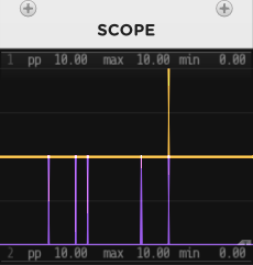
Works just as well with triggers…
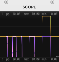
image

…as with gates

image

Something I haven’t explored yet with this patch is modulating the first CV input in 8VERT. Could yield interesting results :slight_smile:

clock divider (any multiple).vcv (1.5 KB)

4 Likes

Nice idea to use the RANDOM to count the clock ticks. I had used RAMDOM for my countdown timer, but hadn’t thought to use that technique for a clock divider.

Thank you for pointing out the technique of entering a mathematical formula with a knob right click. I had seen that when V2 was first released, but then totally forgot about it. That can be really handy - I just need to remember to use it!

The night before you posted this I realized that the RANDOM trigger is effectively a comparator with a fixed threshold of 2V. I actually built a Bernoulli Gate (Trigger actually) using two RANDOMs that is significantly smaller than my existing Bernoulli gate patches, but I haven’t pulled the trigger on posting it.

You shouldn’t need the SEQ 3 to perform the reset. The 2nd RANDOM output can toggle between high and low easy enough, and that is enough to derive the logic to reset the construct after the count is complete. I’ve got a working version, but I’m not sure it is the best option yet.

The other option is to ditch the 2nd RANDOM, and use SEQ 3 on its own instead. I believe it also triggers at 2V. It can provide up to 3 fixed voltages for each stage, and that can take the place of some other modules, making it easier to reset, thus perhaps making up for its large size.

I’ve got to get to bed, hopefully I can work on this tomorrow. Or perhaps you can beat me to it.

1 Like

If you or anybody else can simplify this one down, please feel free to do so. My construct still feels more convoluted than it ought to be and I might have overlooked the straightforward approach (I’m great at making a mountain out of a molehill when patching!).

My findings while building this one :

  • I needed to add a slight positive offset (0.0001V in this case) to the increments, otherwise some of the divisions would require an extra beat to let the trigger/gate through. Take 2 / 6 for example : adding 0.33333V six times will result in 1.99998V. For some reason that evades me, even some of the clean divisions like 2 / 4 (0.5V) would not trigger on the fourth beat. But when adding the offset, every division I’ve verified so far was falling on the correct beat. In my patch, this offset is provided by the 8VERT’s 3rd output.

  • The trigger for the RANDOM module must be sent a value lower than 0.1V if you want to arm it for the next trigger (value of 2V or more). This threw a small wrench in my setup. :monkey: :wrench:

Really like the 2nd option you brought up about using the SEQ3 instead. I just gave it a quick try and yes, it does require 2V to trigger, just like RANDOM. On top of having those 3 fixed voltages, I like having the presence of the reset feature as well!

1 Like

I’ve added what I think is an elegant final solution based on your original idea of using RANDOM to count the clock ticks. You can find it at the bottom of this post - VCV Fundamental Constructs - #21 by DaveVenom

You should see the early versions of some of my constructs!

Yes, I thought about that, and confirmed that can be a problem. Floating point arithmetic can be tricky. Comparisons typically require some type of tolerance factor. My solution is to use 2.0001/N instead of 2/N. Not as convenient to type, but I think it is very reliable. Simply adding .0001 to your delta (2/N + 0.0001) will eventually cause problems as N gets larger.

I’m not sure what you are saying here. Hopefully my construct does not suffer from this.

1 Like

:+1: Cool beans! I’ll try to check it out soon

True, I didn’t bother with very high values for the n variable so far. For curiosity’s sake, I’ll take the patch for a test drive to see how high I can go until I run into inaccuracies.

The trigger input of the 2nd RANDOM module is receiving the held increments from the 1st RANDOM module. So with the 2 / 5 example, only the values of 0.4, 0.8, 1.2, 1.6 and 2.0 run through that cable. It never dips below 0.4V, which isn’t low enough to re-arm the trigger input of the 2nd module.

So the first time the 2nd module encounters a 2.0V value or above (once the patch is opened in VCV), the trigger will function properly. But any subsequent encounter with a 2.0V+ value or above will only work if the voltage drops below 0.1V beforehand.

That’s why there are two VCA modules in my patch. They are used to interject a 0V value into the S&H so that the 2nd RANDOM module can properly reset.

After completing the “Clock Divider Any N”, I realized I could dramatically simplify my countdown timers. I posted new compact forms of the countdown timers

Ugh, My Random Walk CV V3 had a bug that totally rendered it useless. An 8VERT knob had been accidently nudged off its intended -10V setting. Version 3.1 fixes the problem.

Ambiguous Ambience

Here is a relatively simple VCV Fundamental patch that demonstrates usage of 4 of my constructs. It is actually fairly large because of the Fundamental limitation, but the concepts are simple.

VCV Fundamental Walk Valhalla.vcv (10.9 KB)

  • The Random Walk CV (3rd row right) is the source of a random quantized “melody” spanning 2.5 octaves. The yellow scope trace is the raw output of the random walk.

  • The Bernoulli Toggled Flow/Gate (top row right) randomly toggles between quantizers set to pentatonic D major and D minor scales for the “melody”. I chose to switch to add interest, but also to challenge myself when I jam with my flutes. The lack of a fixed key is the source of the name for this patch.

  • I use the Clock Divider Ints 1-8 (bottom row) to generate two complex polymeters to drive two voices

    • Divisors of 3 and 4 are ORed together to control the timing of the high voice (2nd row right): Low pass filtered square wave with doubled sine wave 1 octave up
    • Divisors of 5 and 7 are ORed together to control the low voice (2nd row left), pitched a perfect fifth down: Low pass filtered saw wave with doubled sine wave 1 octave down.
  • Lastly I use the Compact Countdown Timer (top row left) to automatically fade out the piece after 5 minutes. I use this when I jam along with my Native American flutes for a live performance.

Another significant component is a pair of RANDOM modules with a VCA (3rd row left) generating a second random walk to control the filter cutoffs, shown in green on the scope.

Everything is pure VCV and free, except for the premium VCV Host FX module that applies the free Valhalla Supermassive Delay/Reverb VST plugin using the Darkhorse preset. But you can substitute any free reverb of your choice. I’ve included a version that uses Valley Plateau instead.

Pressing the PULSES top button resets the timer to 5 minutes, and pressing the 2nd button starts the patch.

Here is the same patch with Valley Plateau substituted for the Host Fx / Valhalla Supermassive delay/reverb.

VCV Fundamental Walk Valley.vcv (10.5 KB)

Lastly, I made the identical patch substituting 3rd party modules for the Fundamental Constructs:

  • Bogaudio Walk for the Random Walk CV
  • Audible Instruments Bernoulli Gate for the Bernoulli Toggled Flow/Gate
  • Holonic Systems Gaps for the Clock Divider Ints 1-8. Note there is a bug when run in VCV rack 2 that causes the Trigger/Gate mode in the bottom right to lose its setting when the patch is opened. It should be set to “as is”.
  • Nysthi Janneker Timed for the Compact Countdown Timer.

Obviously dropping the Fundamental restriction enables this version to be much smaller.

Press the Jannekr Timed RESET button to reset the countdown to 5 minutes, and the ACTIVE button to start the patch.

VCV Non Fundamental Walk Valhalla.vcv (7.6 KB)

And here is the same using Valley Plateau

VCV Non Fundamental Walk Valley.vcv (7.1 KB)

4 Likes

I just added a Clock Multiplier to the Clock Modulators section. It uses the STEP output of the RANDOM module. I’m really happy with how simple this is, especially considering I didn’t even think it was possible until today.

I also added instructions for how to use RANDOM as a Gate to Trigger module to the top of the Gates / Triggers section.

1 Like

One more demo using 14 (8 unique) constructs to create a 3 voice + percussion autogenerative patch.

  • 2 x CV Addressable Channel Selector
  • 2 x Switch N → 1
  • 3 x Attack Decay Envelope Generator
  • 1 x Hybrid Ring / Amplitude Modulator
  • 1 x Morphing V/Oct LFO
  • 3 x Clock Multiplier
  • 1 x Bernoulli Toggled Flow
  • 1 x Simple Bernoulli Trigger

In the process of making this patch I realized that I could use the RANDOM PROB feature in my clock multiplier to randomly drop beats from my polymetric drum setup to give it much more interest and life.

I also got some cool distorted bass tones using the Morphing V/Oct LFO at audio rates, which uses a RANDOM as an oscillator. It also takes advantage of the ability to randomly drop triggers to introduce some nice distortion.

I did use Valley Plateau for reverb on the drums (one in tuned mode to beef up the intensity, and the other normal for a bit of reveb). I also used the Valhalla Supermassive VST running through the VCV Host-FX on some of the pitched voices. The reset is pure VCV.

The scopes in the upper right show:

  • Green trace = Voice 1 pitch CV
  • Red trace = Voice 2 pitch CV
  • 1st yellow trace is a pretty picture using voices 1 and 2 for x and y
  • Purple trace is the LFO voice 3 prior to filtering
  • 2nd yellow trace is a pretty picture using the voices 3A sine waves and 3B LFO for x and y

The bottom 3 buttons of the MUTES in the 4th row, far right are used to mute the drums and the distorted LFO voice. The 3rd button from the bottom mutes both. The 2nd from the bottom mutes just the LFO. And the bottom button mutes just the drums.

I’ve got another video with this patch featuring flute improvisations at Dave Venom Music - Latest: Detuned Panning Wind Chimes, and 32 Step Sequencer Demo - #38 by DaveVenom

4 Likes

Sequencers

The Fundamental SEQ 3 sequencer is very capable, with 3 independent CV output channels per step, plus step gates, and configurable step triggers or clock gates. With a bit of work it is possible to chain multiple SEQ 3 together and preserve almost all the functionality of the SEQ 3.

Each SEQ 3 you add can contribute up to 8 steps, plus one extra SEQ 3 is required to keep track of and control which of the other SEQ 3 is active. With this general design, it is possible to combine up to 4 SEQ 3 for a total of 32 steps relatively easily and efficiently. Going beyond that becomes less efficient due to limited options for mixers.

So the master SEQ 3 steps is configured to match the number of SEQ 3 that are used. The master step gates are sent to VCAs to control where signals are directed, depending on which SEQ 3 is active at any time. VCA control is exerted over the clock and reset inputs, as well as the CV and Step gate outputs. MERGE/SPLIT pairs are space efficient tools to add 3 sample delays to signals as needed to make sure all outputs are exactly in sync, down to the sample level (5 samples after each clock input)

The trickiest bit is the transition from one SEQ 3 to the next. Say the master SEQ 3 (S3-M) is on step one, meaning the first SEQ 3 (S3-1) is active, and S3-1 is on step 8. We want the next step to be the step 1 of the second SEQ 3 (S3-2). The clock input is sent to S3-1, which causes it to advance and loop back to step 1. The step 1 trigger is output (if enabled), and the step 1 gate is sent to the master SEQ 3 clock, and it advances to the next step, which represents S3-2. This immediately transitions the VCA control to cause S3-2 to be active. S3-2 will then also receive a clock pulse, which would normally cause s3-2 to advance, which we don’t want. So the S3-M step 2 gate is also sent to the S3-2 reset, which effectively blocks the clock input. The inverse of the S3-M step 2 gate is also sent to the S3-2 reset, but one sample later. So the reset effectively only gets a one sample burst, which is enough to trigger the reset, but not interfere with subsequent resets.

The end result of all this fancy signal routing is that each Step 1 trigger button actually controls Step 1 of the next SEQ 3. In the case of a 32 step sequencer with 4 SEQ 3:

  • S3-1 step 1 button controls S3-2 step 1 trigger
  • S3-2 step 1 button controls S3-3 step 1 trigger
  • S3-3 step 1 button controls S3-4 step 1 trigger
  • S4-4 step 1 button controls S3-1 step 1 trigger.

Only a few SEQ 3 features are sacrificed when extending to more than 8 steps

  • The internal clock cannot be used. An external clock signal must be provided
  • There is no longer CV control of the number of steps, nor is there CV output showing how many steps are used.
  • It is not as visually obvious which step is active at any point in time because each SEQ 3 always shows one step as being active. The slider LEDs on the VCA MIX modules used to output the step gates accurately show which step is active, but many are obscured by the myriad cables.

I have added a demo patch using the 32 Step Sequencer - Dave Venom Music - Latest: Detuned Panning Wind Chimes, and 32 Step Sequencer Demo - #39 by DaveVenom

Sequencer 32 Steps

VCV Fundamental Sequencer 32 Steps.vcvs (69.3 KB)

Sequencer 16 Steps

Since the 32 step sequencer is so large, I created a 16 step version that saves space, just in case you don’t need so many steps.

VCV Fundamental Sequencer 16 Steps.vcvs (39.6 KB)

5 Likes

MIDI Loopback Clock Divide w/24 Step Sequencer as reference implementation.

Dave,

I am new to VCV Rack and I am trying to understand things with just using the Fundamental Modules. The goal of this patch is to use as few modules as possible for a clock and to create a longer sequencer. There is a good discussion in the SEQ 3 first trigger inconsistencies question by @adamj

I did a web search to find out how to do Loopback in MIDI for a standalone application such as VCV Rack 2 Free. It is easy to do on an Apple iMac. There are third party programs for Windows. I do not know how to do this in Linux.

Attached are the Notes for the Patch, a picture of the patch and the patch itself. I hope this is a useful VCV Fundamental Construct.

  • CosmicStomper

csMIDILoopbackClockDivide24StepSequencer.vcv (3.3 KB)

Thanks - an interesting idea to use a midi device to be your clock divider - though I’m not sure it meets the spirit of what I was striving for with this project.

But there is no need for a clock divider - I think you are making the task much harder than it needs to be. The SEQ 3 can do the clock divisions as long as you go left to right before top to bottom instead of top to bottom before left to right. The step one gate can be used to clock the 3 way switch. This is exactly what I did the very first time I used SEQ 3 for more than 8 steps.

But either way - there is a potential problem with using the VCV Sequenctial Switches 4->1 or 1->4. They are designed for audio, and have a ~1ms slew limiter in effect every time it transitions from one step to the next. This works well for audio - it prevents (or reduces) unwanted pops. But for CV applications it can be problematic. It can especially be problematic for trigger or gate applications.

You can get the same functionality without slew limiting by using another SEQ 3 coupled with some VCAs (either the VCA, or the VCA MIX).

I’ve included a patch that programs the same ascending scale, but going left to right before top to bottom. It includes both the SWITCH 4->1 solution, as well as the SEQ 3 / VCA solution. The SWITCH solution shows unwanted spikes in the CV that you can actually hear. The SEQ 3 solution is much cleaner. Note that I use MUTES to introduce a 1 sample delay to make sure that all signals arrive at the correct time. But the SWITCH 4->1 still has an unwanted spike that can’t be eliminated.

Use the MUTES to alternated between the two solutions - make sure that one of the top two buttons is on (muted) and the other off (unmuted). Then swap states to compare.

You can use the top PULSES button to reset everything if needed.

SEQ 3 - 24 steps.vcv (2.8 KB)

But I opted not to use this simple configuration when I built the 16 step and 32 step sequencers because you lose the ability of controlling the triggers for all the steps - each button controls 3 steps instead of 1. For example, the step 1 button controls steps 1, 9, and 17. And of course you only have 1 channel of CV instead of 3. And the gates are the same - each gate represents 3 steps instead of 1.

Dave,

Thanks for the feedback. I’ve gone down a rabbit hole trying to chain sequencers. I was trying to figure out a way to accomplish it without using a lot of SEQ-3 modules (or multiple LFO’s etc.). I’ve created a fixed number of modules rack and I’m trying to work (and learn) with those constraints.

Your A/B comparison of the 4->1 switch (the SCOPE shows the spike) and using VCA Mix (no spike) was helpful.

I’m attaching a MOD to my patch that feeds Audio to the 4->1 switch instead of a Control Voltage (which should address the slew issue).

CosmicStomper

csMIDILoopbackClockDivide24StepSequencerMOD1.vcv (2.9 KB)

2023 Update

This series of constructs was posted over a one month period starting 2022-01-01, prior to VCV release 2.2. At that time the free VCV branded modules were called “Fundamental”. Now the collection is called “VCV Free”.

At the time, the Fundamental collection truly had very limited innate capabilities.

Starting with release 2.2.0 on 2022-05-22, VCV has added many new modules that greatly enhance the capability of the collection. Now many of my Fundamental Constructs are moot because there is a dedicated Free VCV module for that functionality. Other constructs can be dramatically simplified by using some of the newer modules.

Never-the-less, I think the Fundamental Constructs is an interesting exercise on what can be done with a limited set of modules.

Below is a summary of VCV Free modules that have been released since the creation of this series:

2022-05-22 v2.2.0

  • CV MIX
  • FADE

2022-07-15 v2.3.0

  • LOGIC
  • COMPARE
  • GATES
  • PROCESS

2023-04-01 v2.4.0

  • MULT

2023-10-10 v2.6.0

  • RESCALE
  • RANDOM VALUES
  • PUSH
  • S&H ASR
8 Likes