Math - Constant values, Scale values, and Multiply two inputs
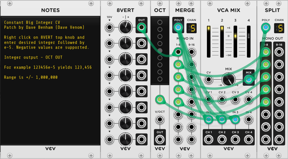
Constant Big Integer CV
Easily generate a precise integral constant voltage with a range of +/- 1,000,000
VCV Fundamental Constant Big Integer CV.vcvs (4.9 KB)
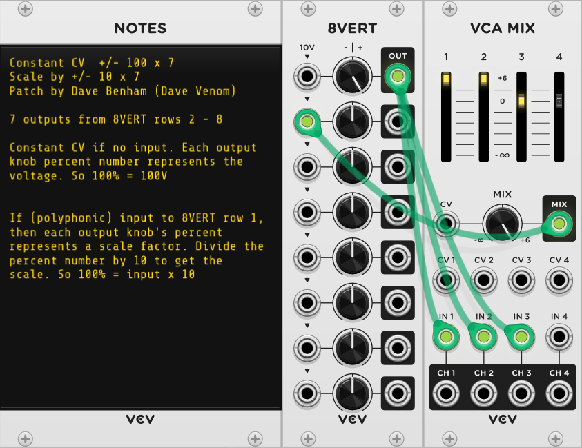
7 x Constant CV +/- 100 or Scale 10
- Generate up to 7 constant CV values with a range of +/- 100
or
- Multiply input (polyphony supported) by up to 7 different scale factors with range of +/- 10
This is especially convenient for Constant CV as the knob percent number equals the output voltage.
VCV Fundamental 7 x Constant CV 100 - Scale 10.vcvs (2.9 KB)
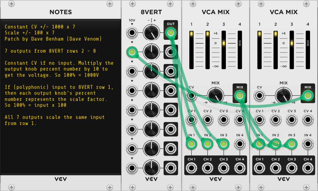
7 x Constant CV +/- 1000 or Scale 100
- Generate up to 7 constant CV values with a range of +/- 1000
or
- Multiply input (polyphony supported) by up to 7 different scale factors with range of +/- 100
This is especially convenient for Scaling input CV as the knob percent number equals the scale factor.
VCV Fundamental 7 x Constant CV 1000 - Scale 100.vcvs (4.1 KB)
Polyphonic Scale +/- 10
Scale any input (polyphony supported) by a constant factor ranging from -10 to 10, with option to add offset CV input before scaling. This is a simple and compact construct.
VCV Fundamental Polyphonic Scale 10.vcvs (2.4 KB)
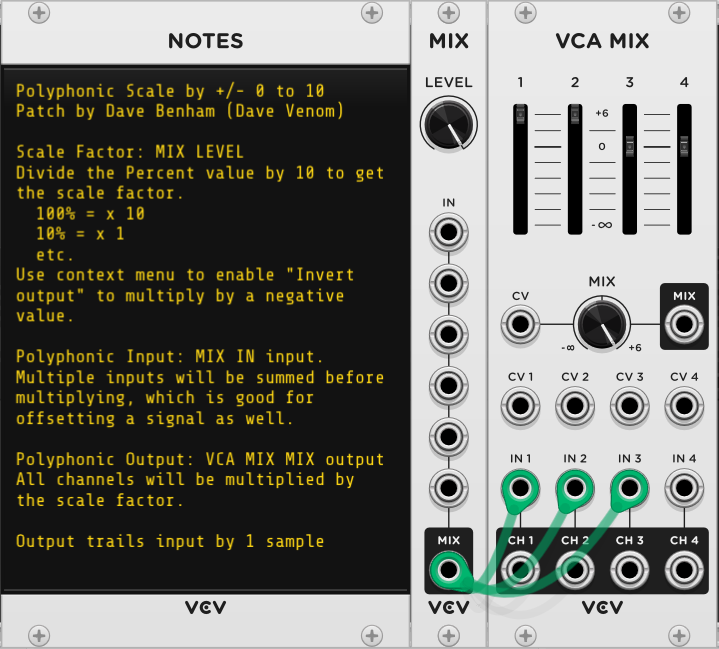
Polyphonic Scale +/- 100
Scale any input (polyphony supported) by a constant factor ranging from -100 to 100, with option to add offset CV input before scaling. This is nearly twice the size as the Scale 10, and the large scale factors are rarely needed, but it is very convenient to use because the knob percent number reads directly as the scale factor (100% = 100 x input)
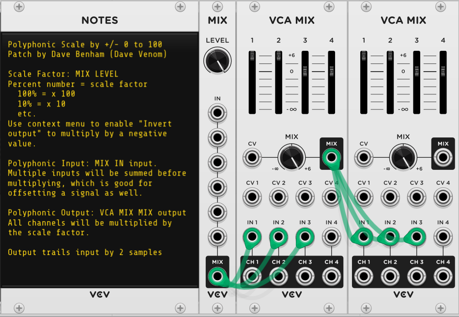
VCV Fundamental Polyphonic Scale 100.vcvs (3.7 KB)
Multiply A x B
Multiply A (clipped at +/- 20V) times B (unconstrained)
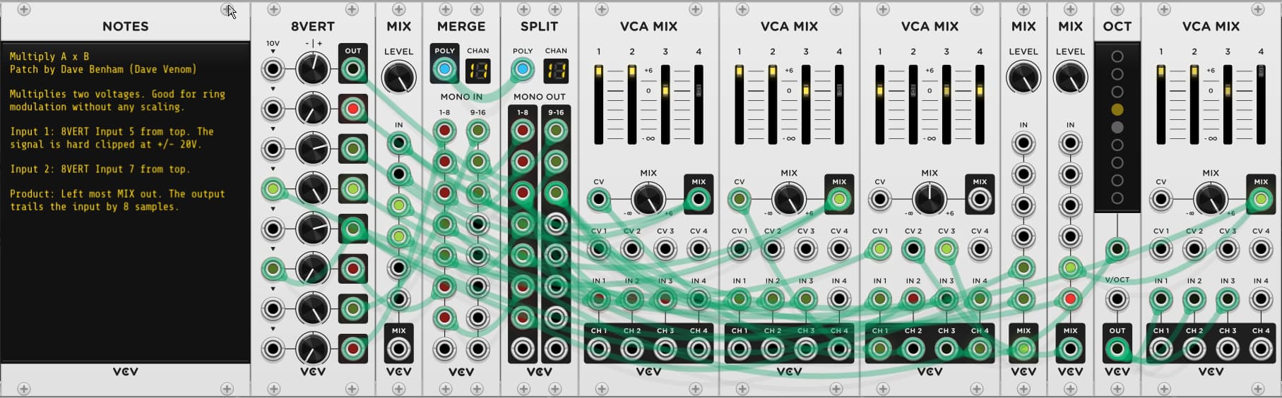
VCV Fundamental Multiply.vcvs (14.1 KB)