DIY Module Front panels (two questions and a big tangent)

An update on LPG and other stuff.

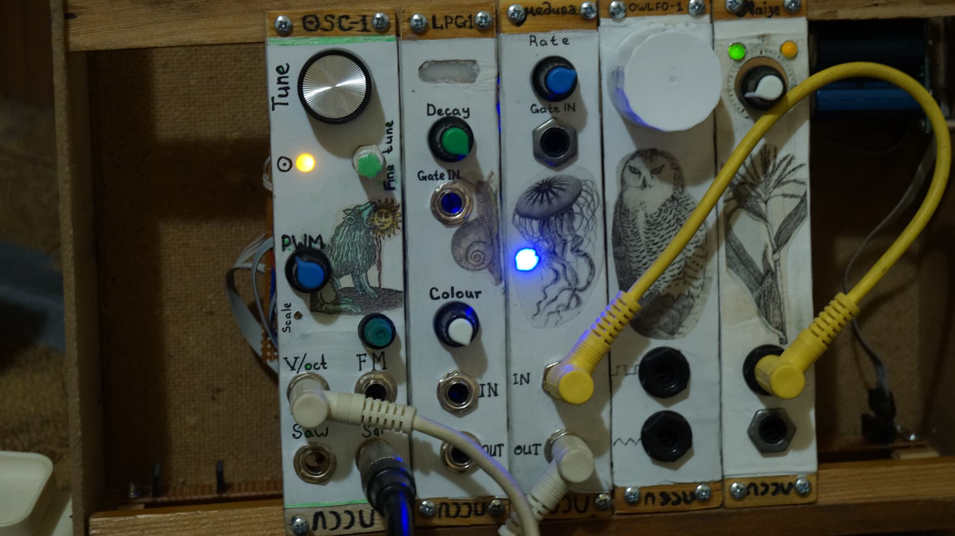
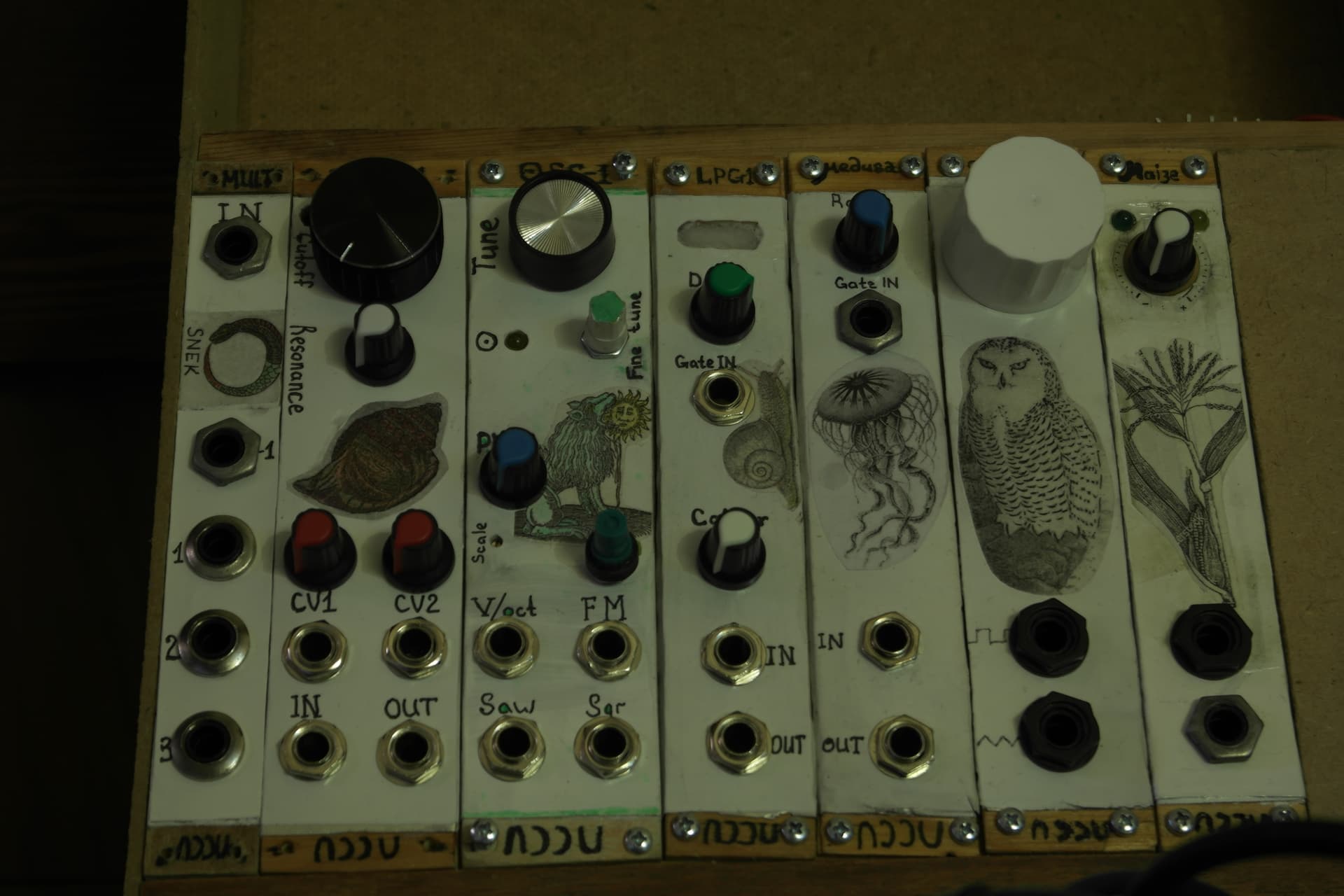
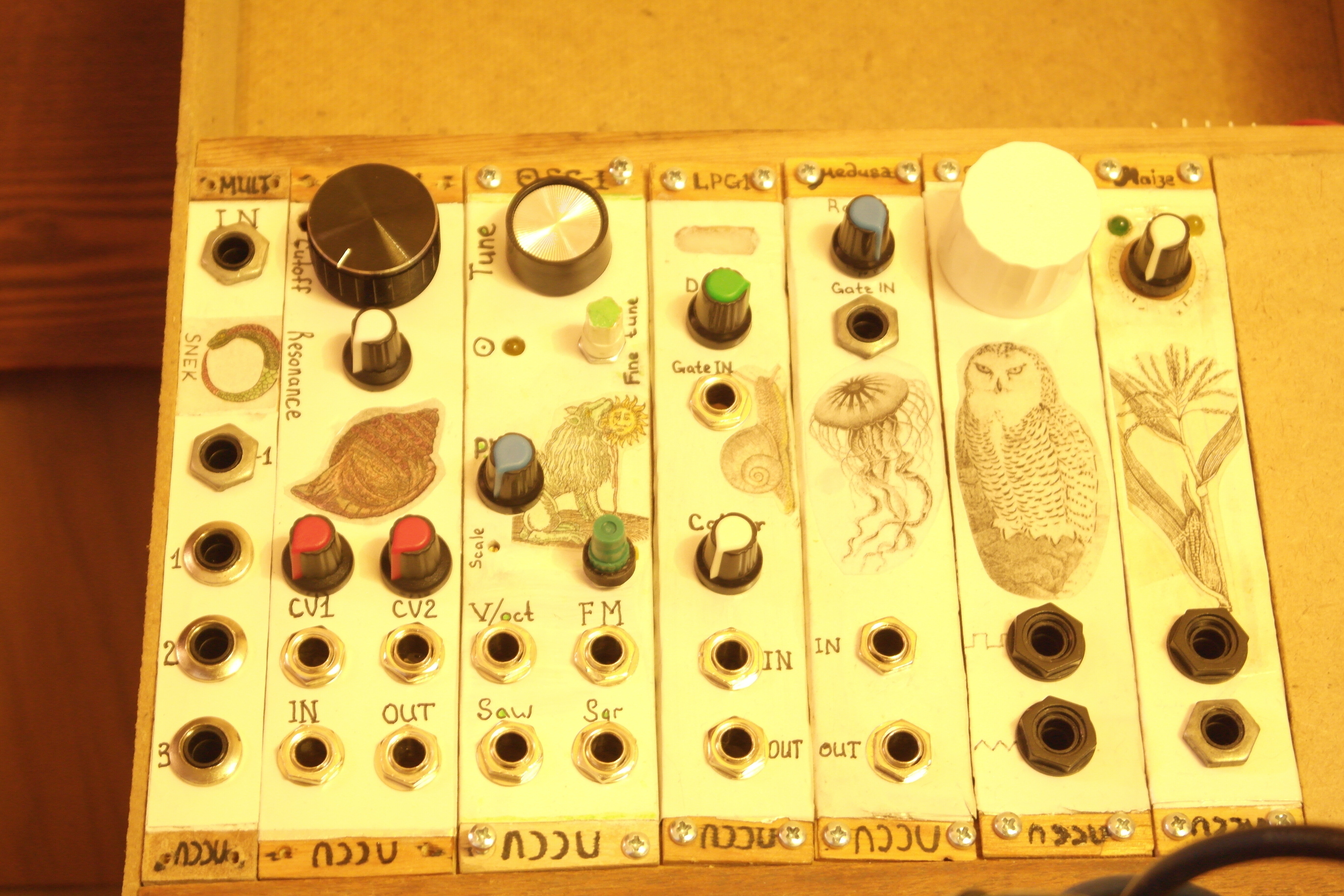
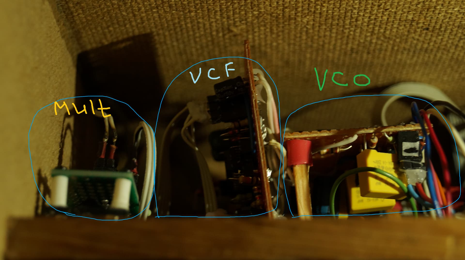
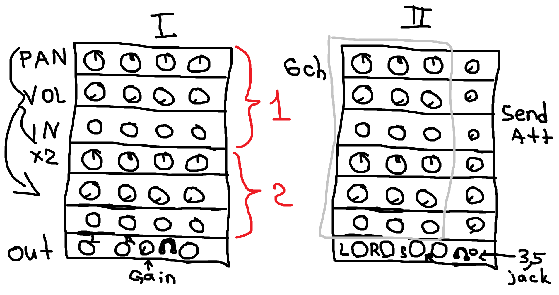
I redid most of the confusing wiring in my Oscillator project. Now it should go more smoothly, I hope. It still isn’t ideal, but I have noone to blame, yeah. Next time I would do it very differently.

I finally made a semi-proper power distribution line.

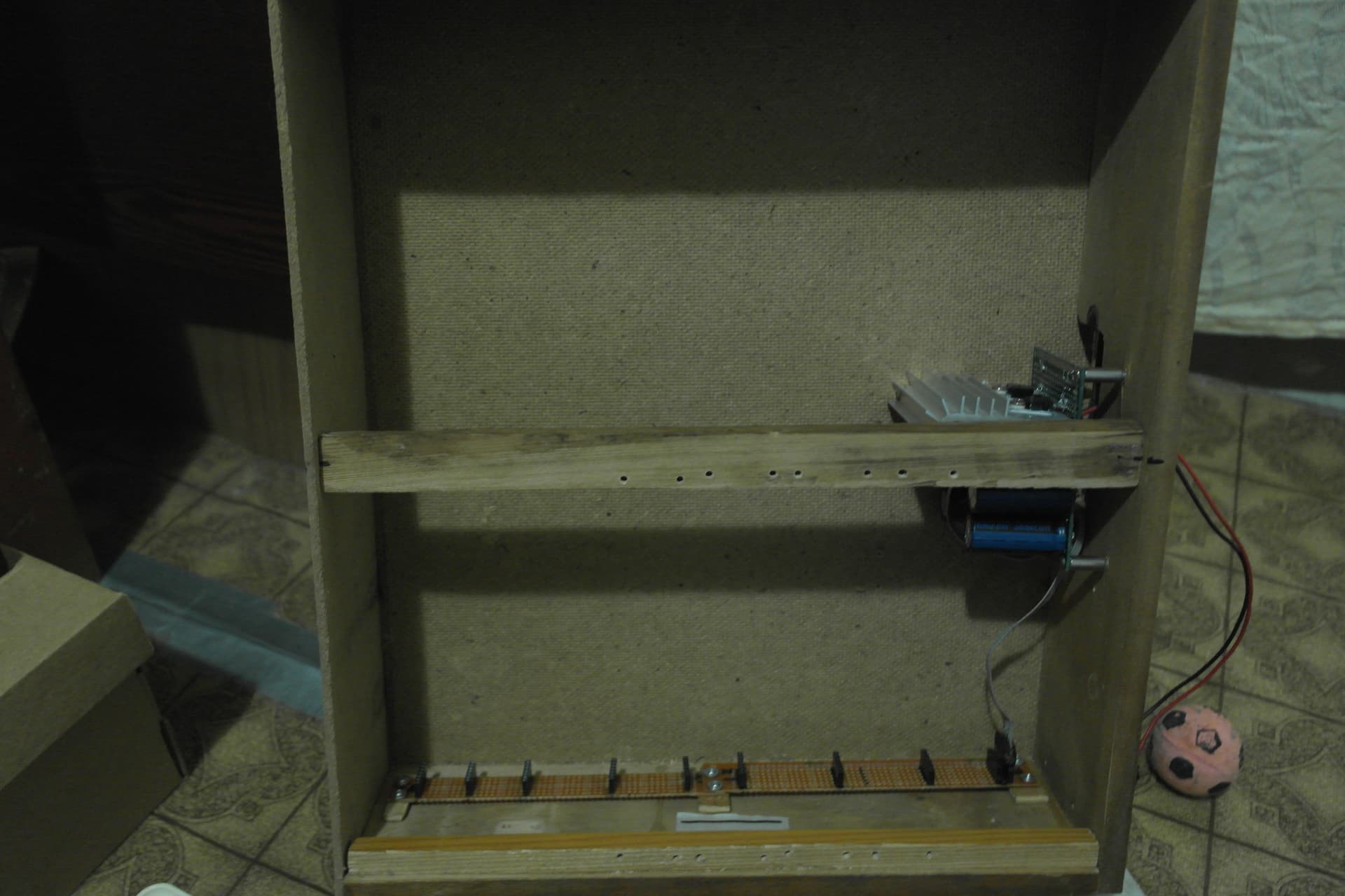
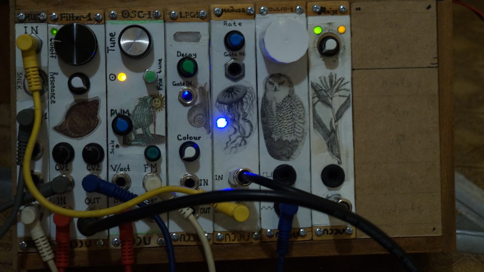
I did it at this stage, because before recently I wasn’t sure how many modules would fit there. Now I know! And I still miscounted it and added one extra connector, haha. But that’s fine! It’s even better, because it’s nice to have a spare connector in case something goes wrong.

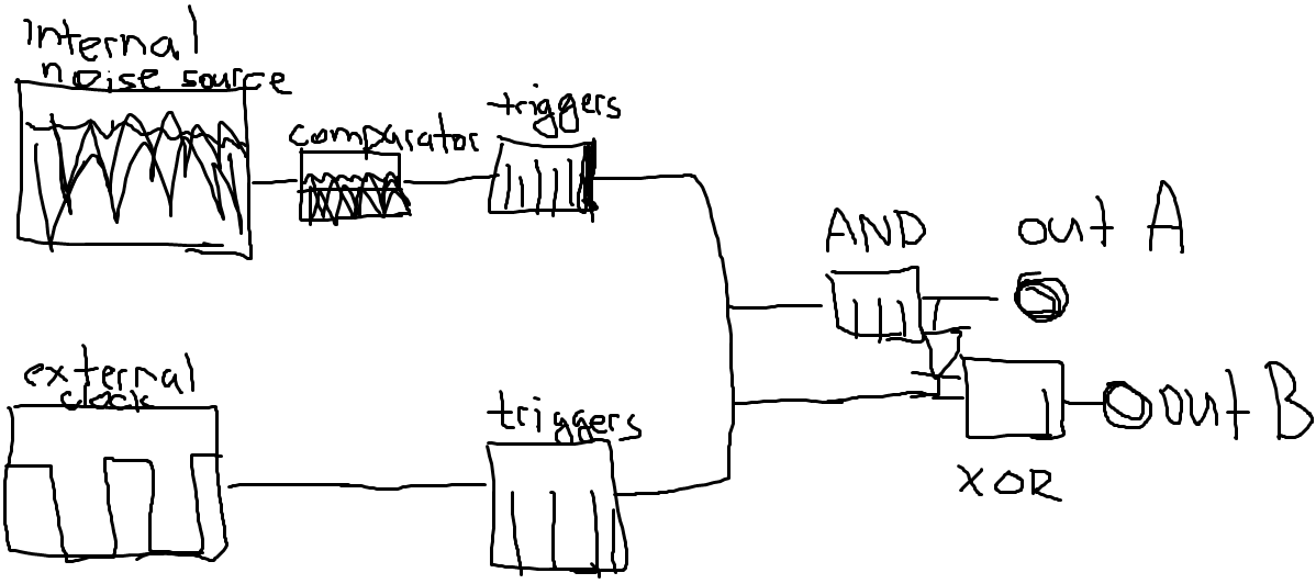
I don’t know if it is a good idea, but I am planning to make a very simple transistor logic module. I googled it and it’s so easy to build, so maybe I’ll make one just for kicks. Although before that I need something like a second LFO or a clock module… We’ll see!

PT2399 that I ordered got cancelled. I am not mad, but it was unfortunate. They gave me back my money, so everything’s fine. And I ordered another batch on Aliexpress (two lots, one is SMD… or SOP I don’t know if there’s a difference, I ordered it by mistake and it was too late to cancel the order when I noticed that), it should arrive in a month along with lots of potentiometers, few LM13700s, and one V3205D. Yeah, can’t wait to find at least one working chip there! Hopefully

I also ordered a Norton’s Op Amp at my local store, this one is for Tinkle by Nonlinearcircuits. And that’s also the reason why I started to think about logic modules. I wanted to build another NLC’s module for gate patterns, and maybe I will, but there are usually tons of CMOS stuff that I would have to order and use for this one thing only, just like this Norton’s op amp! I ordered two of them though, Who knows, maybe I would build another Tinkle. Or maybe I would use for something else.

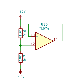
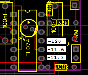
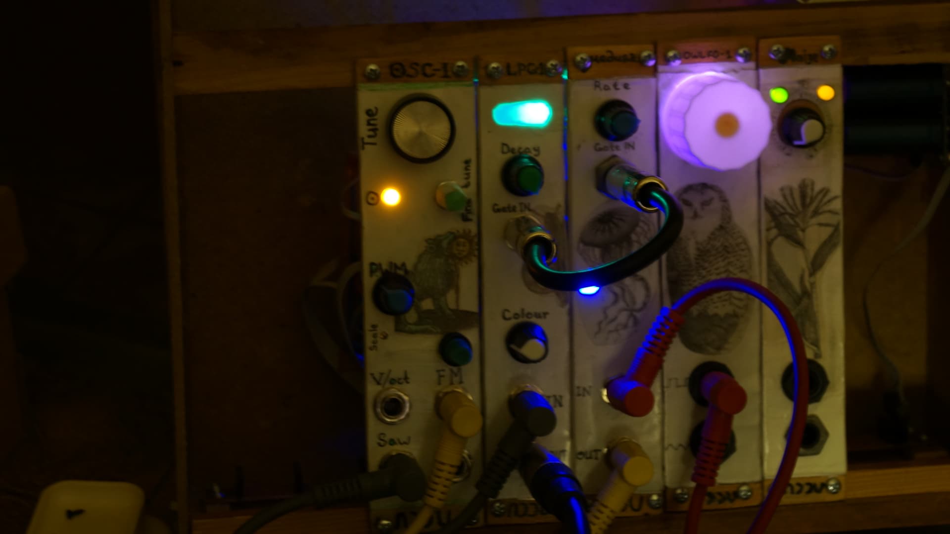
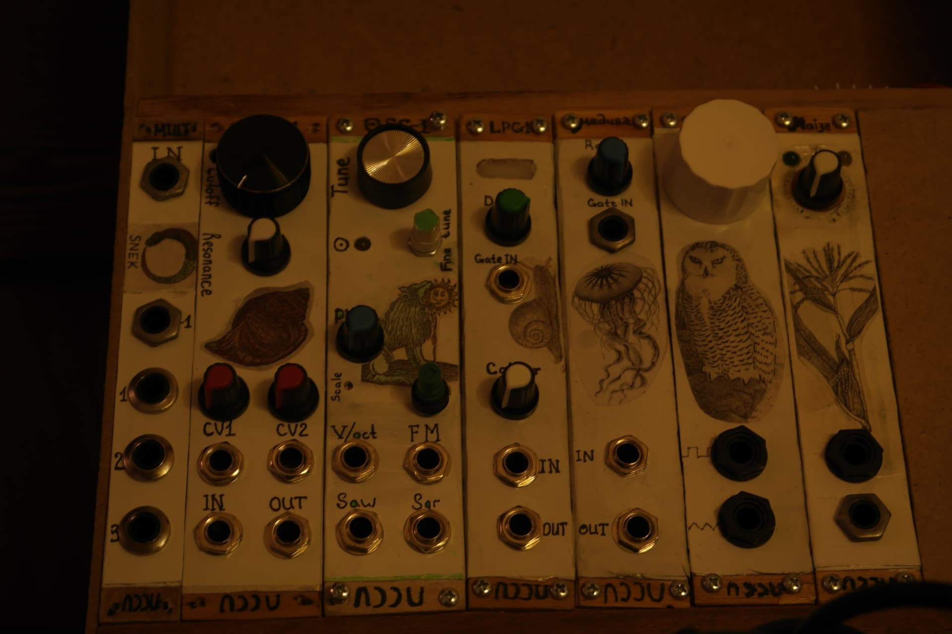
Now for the final news! Good news! Half a week earlier @Curlymorphic noticed that the input impedance on my LPG is 10k instead of usual 100k. So I changed it and now it works wonderfully! It accepts my LFO and anything, really. It’s the second time when I did something stupid and got caught, haha. First time was when @Jens.Peter.Nielsen noticed that I put a diode the wrong way round. This time though it wasn’t my (and easyEDA layout) mistake, it was some kind of ShedSynth’s thing, I guess. I looked at other ShedSynth circuits and it’s all consistent with 10k input 100R output impedance. I wonder if the reason was that there was a bag of 10k and 100 ohms resistors at their place and not so many of 100k and 1k. Ah, also a little update on my YASH external clock situation. I had a similar issue with this one. I just couldn’t use anything as an external gate source. And I still can’t power it with my LFO, but for some reason it now works happily with Microbrute’s LFO. It didn’t before. There’s no changes in a circuit, nothing, but it just works now. Very interesting. Looks like a loose connection that got fixed, at least for now. Maybe I should reflow everything… If I ever feel bored to death.

Anyway, that’s all! And here’s a cat!

1 Like

Sorry for my lack of replies, I have been decorating, and it is amazing how much more I can get done by simply unplugging my internet.

Looks like you are progressing nicely, and things are starting to work.

When you mentioned the lfo output was a voltage divider with a 50k output impedance, I knew that would cause problems, if you are interested I can draw a sketch and some simple maths to show what happens, but you may already know this, but you may have to wait a couple of days until I have pc setup, my eyes are too bad to do much on my phone.

The cat is looking good, and the addition of a second fur tone under the chin is a nice touch, Im sure many members of this forum also have a white beard, I know I do.

1 Like

Oh, that’s fine! This thread is intentionally very slow, so you (and anyone else) can reply even after a week or two and it would be fine too! And that’s if they even feel like replying at all. So yeah, not a problem with a lack of replies!

I do know this, but not from a mathematical side of things, more like it just feels wrong. So I am interested in maths here! And I won’t redo anything but I am also interested in how to rearrange the schematics to avoid this issue. I guess I would need a buffer and then 1k resistor to the output? It’s a really strange schematic now that I think about it… But there’s a reason why there’s 1 in the name of this module (OWLFO-1). Hahaha. I am planning to make a better one later. Probably an OWLFO-2.

Yeah! This cat has a real prototype, btw. I don’t remember where I saw him, but it was a very cute and friendly cat, that I remember. Also very big

Well, as long as it’s not blue…

1 Like

A small update and an alien tangent.

So I don’t know what’s wrong with the oscillator, but it just doesn’t work. The very first time I tried to plug it in my case, it killed the 40106. Shorted it, making my whole setup to freak out. LFO light got dimmer, YASH started to blink slower, or so it appeared… Of course I wasn’t sure if it was my fault or if it was a bad IC. So I changed the broken 40106 (I checked and it showed continuity across 7th to 14th pin. Bad news! New one was fine… was). Right, I changed it and yeah, shorted it. Good news is that it doesn’t show continuity from the power pins. But I am not sure if it’s alive… So I ordered 10 more!

Alright, so after revising the schematic I noticed that I really shouldn’t have done it while being sick. I mean even before I got to the soldering stage I did something stupid. It wasn’t too stupid, I missed one thing when copying Benjie Jiao schematic. Ah, I also noticed a weird thing with the unused op amp, so I wrote to Benjie and he was very nice, he explained that it was kind of rudiment from the previous stage of this project. And I could just send a pin to the ground. Nice

image

I suspect that my problem is with one of the transistors, believe it or not. I think I might’ve shorted it when testing the circuit while it was wrong. Just like I burnt my IC. I am not sure though. And it’s a pain to desolder transistors, I naively hoped that I wouldn’t need to change transistors, so I soldered them for good. You know, imagine like cementing them into place and also hammer them into that cement with a nail gun. Very secure! And very stupid. Of course I exaggerate it… a bit. It would be a problem to desolder it, but it’s not impossible. But it’s such a chore… I don’t want to. Not now, at least. Maybe I should redo the whole schematic. And then redo the layout and then redo the board. And this one… I don’t know. Imagine after 1000 years aliens would visit our planet and they’d steal this thing from my tomb with all the Indiana Jones traps and crystal skulls and all that. They might try to power it on. And then it would destroy their spaceship. I am so sorry, aliens.

So now my plan is to debug this module and while I am trying to do that, I am thinking about building Rene Schmitz’s 4069 oscillator. It looks easier and… just fun. I know that it drifts like crazy, but… for now it’s alright. And it has its charm. Imagine aliens hearing this drift! They would be like “Oh hell, sounds cool”. And one of them would say: “I told you it was real! My grandpa once caught a radio transmission from this place and it was funky and weird”. “We believe you, John” - his name is John. - “And that’s why we are promoting you! Now you are not just John, you are Jonathan!”. He’ll probably cry. I would if someone suddenly promoted me to Andrenathan, I would cry like a baby.

Anyways! I don’t think anyone might help me with this, so I am not posting photos and schematics… But the faceplate is very nice! If I suddenly get this to work, I would post it here and you might say something like “Oh wow, that’s cool! We are immediately promoting you to Andrenathan”. We’ll see though… It might be what they call a lost cause. And the faceplate would be just another thing for aliens to uncover…

That’s all for now. No cats, no nothing… Next time there might be cats!

1 Like

Small point. to ground pin 12 of that unused opamp it would be slightly better to connect it to a real ground, rather than the psuedo ground made with r16 and r17. Nothing bad with what you did - just adds two resistors and draws perhaps a milliamp of wasted current.

1 Like

Yeah! That’s not what I did, that was in Benjie Jiao’s schematic and I was confused a bit, so I wrote him and he said exactly what you said just now, haha. Like, just connect the 12th pin to the ground. And so I did! I was relieved, cause it was a bit crowded there, so deleting two resistors from the schematic was very appreciated. Thank for you advice though! If I haven’t contacted Benjie, I would be probably still a bit confused

2 Likes

Alright! Very eventful day!

First things first, while I was planning on making the 4069 VCO, I managed to fix most of the bugs in 40106 VCO and now it actually works! What was wrong? Everything that I already mentioned and one extra bug, or more like a blunder.

  1. As I told you before, my soldering flux conducts electricity. I discovered it while fixing the bugs with… YASH, I think.I don’t really remember now. But it conducts electricity like crazy. Like a metal plate almost. So you have to be extra diligent when cleaning the board. Extra effort wasn’t ever my thing, so I was just cleaning it with the toothbrush twice on each side. Well, it turns out that wasn’t enough. So I had one extra 40106 and I decided to try and fix the oscillator. If not then alright, I have 4069 VCO planned anyway. SO if it burns my IC, it’s not the end of the world. I decided to check ICs (there are two of them, 40106 and TL074) separately. I put the first one, 40106 - no blue smoke, no weirdness from my other modules, no short - everything is alright! Well, so the problem is not with transistors, I thought, but with TL074! So I checked the pins of an IC slot, the IC panel - whatever you call it and it showed me this on the right side (sorry for this messy layout):

image

Well, that’s not right! It shouldn’t show me anything like this. And I immediately knew what’s wrong. SO I washed it twice again. Now it showed 3v at the 10th pin. Washed it again. 0.5v. Alright. As good as It gets, I guess.

  1. Put TL074 - got some weird noises. Like splashes of something similar to red noise almost. Well, let’s put another op amp. Maybe I put the broken one by mistake (the one that almost melted my brain when I was testing LPG). Changed it - now it actually got silent. So I started turning the knobs…

  2. …and here’s a sound! But the usable area was very narrow. Alright, maybe I put a large trimmer or… Yes, I soldered the Scale wire on FM input and FM input wire on a trimmer. Fixed it and… well, the area is almost fine. It is usable! I put it in my case and started playing with it. Drifts like crazy, but I am a very happy man. Tomorrow I need to thermally couple the transistors and everything should be better. Not perfect, of course, but better!

So for the faceplate I picked a picture from an alchemy book. That was published anonymously in 16th century. It’s called Rosarium Blahblahblah something something - here’s a link. The picture is of a green lion that eats the Sun. Usually it’s interpreted as wild side of a person that destructs the Ego and makes the new Ego appear. To me it’s like… green lion that eats the Sun. It’s cool! Seriously though, I think it means the change of an era, destruction of routine. And there’s no new Sun here, so there’s no new routine. Yay! Or is it?..

And now for something completely different (not really), today I received a package from ALiexpress with this:

5 PT2399 (DIP)

10 PT2399 (smd) + 10 adapters smd to dip, cause I don’t think I will do anything with just SMD in the nearest future.

1 V3205D

5 LM13700 (should’ve ordered more of them)

and a whole bunch of pots.

I’m set for a very spacy delay stuff… Well, if all of these ICs work as intended. Which is a rare thing apparently. First thing that I’ll try would be probably Delay by Benjie Jiao again. I am ready to spend one of my PT2399s on this. Then I think I’ll try something different. Something… more spacy! Probably ABDUCTOR DELAY PEDAL by deadastronautfx, reimagined for modular. But I have my plans and it looks like I’ll start with Benjie’s delay… probably in few months. Cause I need VCA and VCF and mixer and sequencer and… Lots and lots of things. Maybe all the effect modules would need another case. But it’s good to have all the ICs now.

Alright! That’;s all for now. No cats again, cause I am sleepy and have to go

1 Like

I may have missed this, but are you using a rosin core electronics solder. I don’t remember ever having problems with the rosin flux being conductive, but I do remember it being corrosive and needed to be cleaned off of the board.

1 Like

I am actually not sure if it has any rosin… It doesn’t smell like it. I also have just rosin and another flux, this one is rosin based and it smells differently. This one, the internet says, is based on ZnCi2 and FeCL3, and yes, I only tried to google it just now, haha. It’s called ZIL-2, a weird russian flux. But I like how thick it is. ANother flux, trhat is rosin based, is much more fluid and it’s a pain, cause it just flows like a river, it goes everywhere

1 Like

In my experience, there is real art and practice required for soldering electronics. The key is to use as low of a power soldering iron as possible, with as small of a tip as possible and always use rosin core solder. Any other type of flux is going to cause serious problems, either immediately after soldering or over time as the acid fluxes will eat away the circuit board copper traces and other electrical wiring, pins and leads.

Use the finest gauge solder you can find also. Flowing solder is a must. If you end up with a glob of solder, it is very likely to result in either “cold” solder connections or shorts.

My formal training in soldering occurred in the 60s in high school where I took a vocational electronics class. We were taught to use high wattage solder “guns” which worked great on vacuum tube TV electronics but which absolutely did not work on semiconductor circuits. It took me a while to unlearn that.

My current solder station is a Weller WLC100 40W heater and using a fine pointed tip. Having a wet sponge tip cleaner is very important, although a wet paper towel can work also. Clean your tip often. Set the temperature control to as low as possible that will easily melt solder when directly applied to the tip. The tip must be “tinned”.

Sorry for being so wordy. You probably know all of this and may be limited in what you can find and afford. But, a good quality soldering station and a multimeter are a must. A logic probe can usually be used for measuring continuity.

When it is set up correctly, soldering is a beautiful experience :grinning:

2 Likes

Thanks! Yeah, I know most of this stuff. I can’t afford a good solder station (at least yet), so I am using a cheap chinese 30w iron. It works fine. I also have old soviet irons, but they are too big and powerful. It’s great for desoldering stuff though. You can just touch a board and everything falls off from it, hahaha. Well, not exactly like that, but it’s very powerful. Something like 90w. I think. I had 60w and 75w, but I shorted it somehow. Not sure what happened exactly. Probably there was a crack in the isolation. And since both of them are like… 60 years old now, it doesn’t surprise me at all

I couldn’t find it here. And I have lots of old solder. Like 5kg of that stuff. And it works fine, again. I bet rosin core solder would be much better, but for now I am happy with just regular solder.

So thanks! It’s really useful information! And I am certainly not a master of soldering yet, haha, so I will remember your advices! And search for all the good stuff one day. Maybe soon!

That’s certainly true! I don’t know why my flux us so weird. I use it in moderation, I usually apply it with a brush. Just one little drop of this thing… But it seems like even in this quantity there’s enough of conductive material… And I don’t know of any long term effect yet… Maybe it will eat away all the metal there. I’ll search for another flux soon! Rosin based, but more thick. If there is one…

My synthesizer were mainly made with wire wrap, not soldering. I guess it was easier that way.

1 Like

Yeah, most of my prototype projects were done via wire wrap. My first attempts at building a MIDI board was done in this way. I quit messing with that though after corrupting my new 10MB HDD twice due to errant assembly language “drivers” and interrupt handling.

In later years, I would buy a prototype board (the white socketed board that wires could be inserted into) and dedicate the board to that project. I’ve still got a box of those that I have no idea any longer what they do :wink:

1 Like

A little update:

I am planning to make two modules. One is Vactrol VCF by Skull and Circuits (I added an extra CV input just for funs). And the other one is very simple mult. It has one input, 3 buffered outputs and 1 inverted one, just to make it more interesting…

I already made faceplates or front panels or whatever… It looks like this: [two modules on the left]

Sorry if it looks a bit dark, but I am a vampire, it’s hard to take photos in my tomb, illuminated with candles and glowing mushrooms. Well, seriously though, it’s more about my Samsung NX1000, I think the shutter motor is slower than it should be, so I took a bunch of photos with different shutter speeds (almost blindly, cause it’s unpredictable) and this one was the best one. Other pictures, just if you are curious (I changed the white balance… eventually):

And the problem with my Sony a37 is that… I don’t know. There are no problems, to be honest. I could’ve used that camera instead. But I like to shoot with 100 ISO, and there wasn’t enough light on this setting… So photos were a bit blurry, I need to make a remote shutter for this camera… Anyway! Back to the modules!

Mult faceplate is made with… I don’t know what you call it. It’s a thin fibre board. Like this:

image

I tried to use plywood, but it broke, it’s just too narrow, I think, so it breaks easily. This fibre board though is thinner than my piece of plywood and It’s easier to drill holes through it. But there’s a downside: it’s dusty and it’s hard to glue something on it. The smooth side is just bad for this, but the fibre side is pretty much unglueable. And also it absorbs the glue and it creates some kind of bulges… Yeah… I have another piece of this material and it fits perfectly to the right of the modules. I want to make a mixer there. And I probably would use this fibre board again. But I should experiment before that, to make it more suited for the purpose.

To other news:

I ordered 3 arduino-like controllers on Aliexpress (LGT8F328P-LQFP32), I have some plans to make this and that… And no experience of working with Arduinos and whatevers elses. I think it should be easy. It’s not assembler or something, right… Right?

I also ordered some sketchy BBD chips. MN3208 with MN3102 drivers. And also a batch of sketchy J112. Two sketchy XR2206CP and LF442CN. This last one is the least sketchy, to be fair. I am almost sure about TL072 and I have hopes that LM13700 will be real (last batch I bought turned out to be okay, though I only tested it with my DMM against the one that is 100% real. It shows very similar numbers).

My friend promised me Arduino Micro for my birthday, which was a week ago, but he lives in another city, so I don’t know when I would have time and money to travel there, and he doesn’t know when he would be here… So we’ll see. Maybe I would receive my chinese controllers first.

Anyway, that was an update. Nothing really interesting. There would be better photos and maybe even sounds next time. No promises though.

Here’s a cat!

1 Like

Cats looking good, and the promise of sounds is even better, you are flying with these modules now, and that box will be making all sorts of strange noises soon enough.

Arduino type microcontrollers can be cool for experimenting with CV and Logic, just protect the inputs, they don’t seem to like anything outside the 0 to 5v, or 0 to 3,.3v range, to get started a resistor and a couple of shunt diodes can go a long way.

1 Like

It already does, haha. But it would be even stranger!

Yeaah! Well, I think of making a quantizer with it. I know that there is a way of doing it without any microcontrollers, even with adc-dac conversion, I think, it’s possible. But I am not really a masochist… I also want to make something like Branches by Mutable Instruments, also a good digital clock would be great… And then I’ll look into granular stuff and CV to MIDI stuff. It all depends on what can be found in the internet, haha. And on what is possible to do with these chinese controllers. They seem good enough though.

Ooh, good to know! Well, I was expecting that to be the case, cause their power supply should be 5v. So it’s fair that they would be sad if you feed more than 5v (or less than 0v) into one of the inputs.

1 Like

A little update and a question, or maybe two or three… We’ll see!

So first of all, an update - I finished multiples few days ago and now building Vactrol VCF by Skull&Circuits. It’s pretty easy, but my workflow is always kinda slow and relaxed, so maybe by monday I would finish it. Maybe later though… Anyway, that’s all for the updates

So now a question - is there a way to build something like Bernoulli Gates without microcontrollers? I mean, I know that there is a way, but maybe there’s an even simpler way… What I am thinking is, let me draw what I think should be a fully analog Bernoulli Gates thingy

Of course I am not building this, not at this stage, hahaha. But it looks… fine to me. And I wonder if there is an even simpler way of doing it… But every time it kind of comes to a problem with sources of randomness and how to control them… And I clearly lack any knowledge in this sorta sphere. This design or algorithm is probably what is happening in Bernoulli Gates…Or I think so, I haven’t looked into the code of this thing. I think it’s open source, so maybe I should try and follow it. But It’s probably C++… I am a novice in C, but with C++ I am a noob, I don’t even know if they are different or not, hahaha, but my instinct says that they are…Otherwise it wouldn’t be called C++, it would be called C. Also C#, what is it? Never tried to read about it. Why it’s called C#? Why not Db? So many questions…

Another thing I was wondering about (maybe it’s too early though) - would there be any problems with microcontroller-based modules if I disconnect the power for my modular just by plugging a cord, like I usually do now. Should I make a power on\off switch for each such module or for the whole system? Or not and It’s totally fine to unplug the modular this way? I mean, I was thinking about making a power on\off switch for the whole system, but I was thinking where it should go - before the PSU or between PSU and power distribution? My instinct again says that it’s better to suddenly load the PSU, cause it should manage it, than to suddenly switch on all the modules… It just feels wrong… Yeah. Hope someone has answers, hahaha. Cause I am very much interested!

It is a bit creepy when your project works as intended right away. So first time it happened with Mult. I made it very quickly and expected a lot of problems. And I was relieved when it appeared that it is broken. Though later turned out that i plugged it in my power line the wrong way round. I have to do something with this problem. Maybe I should make a symmetrical power lines… I don’t know. Anyway. I re-plugged it and it worked! Well, alright, VCF is much more delicate module, this one should produce some problems to solve!

And it did, but not the way I was expecting. Well, it was an easy build, of course, and it worked right away, as I hinted before. I just had to tweak the trimmers (it has three of them, for the offset, range and resonance\feedback) and it started producing interesting sounds. I like it very much! But the problem appeared when I tried to put it into the case. To the left there’s a Mult module that is not deep and provides a lot of space for the VCF circuit board to feel comfortable. But i was stupid and I drilled a hole for the LED on the left side of the module. And… well, all the front panel stuff is kinda leaning to the left a bit. So it was very hard to fit the wooden plank that I will connect the board to. And this plank should be kinda thick, so it wouldn’t snap or anything. So yeah, had to glue it on the right side of the front panel. And there’s VCO to the right, it is deep and it a bit crooked, so it actually kind of bulges to the left. Anyway, here’s a photo:

As you see, I had to attach the VCF board with a slight angle. Well, it works! But with all this space issues I managed to somehow break my LPG. Not break exactly, but I think… Alright! Here’s what I think happened: VCF pushed VCO, and then VCO pushed LPG against YASH. So now you can hear YASH oscillator through the LPG output. And it catches noises and bypasses the circuitry. So yeah, something is shorted there. I have to check, but to do that I have to unscrew at least two other modules, cause It’s too tight there, I can’t just unplug it from a power rail, or I can actually, but then I would have to plug it in again and that would be very difficult.

Anyway. A short video for you! I filmed three different patches and wanted to edit it into one video, but it turns out I have DaVinci Resolve installed on my other HDD (that I disconnected for now). Sorry!

Some extra photos (the last one I used for the video thumbnail):

1 Like

A little update (with a low effort cat drawing at the end)

For now I am waiting for a package from AliEx and drawing schematics/making layouts for my next modules. I also became quite aware of the space issue. I don’t have much space in this case, so I am thinking about making another case. Maybe I’ll make it out of an old plywood suitcase, actually. I would be very convenient to carry anywhere! And it has a lid or what you call it. There are problems with this plan. The biggest one is actually another type of space issue. Depth! It not too deep. Not deep at all. My present case is about 8cm deep. My ruler says it’s somewhere around 3 centifeet? Millifeet? Inches! Right. It’s like 3 inches and one bigger line after that mark. So it’s 3 centifeet and 1 millifeet. Okay. But the new case depth would be about 65mm or 6,5cm. That 1,5cm less. So the difference in imperial would be… man, I don’t know. A bit more than half an inch, like 50-60 millifeet. I hope I explained it well! Anyway, it looks like nothing, but it’s actually a lot. For example, I would need a power supply there and It should be mounted somehow. So the problem is that my capacitors for PSU are about 6cm. I think I can buy shorter ones, but just to illustrate my point - PSU alone would take a lot of space no matter how I place it in our beloved three dimensional universe (even if I buy smaller caps). And after that I would have to think extra hard about wiring and modules’ placement and all that. Do I want that or do I want to make a new case from scratch, which is also a pain, cause yous know how I love woodwork… Maybe I should raise it a bit… Or I don’t know. I don’t know. But that’s my newest problem! And I haven’t even finished with the previous case. The present one. The whole upper row is free for now. And at the bottom there’s a gap for a mixer. And that is a nice transition to the next topic!

So I am planning to make a stereo mixer. That’s not very complicated. But I also want to maybe add a send\return path there. At least I am thinking about it. So I started googling and I found Ray Wilson’s schematic. A very nice module, but I have a big problem with Ray Wilson’s schematics. They are unreadable. To me anyways. It looks like a maze, it feels like a maze and I just can’t be bothered figuring all that stuff out. Huge pain in the ass. And to make thing worse he had a habit of separating the schematic, dividing it to two or three or even four lists. The stuff is unreadable! Well, to me anyways. I respect him, but his graphic skills is a mess. It reminds me of the times when you had to draw everything on one list of a given size, a standard A3 or A2 or A1. So you draw a plan of a building and you see some space left and you think “Ah! I can put some additional stuff here, like how to fasten an emergency ladder to the wall of a building”. Well, these times left! Even when Ray was alive, we had a lot of software and a lot of paper… And he was doing it on PC anyways, so there’s no problem with paper… Sorry for this roast. He was a genius, but his schematic graphic designs are killing me…

Right, so if you know any good stereomixers with send/return paths, speaker outputs (I also want to switch between 4ohm and 8ohm speakers, so I am interested in both, I’ll try to combine them in some way) and more… clear schematic - please share. I have seen some of them on reddit, but mostly it was work in progress. With no updates for years. I suspect that these projects were abandoned.

Maybe I should go with just plain 8 channel stereo mixer… But it feels like 8 channels are a bit too much. That’s why I though that 6 channels and send/return would be better. So there are two ways of doing it, front panel design-wise:

I also can make it 5 channel mixer and put the send/return sockets on the second half of a mixer. It would make space for a gain or volume knob… So that’s what I am thinking about when trying to fall asleep, haha. Meanwhile I am also planning to make a very simple mono mixer. For CV and all the midway audio processing. Like if you want to send two signals to the filter or something. I do it a lot in VCV with pseudopolyphonic chords (I mean it’s not pseudo-, but it’s not VCV polyphony, I just combine few VCOs playing different notes together), I also do it with drums a lot. So that’s needed… You see why I am suddenly concerned with space in the case? Haha.

A promised cat!

1 Like

Not much happened in these two weeks. I was waiting for Aliexpress. Which is not an express at all, as one of my friends said. Received the package today. I am not sure if you are interested, but I’ll list everything interesting I’ve got… Gotten? Geticht? Goturgen? What the hell, english is hard. Anyway, here we go!

  1. LF442. I don’t remember why I ordered it. I think it’s an op amp. It probably has something to do with the next item!
  2. XR2206. I wanted to make some kind of an oscillator. I can’t remember what kind of schematic I had in mind though. It was based on you know what, of course. But I think it wasn’t the original one. So I have to search for it again. Maybe it was NLC…
  3. Bunch of 7555s. Again, I don’t remember what I wanted to do with them. Maybe envelope generators… Maybe an oscillator… Maybe something else. Who knows? I ordered it one month ago. I am much older and wiser now! And my memory is less strong…
  4. MN3208 and MN3102. So I was thinking about making a Karplus-Strong VCO. And I ordered MN3208s, 5 of them. And later I realized that I need MN3102 to drive it. So I ordered it as well. Interesting story! All true.
  5. LM13700s. Well, there’s no such thing as too many 13700s, I think
  6. TL072s and TL074s. Never too many, again. Especially given that the cause of my two week hiatus is actually that I ran out of TL072s. So I bought 20 of them. I don’t need them as much as I need 074, but… never too many, yes.
  7. J112s. Tested it. It is indeed J112. I had J111, which turned out to be something different, I think. Or I killed it by mistake. Anyway, now I have a bunch of J112s and I can make jfet sample and hold. Just because I can! Not now though…
  8. Couple of cheap chinese MCUs. I now have some kind of clone of Arduino that was given to me by my friend. But when that happened I already ordered three chinese MCUs (LGT8F328P-LQFP32) and I still think that it’s not much. I need more. So I ordered one bluepill and one Seeeduino Xiao for my further experiments. And I really want to somehow get the Daisy MCU. It looks cool. Can’t buy it though
  9. Not really interesting stuff: 6pin pots and audio (log) pots and jack sockets and of course LEDs. That’s why we are all doing it, right? Beautiful blinking lights! The whole reason to it.

And that’s all for now! It’s more like an “I’m alive” post. Cat!

1 Like