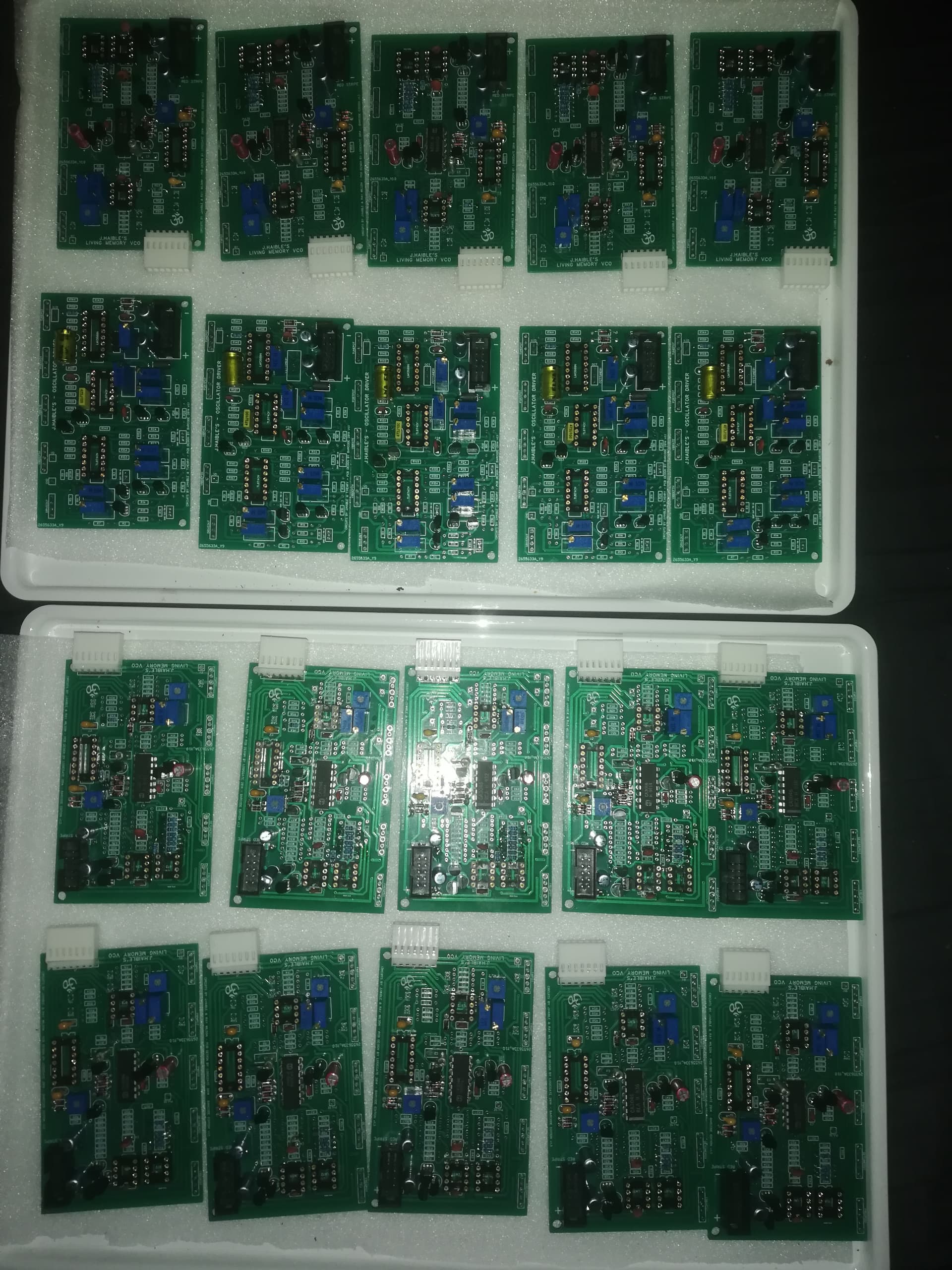
Various components not soldered yet.
1 Like
Oh wow! Lots of trimmers!
Yes, 85 ![]()
(100 even. )
1 Like
Haha… And I am losing patience with only two of them…
Yeah, 555 was awful in that respect. I banished them from my neurophysiology lab in the 70’s.
2 Likes
We have come a long way… By the way, Gordon Moore died.
Last week I was determined to make an oscillator module and I even started making it, but I also wanted to make a very simple LPG module. I wanted it to be non-resonant, one vactrol - very basic thing, just to have some kind of VCA-ish module in my rack. And I made it in one day. It was very easy. And it didn’t work, hahaha, so I moved on with the oscillator, but then, while making it, I suddenly got sick. Not sick of making modules or anything, just sick. I was bedridden for two days, slept for 35 hours or something like that. And when I got better, i understood that it was a very bad idea trying to proceed with building an oscillator in that state, hahaha. The board looked like a nightmare, so I returned to my faulty LPG.
After visually checking the board and schematic for anything out of order I took my multimeter and checked the components, on board - yes. Here’s my easyEDA project:
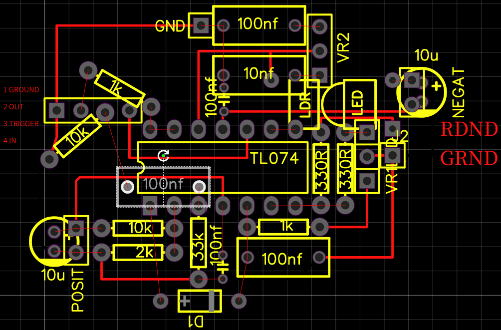
See the highlighted (more like graylighted) capacitor? It showed me 200nF capacitance. Not cool! I was considering to desolder it and check again, but then I just decided to take out the TL074. Et voila, 100nF. Put it in - 200nF. Wtf. After all that I just took another TL074 and yeah, now it showed me 100nF. The previous one was faulty! The first faulty op amp in my projects, let’s celebrate! I can’t be bothered thinking what was wrong with it and why it messed up the capacitor reading. Maybe later…
But it can’t be this easy, of course, something is still wrong with this module. It works with the raw clock output of YASH: I just put the jack into the input without disconnecting the trace, like this
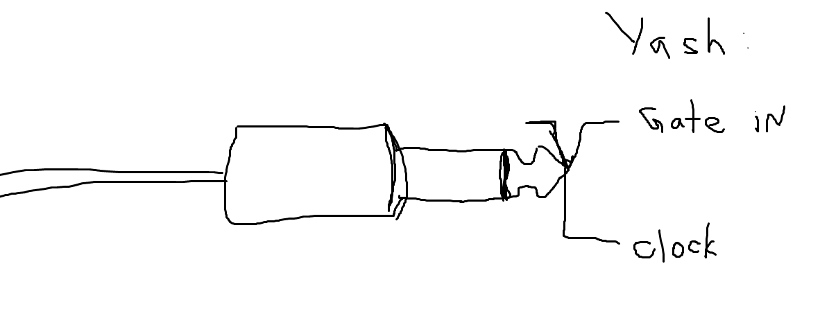
It works with the Grain Noise output of Noise Cornucopia, It works with LFO from my Arturia Microbrute. But it doesn’t work with my LFO or with Gate Out of Arturia. I think that my LFO is maybe too weak, the current is too small. It should be buffered, but who knows… Something is definitely not fine. It’s weird that Arturia’s Gate Out also doesn’t trigger the LPG. It could be some ground issues, maybe the capacitor has to receive the negative voltage to reset and with Gate Out it receives 0-10v… But again, if you wait a minute for capacitor to discharge and send the Gate it still won’t do anything… It could be that I messed up with diode again (I am pretty sure I didn’t though) and Gate input waits for the negative voltage. It would also explain why it works with LFO and raw (bipolar) clock output of Yash. Yeah… Idk, idk, idk. For now I am happy it works at all, even if I have to put some duct tape on it, figuratively speaking.
And now some photos! Finally!
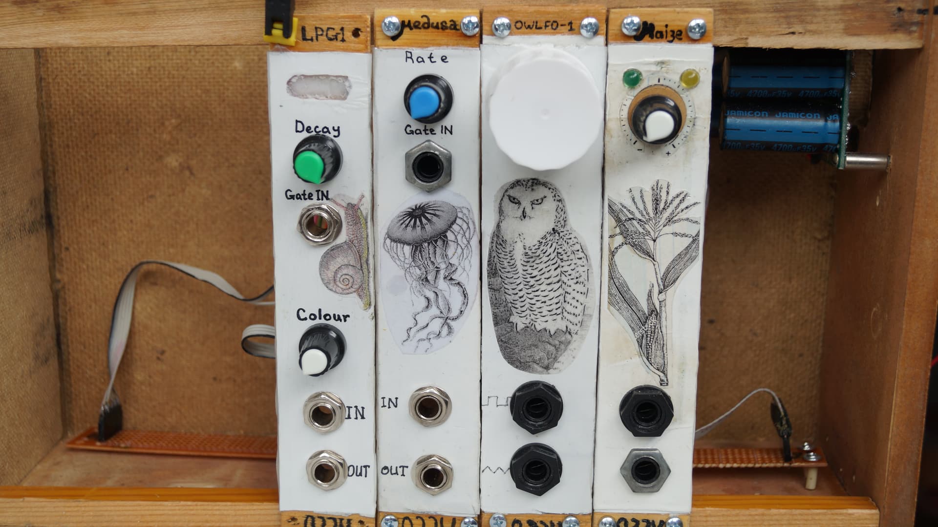
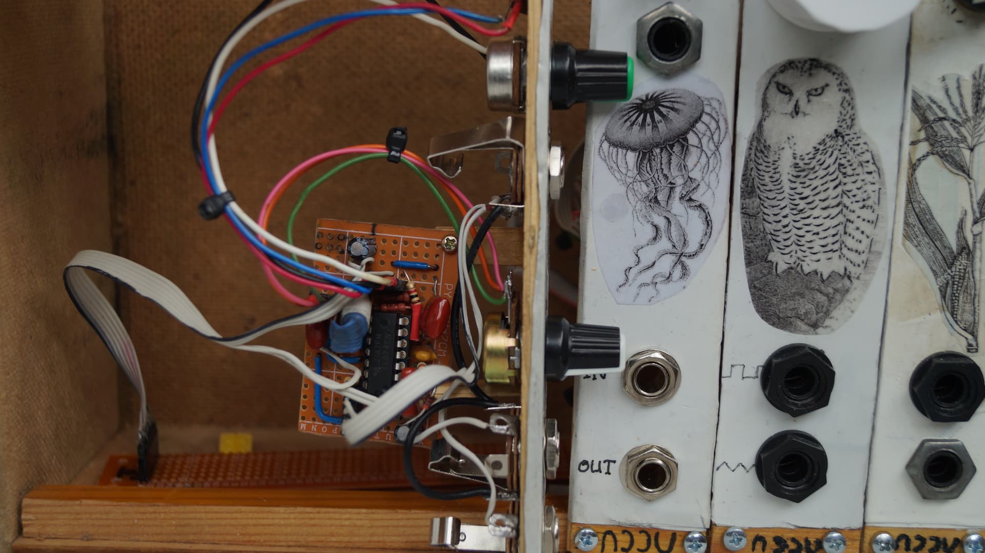
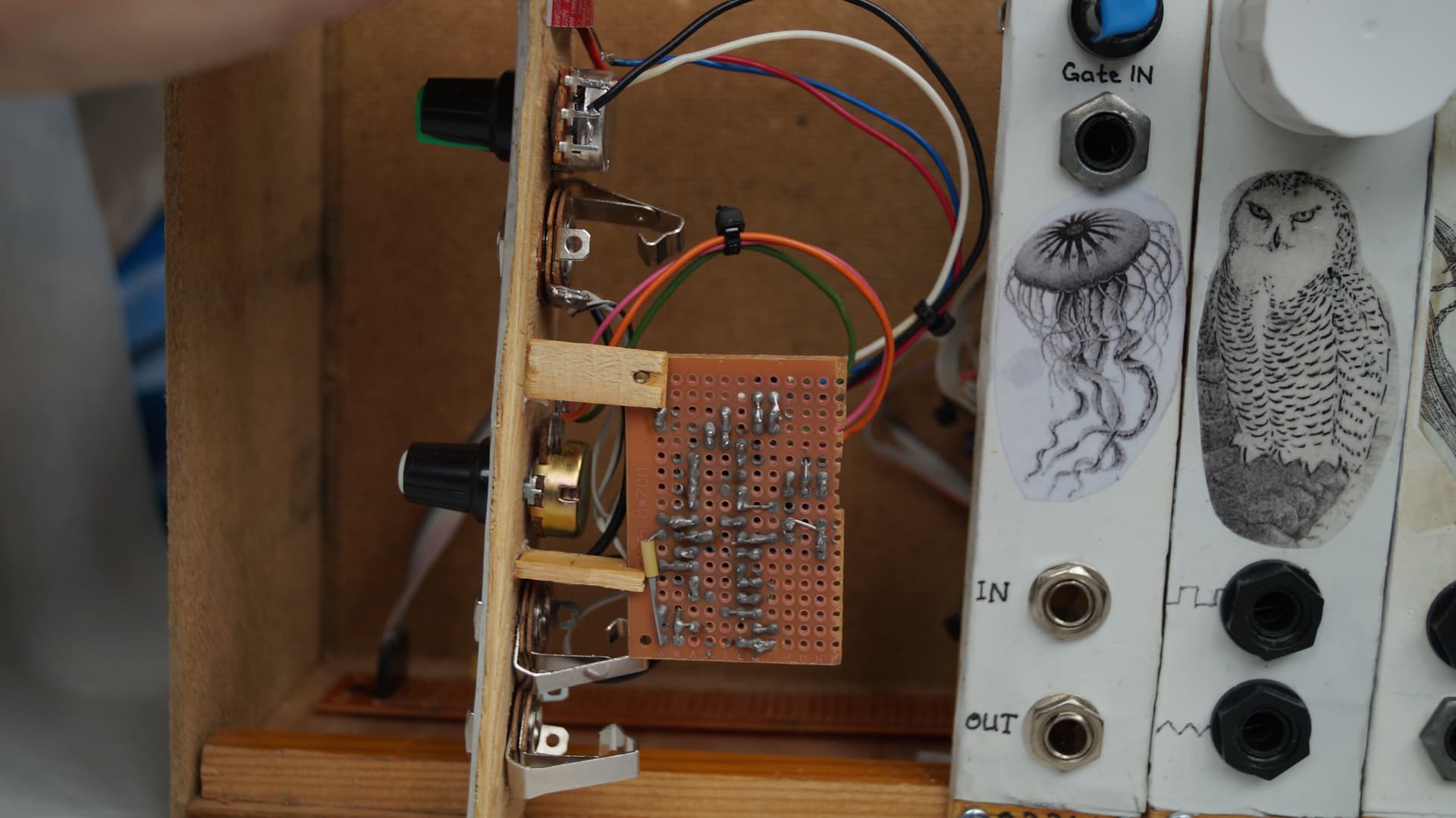
I am very happy with the board… It looks much more neat than my previous projects (and later one too, haha, wait till you see the oscillator board).
As for the front panel, I couldn’t find the name of an artist that made this snail illustration. I found it on some german website with royalty free images (not that I usually care about royalty stuff, when it comes to 15th-19th century engravings and book illustrations, but this time I am not sure if it’s this old). I coloured it a bit with pencils, just to make it a bit different. I need to develop my style and improve my artistic view, hahaha.
Alright, that’s all for now… Ah, no! Wait! I have to show you how i works. I mean, how it blinks
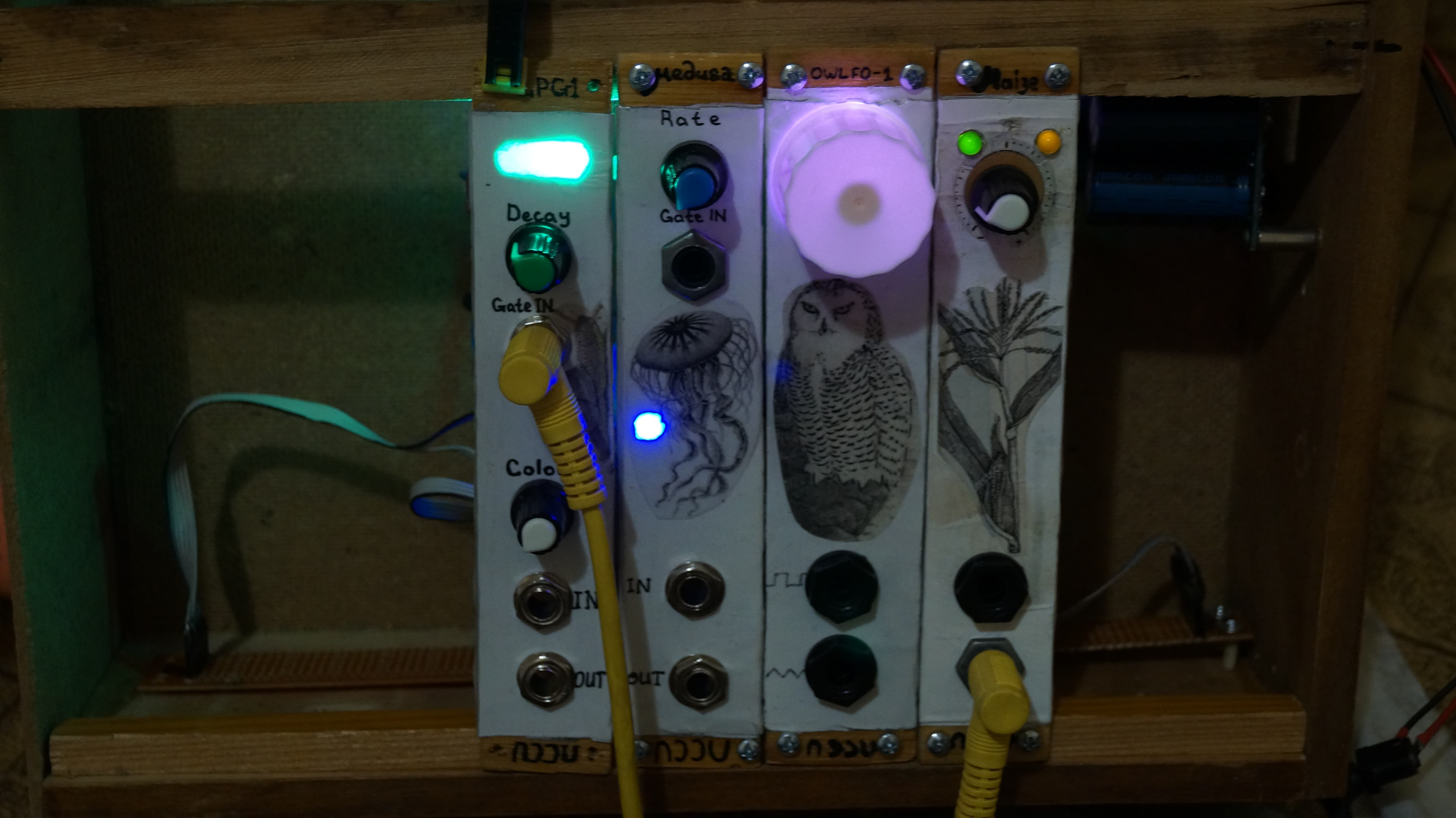
Which reminds me that I forgot to tell you about the window for a LED. Well, I just cut a window and filled it with superglue then sprinkled a bit of baking soda on it. And then I poured some extra superglue on top of it to hide the unevenness (when superglue polymerises it kinda bulges on the middle and leaves the edges superthin, so it creates some kind of lens). It looks… fine, I guess. I could be better, the process isn’t refined yet, hahaha. But I like how it softens the light, disperses it a little.
Next time – the hideous oscillator board! Well, not exactly hideous, more like confusing…
P.S. With all the ramblings I forgot to mention the source of this schematic! It’s ShedSynth’s LPG
3 Likes
Woahh, just catching up on this thread, I’m psyched to see Benjie’s stuff is being talked about! I’ll have to read more closely tomorrow.
Ah, maybe it is such a small world. That’s a nice thought.
Nice work, I do like your creativity in making the LED lense, doing that would not have occurred to me. The only thought I have on the gate, have you checked the levels, I have a keystep pro, and if powered from USB the gate outs can be as low as 4.0v. This may not be the issue, im just guessing.
1 Like
Well, what can I say. I have a lot of stupid ideas! And sometimes they work, haha. It could’ve been better though… I should’ve put superglue in before painting the module. Like pour the whole tube into the window and then file away all the stuff that sticks out. It would look better, I think… Well, next time I know what to do, haha
I think I checked it and showed me something around 10v (I think it was even more than that, around 11v). But even it was like 4v, it’s not a real problem, LPG is triggered by a comparator that is set to 2v or 2,5v, I think (or so it says so on the ShedSynth page, haha). So if the signal is more than 2v, it sends the trigger further and it doesn’t matter if it’s 10v or 3v… If I understand the mechanics correctly…But that’s a nice guess anyway! It was one of the first things I checked too.
Ah, also I checked the envelope output (of my Microbrute) and it works fine with LPG too. It’s all very weird!
1 Like
I’ve been looking at the schematic and your layout above, and I can’t spot any errors, but I do have two ideas. Well it’s more like things I would try if it’s not working
- What are the trigger durations that don’t work compared to those that do, maybe the trigger is too short.
- R1 is shown as 10k, I would be tempted to try 100k, as that is the normal input impedance in Sdiy and eurorack.
I also spotted R8 is shown as 100R, but it looks like you have used 1k, I would expect the output impedance to be 1k, so I would not expect this to be the issue, but could be worth checking.
1 Like
Oh, thanks! You even compared my maze-like PCB layout with a schematic… Wow. I wouldn’t dare, haha.
I will check it later today! I don’t have an oscilloscope, but i’ll try to connect it to my audio interface and check it through VCV. So I’ll screenshot everything and put it here. Later though.
Oh! That’s true. I’ll try to change it. Maybe not today though. Imagine if it fixed everything. Where’s the fun in that? So I’ll start with a scope!
Right! That’s for the consistency. Most of the modules that I saw (and a handful of them that I assembled) were using 100k input impedance/1k output impedance. In this case it’s all divided by 10 for some reason: 10k input impedance and 100R output impedance. I noticed this problem only with the output resistor, to be honest, haha. Again, I was starting to get sick, so that’s my excuse! I think you are right though. 10k on the input could be the reason why it works with one set of things and doesn’t work with the other… And now that you mentioned it, I think it could also be a problem with my LFO, the output impedance of a square wave is basically 50k there. If i am not mistaken, there’s a voltage divider on the output, 100k to 100k. I just blindly copied it from the skull&circuits schematic without even realizing the consequences… maybe I need another LFO, haha. Okay, I’ll measure everything with VCV Oscilloscope later and post it here.
Thanks again for your suggestions and time that you spent checking the schematic!
1 Like
So here’s a problem. The inputs on my audio interface are all AC coupled. So sorry for that! But I decided to do this experiment anyways! It’s pointless though, cause Microbrute outputs Gate, haha. So there’s no problem with length of a trigger… One thing is interesting though and I’ll tell you later what it is!
LFO
DMM shows 10v pp. -5 to +5, everything according to god’s will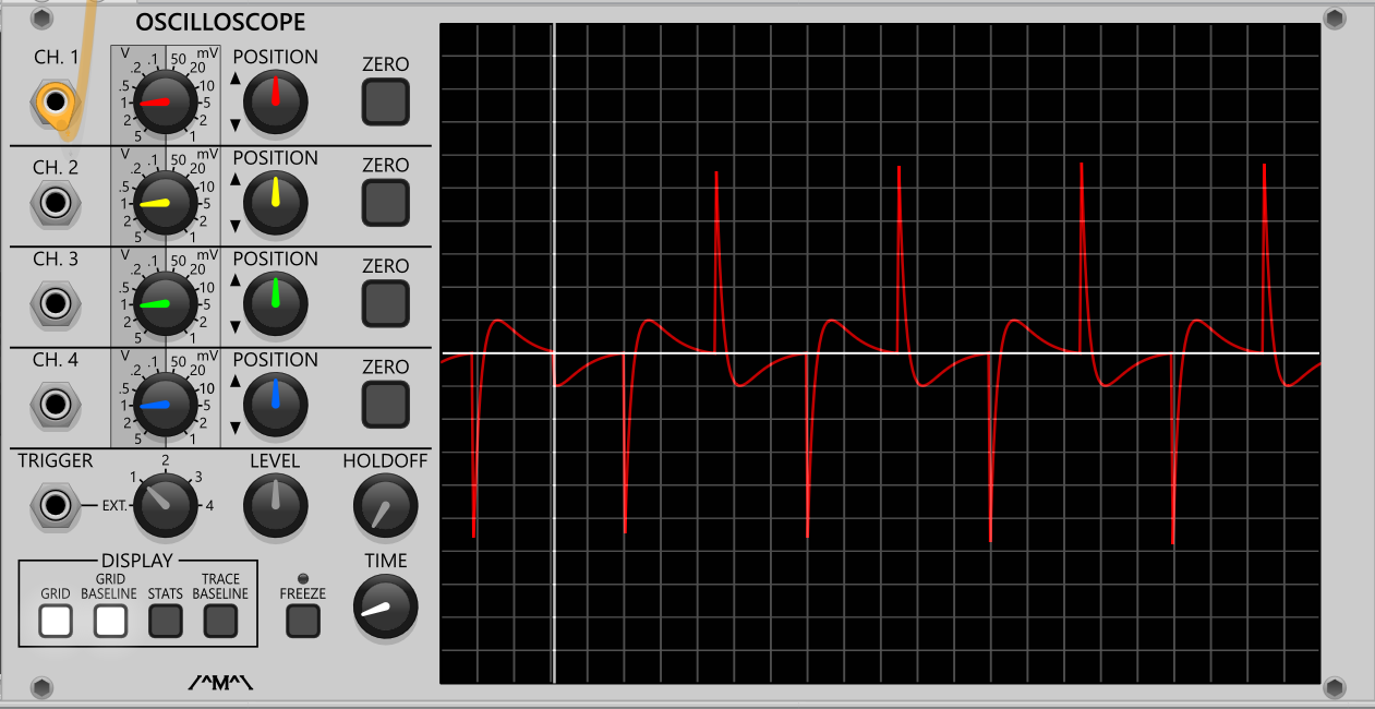
ENV
DMM shows 0-5v with Decay slider all the way up. Again, expected and nice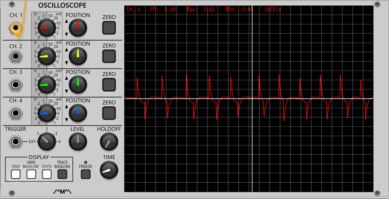
GATE OUT
Now… DMM shows not 10v, not 11v, but almost 12v! Like 11,95v. VCV and my interface attenuates it weirly, to almost 5v pp, but really it is 12v. That’s strange. And that could be the reason why the previous TL074 decided to quit the job. I wonder if when I tame it a bit, it would be usable…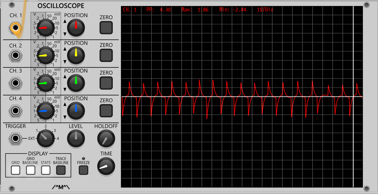
The graphic reminds of an Ernst Haeckel - Wikipedia engraving.
1 Like
One of them actually is! One with a jellyfish
Here’s an original picture (or at least what I took for my project). I can’t find an artist still, but maybe someone of yous like snails
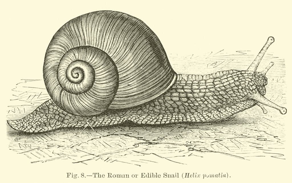
I haven’t found the artist yet.
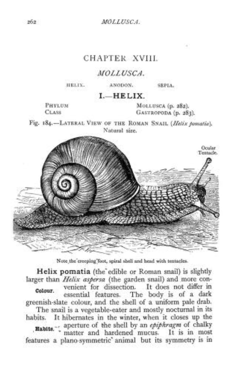
One option is to buy this and see if the illustrator is named.
1 Like
Oh, that’s cool! I wonder why it’s so hard to find the name of an artist though… I mean, I spent maybe two hours when I first found this picture, trying to find a name… But it could be that maybe it was some intern or someone that worked for a publisher… A bit of a sad story! I think this person would be really amused if someone told him or her that in 100 years someone would be looking for their name, haha
Maybe this is the original, I haven’t dug really deep - maybe the book has some attributions - haven’t found them yet.

another scan
1 Like
What a cool website! I love the online libraries that allow anyone to read interesting stuff and see old books and all that!
Would be cool if they had a list of species and illustrations with artists names… But I guess it wasn’t required back then…