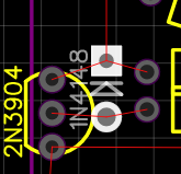
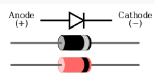
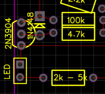
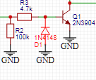
oooh! I see! I think it might be a footprint fault, because in my Easyeda schematic it is placed correctly
While on the PCB page it is reversed!
Thanks! I’ll try to fix it and see if it works now!
Changed this diode. It still doesn’t work. I checked two other diodes. They were placed correctly on the PCB page. It’s very-very strange
Edit: Now it works! I think the diode was at fault. And it didn’t work first time because of the jack sockets… I told yous about it before! And I forgot that I had problems with them… Anyway, now it works! Well, it works as a bitcrusher at least. I have another problem to solve though. I have to make the gate input work. I forgot to tell yous about this problem! Well, new day, new problem… We’ll see what’s wrong with this thing tomorrow, probably… Maybe I just soldered it incorrectly.
Another small note. I misplaced 100k and 1k resistors on the schematic for some reason… It really affected the range and I noticed it right away when the module started working. Fixed it too! Now it works much better.
Okay, so after experimenting with the Gate IN section I think I understand what’s wrong. It attenuates\offsets the signal for some reason, so to overcome this issue a much stronger signal is needed. I am almost sure it shouldn’t behave like that. But again, I am a beginner
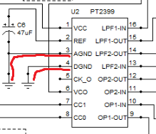
I ordered 5 PT2399 chips to experiment with (I also have an old Mitsubishi digital echo IC that I don’t want to butcher just yet). And I have a question. So with mixed digital\analog stuff you need two ground rails, ideally. Right? But MFOS echo sends them together to the common “ground”:
So my question is - is there something that Ray Wilson thought I must know. Like some obvious thing for everyone experienced with electronics? And he’s like “I’ll draw it like that, but you know what to do!”.
Also I want to experiment with BBD stuff, but I can’t find any chips anywhere here… Maybe I would have to buy a ton of capacitors and shift registers or something like that… Sounds like pain. Does anyone know any good BBD chips that are still in production?
That said, my next module would be an oscillator. And maybe I’ll also make an LPG. I really like LPGs!
A side note - please share your DIY hardware setups! I am really interested in what people use. Maybe it would affect my plan in making modules (for now the roadmap is - OSC → LPG → VCF → VCA → ADSR → SEQ → Clock Divider). I really wanted to make some kind of double oscillator or triple one… Something not fancy, really, but just stuff that provides maximum functionality for minimum effort… But I think my first oscillator would be the MiniOSC by Ben Jiao (which is based on Moritz Klein design that is in turn probably partly based on Rene Schmitz’s 4069 CMOS VCO, which is probably based on something else. It’s cool to trace the connections, even though I am not completely sure that I traced it right).
Looks like you’re having lots of fun, and debugging electronics is fun they say. This is the norm, but a good learning experience. The good thing about building the YASH and the MFOS designs is you know the design works as they have been made a fair few times. You can often find stripboard layouts for most of these designs, If you look on the LMNC forum there is a long long post of verified layouts.
Looking at your list of modules, you may be missing a clock and an LFO, some VCO designs will or can be modified to act as LFO’s as well. You have just built a clock in the YASH, so you have a design, or you could add an output to the one you have.
Your cat looks happier in each new picture, the fur has grown back.
Oh, a picture of mine, I really should write some words about it somewhere, but as you can probably tell I’m not very good at writing. It’s still WIP, some modules are LMNC, a few of my designs, a few by other DIYers, where we have swapped pcb sets, and the bottom row are MFOS designs. My YASH is in the top row.
I seem to have gone full cycle, started writing audio code, then built hardware, and now I am basing my VCV modules on my hardware designs. This hobby is addictive.
Yes! That’s why I am always looking for similar designs and where the stuff came from… I don’t easily trust any given schematic, hahahaha
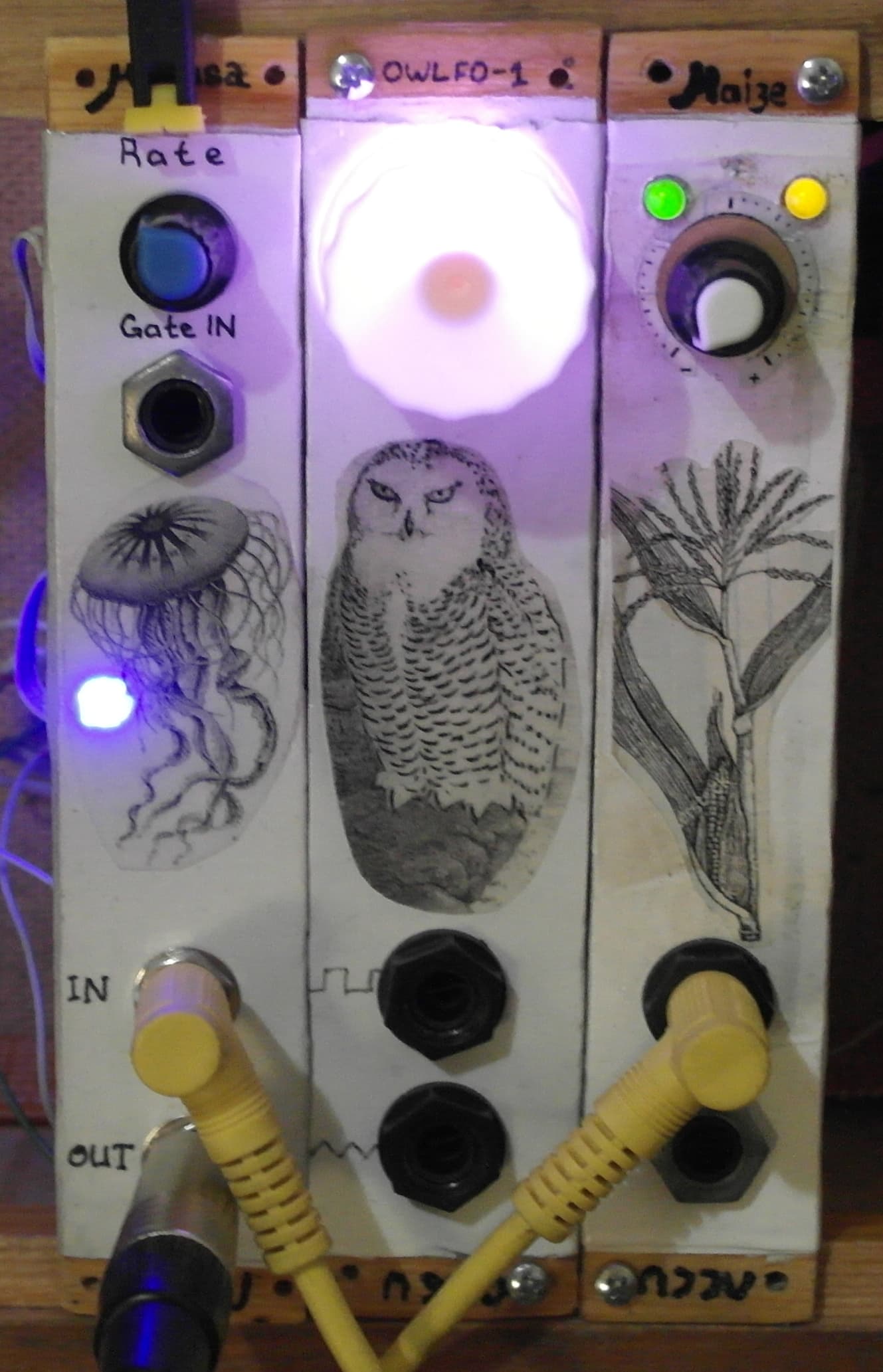
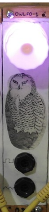
I do have LFO, it’s the OWLFO that I built earlier.
A very simple one, but it works… And it also works as a clock. I was thinking about making a 555 clock with clock dividers outputs on the same board, I saw this design somewhere… Maybe I’ll do that!
Yeah, but they don’t sell stripboards here… And I really like freedom that simple perforated boards gives me. It’s a pain to solder long tin bridges sometimes, but I think I am doing fine with that!
I can see that, haha. Well, I mean the visual similarity. But probably the functionality too! Anyway! Cool rack! I see the reverb module, is it a spring reverb or something based on echo chips? I like reverb! Though I have an old Alesis Midiverb, so it’s not like I am in a desperate need of reverbs, haha. But it would be interesting to know what kind of design it is!
I would advise against any 555’s in a synth, They put a lot of noise on the ground rail that you will be plagued by. Reminds me, you were asking about analog and digital grounds, I just keep them separated until the power connector of the board, but there may be better ways.
Thank you! Noted! What about 7555 though? Is it any better regarding the noise?
Also after looking at you setup I realized I need mixers, hahaha. It’s a bit too early though, cause I don’t have anything to mix… But I should add it to my roadmap!
Yeah, that’s probably what Ray Wilson did too… But I am thinking there must be a better way to separate them
I have a couple of reverbs, A spring tank, the silver thing on the outside right of the box, it’s just a box similar to a guitar amp. The ones in the top case are my attempts at making a programmable module using pi pico microcontroller, I have made a few different modules with this design, but it needs more work as it can be very noisy, the reverb code is very simple but can give some weird longer tails. Oh, I gave up trying to make microcontroller modules, for me analog is more fun in hardware, and dsp is more fun on a pc writing rack plugins
Oh, I see now! I haven’t noticed it before… It’s nicely hidden! Well, not hidden, but kinda unnoticeable, at least on the photo. Looks nice, very natural!
Ahhh, I see! I don’t like programmable stuff too… Not like it’s cheating, more like… I don’t know. Maybe impure, hahahaha
I have never used one, you could try, you dont tend to see them used in synths, but that could just be because we are afraid to try. Even if the clock is noisy, you could still use the divider. For me the fun when the building was learning from my mistakes, I rebuilt many of my models after gaining more experience.
re pt2399, I have ordered pcbs to make some of Benjiejao’s mini-delay’s - I’m not sure you were looking, but here’s his pages on it.
Re BBD’s I want to make soething with those too - I got some “Coolaudio V3205D V3205 BBD 4096-STAGE” from an ebay seller - I think cooladuio is the only company making new BBD’s is CoolAudio.
I also have a few other BBD’s i picked up from other ebay sellers - But i haven’t check them yet. The rumor is that there are many fakes.
Oh, I like it! I haven’t seen it, even though I was checking Ben Jiao’s page just today… Thanks!
I heard that too… Hope yours are fine!
Oh, that’s nice! I was checking BBDs in my local internet store. They don’t sell it here… Even the specialized shops don’t sell them now. But I see, maybe I have to check Alibaba or something!
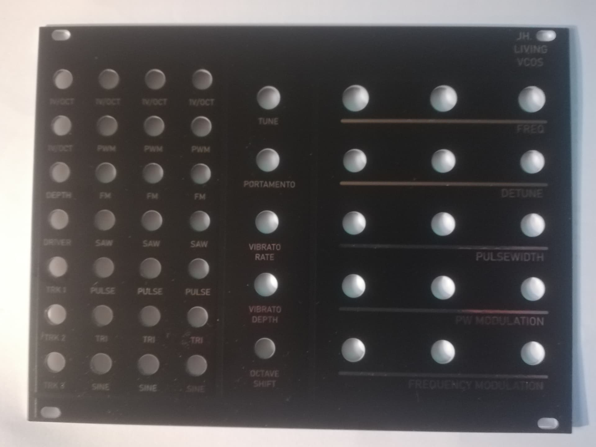
I’m building “Living VCO” design by Jurgen Haible as a first DIY oscillator, following some modwiggler schematics+ gerbers (by barcode).
The decision was not an easy one, but it’s supposed to have “untamed bass range power of early EMS and Moog VCOs … tracking a keyboard voltage over 5 or more octaves”
I ordered pcb’s for 5 drivers with each 3 oscillators.
I’m still building.
I think it’s gonna sound fat into “Valvs” tube VCA’s with former USSR low voltage tubes.
Oh, it looks cool! I would go crazy though if I try to build it, haha. It looks complicated! I mean, I usually build everything on a perforated board, one sided. But that’s cool that they sell PCBs! Definitely show us how it sounds!
Nice! Looks very cool and I bet sounds even cooler! I have some old USSR vacuum tubes, not sure if they are usable though… I think they were meant for TVs and stuff. But I could be wrong. Maybe I’ll try to check them and if I am lucky, I’ll check the schematic for it! I like tubes.
Thanks! Sadly It’s useless to me, cause I live in Russia (nobody ships stuff here now), but maybe other people would find it useful!
 While on the PCB page it is reversed!