DIY Module Front panels (two questions and a big tangent)

You have been making progress since I last checked in on this post. lots of it, oh and I see your cat is looking happier, and has a new friend.

Cases, they are always too big and too small at the same time, I think mine were 150mm deep, but that is a lot. The good thing about making the first case is you learn how to make a better second one.

I see you mention sources of random, a very diy way to reverse bias a semiconductor, normally a transistor, you have probably already seen this before, but here is the schematic from my noise module, the top section labeled "White noise generator| ", you may need to experiment a bit to make it meet your needs,.

I never did make a decent mixer, just a mono one, every time I sat down to work out what I wanted the design got out of hand, so I use used a few mono ones.

Thats a cool demo video, I still like the Led in the toothpaste lid, its a really nice touch. Thats the good thing about Diy, you can really make it your own.

1 Like

Haha, yes. We don’t know if it’s a friend though… I think he doesn’t trust this cat…

Oh wow. That is a very deep case. It’s twice as deep as mine and I thought that mine is maybe too deep, haha. But I am planning to make another case, as I said earlier, and this one would be even deeper… Not that I wanted it to be this deep. I just found a chipboard that I don’t need and I saw it. sew it? Hahahaha. Well, i took my saw and i cut it in the middle and it’s still too wide. I’ll show it when this project would be finished. It’s as wide as a bookshelf. You can keep your favourite books collection on top of your modular! That’s really cool!

Thanks for the link! I’ll look into other modules as well, if there are other modules, haha, and maybe I’ll steal something, haha. Yeah, I know about the semiconductor noise. I wanted to make a diode one too. I have a white noise module that uses the old soviet transistor to make noise… But now I want to check what a diode would do. Anyway, yeah I know about noise. But I am not sure how to use it. Like say a Turing machine module (that is open source and I definitely want to build one, but not now again) uses a transistor noise. And what it does is actually pretty close to what I was thinking about when I was interested in analogue Bernoulli Gates. I actually some time ago recreated a Turing Machine module in VCV, using a gate source, bernoulli gates, shift register and DAC. It works just fine! Let me see if I can find it…

Here it is! So back to the physical stuff: what I need is to just take the noise source and all the stuff that creates gates and triggers for DAC in the Turing Machine module and to somehow attach the potentiometer to control the randomness of the gates. And I think it would be easy (see me realizing that it’s not easy at all in few months). But I want to understand what it actually does, haha. And I mean in details… Like to really understand it so I could maybe modify it even further… We’ll see!

I mean stereo mixer isn’t really necessary, but I like the stereo stuff! Maybe if I was into 5.1, I would do the 5.1 mixer, haha. I can’t even imagine how to make one… But I am sure there are schematics on the web, haha

I like it too! Had to redo something though. The inner thing cracked for some reason. I mean the pen cap thingy cracked. So I had to glue a piece of rubber isolation on top of this pen thingy. So it wouldn’t crack further and hold the potentiometer shaft better. Sorry if my explanation is confusing, haha

1 Like

A little update. I haven’t done the boards, cause I still need to buy something (new tip for my soldering iron and maybe I’ll try the rosin core solder). So I decided to start with the front panels again. I made four of them. All in different styles, as you see:

The first one will be a mixer. Big chinese character says “Gu”, I downloaded this picture from wikipedia, haha, cause I would never even try to copy xiaozhuan. The big red one is also “Gu”, but this one I can write no problem (a bit sloppy though), cause it’s kaishu. And so I did! I could’ve practice more to make it as pretty as possible, but I am impatient. Gu is a chinese poison magic thing. It’s very interesting chinese alchemy stuff. I don’t know much about chinese alchemy, sadly, but this one and the pill of immortality I am familiar with. It’s all taoist, predictably.

The second one is a double VCA module that I took from Hagiwo’s page. Maybe that’s why I unconsciously decided to use a japanese woodcut gravure. It is a very sad frog, yes… The artist is Matsumoto Hoji. He has a lot of cute frog pictures. I took this one, because it fits nicely. There was a problem with the text - that’s why paint job looks ugly and there’s no text for some of the inputs\pots (there’s no pots and inputs\outputs yet, but you know what I mean). I will add it later. Paint isn’t completely dry yet

Next one is a double mult. Picture is very generic alchemy\astrology sign or whatever they call it. I wanted to use some kind of the Moon picture, but I liked this one more. Moon is symbolic, it wouldn’t shine if there were no Sun around. I wanted to show you that I am not stupid before we go to the next module

ADSR. Rene’s fastest envelope. And there are lots of cats on the face plates… I don’t know why I did it. I wanted to and there was nobody that could’ve stopped me, haha. Anyway, I like it. It looks daft, but I think it breaks the overall pseudo intellectual feel that you might get when looking at my modular… All these alchemy and old naturalist book pictures. And suddenly you see a module with poorly drawn cats! “Oh! I see” - you might think. - “He’s not actually pretentious. He’s stupid!”. Sorry for my russian punctuation.

Well, as you see, things are moving. Slowly but surely!

1 Like

Well, things are moving indeed. But not in the direction I really enjoy… It seems like few days ago while testing the new module (double mult) I burnt few of my modules. Well, they do work, but not like I would want them to work… The unlucky ones are:

  1. OWLFO-1. I think I destroyed one of the capacitors or transistors… Not sure. The symptoms: the light blinks few times and then goes constantly on. Square output doesn’t work. Triangle output does work, but if you lower the rate, it goes to -12 and stays there until you move the rate knob again, then if the rate is higher, it kickstarts and goes ~8v pp. Maybe it’s actually 10v, which is ideal. But I am measuring it with my DMM, and it’s not exactly precise… I took the board off and changed the op amp IC. I also connected it to my double 9v battery PSU. Nothing helped. So I decided to wash it with a soap water (it’s not ideal, of coarse, but it seems like my old flux should be removed this way and not with isopropanol. I washed it with isopropanol later too). I don’t expect it to work after that though, so I will also desolder some of the capacitors and transistors. My goal is to make this module an example for other modules. They should be scared. I dismembered their brother. I would be scared for sure.

  2. Medusa (Yash). It also has similar problems. It blinks but range of the inner oscillator is very short and it starts around 12 o’clock position, so everything lower gives the same frequency. I know what you are thinking! Well, probably. You think that there should be a problem with the negative power line. And I was thinking the same thing! But sadly, no. Clock in Yash and Rate in LFO is +12v to ground. So There should be some interesting trouble with a capacitor or a transistor… Not sure yet. And I haven’t tested the Sample and Hold function of Yash at all. So it could be that LF398 chip is also fucked… I hope not! Would be a big trouble to get a new one.

  3. OSC. Yes… See the pattern? Is it everything that has to do with oscillation? Nooope. It’s everything that “stays on” even without anything connected to it. Because my noise module was also a victim of this strange electronic plague. So OSC symptoms are similar to LFO ones: when you lower the rate\freq knob it goes to -12 and stays there. Also the outputs got messed up: PWM knob for some reason now affects the saw output. Which is cool and all, but that wasn’t a feature before. I think, again, the problem should be with a capacitor or a transistor. When I check the OWLFO circuit and find the culprit, I hope that it would be something that I can translate to other circuits… Otherwise I would have to desolder everything in each module, which is a huge pain.

  4. Alright, Noise module is the last one in this sad list. It outputs noise for 5 seconds or so and then goes mute. And the LEDs turn off too. Well, one gets dimmer, one gets off. So It seems to me that this one definitely has a capacitor problem.

The alternative theory is that it is actually a PSU or power line problem and there’s something with the ground line. So it doesn’t allow the modules to discharge their capacitors effectively. I don’t think it is really the case, cause if you connect these modules to the 9v PSU, they still act exactly like this anyway. But I think I will check the PSU just in case. And I also ordered a bunch of new 7812\7912 voltage regulators and I will probably make another PSU later for my other case (I haven’t started working on it yet) and I also have to think hard how to modify my power connectors so there wouldn’t be anything like that ever again. Ah! So – what I think happened is I connected the power for the new module wrong way round or I missed the pin, misaligned the connectors… I don’t really know. I panicked and forgot to check what I did wrong.

Anyway, nothing can stop me now, as mr Reznor likes to say. It is sad to maybe lose few modules because of this, but I have a ton of them planned, so it’s not critical at all. I’d just have to be more careful from now. And also I don’t think the affected modules are unrepairable. It’s probably one or two electrolyte capacitors (maybe also a diode or two - everything polarized could be a suspect). Worst case - all the capacitors, diodes and a couple of transistors. So, like… 5-7 components. It’s not a huge problem, just a little annoying

Not to beat a dead horse, but your symptoms are in alignment with expected behavior if you use an acid flux solder rather than rosin core.Things just stop working after a time.

1 Like

Sorry to hear this. Commiserations. I’ve only ended up with a smoking module on one occasion, but it didn’t take out anything else with it (tested it in an empty pod). Diode the wrong way around with mine.

1 Like

That could be too… But VCO is affected too even though with this one I think I used the rosin based flux… I am pretty sure! Anyway, I will not use the iron chloride stuff again, hahaha. I actually bought 500ml of rosin solution yesterday! So I am set for a long time now with the normal flux. But I think I need to wash everything I did before with soapy water, cause apparently that’s the only way to get rid of the old acid or iron chloride stuff… Yeah… The more you know! Thanks for your advice earlier! I ordered a pack of rosin-core solder too!

P.S. Oh, I actually used the bad flux on my VCO. I remember now. I destroyed a bunch of 40106 ICs because of that. So maybe you are actually right! Huge pain to reflow everything with good flux though… And I don’t even know if it would help or not…

1 Like

You got lucky! Or smart actually, in your case… I got lucky few times when testing modules previously and connecting them wrong way round. It was okay… But maybe it is connected to the flux I used… Maybe it got activated by the current… Like an electrolytic reaction or something…

1 Like

UPDATE:

It looks like @k-chaffin was right. After washing and washing and washing then reflowing then washing and washing and washing… LFO works again. Or so it seems. So it encouraged me to wash the Noise module too. And I was really surprised just how much of this stuff, the old flux, stuck to the board and components. In water it started to oxidize, I think, and it created a thin coating on almost everything… And when I think about it now, it really was expected, I did it myself when washing the board with isopropanol 10 times or so. I wasn’t aware of the fact that it could be washed with water only. Or maybe like 5 litres of isopropanol. So I was actually actively spreading the affected area. It looked disgusting. Some kind of thin white opaque layer on everything. And It took me 5 minutes of washing it with toothbrush and soap and then isopropanol and soap again. And even now I am not sure if I got rid of this stuff. When I think that that’s what I should do with almost every module, I get… annoyed at myself. Well, whatever. It happens.

So my new theory about what went wrong: weather! It has been raining for a couple of days and seeing how the white disgusting oxide coating appeared after pouring some water on the board, I suddenly realized that it could be what actually happened! But it was moisture in the air. And it wasn’t this apparent. Just a bit of oxides here and there. Well, it is a theory. I am also not sure if the affected modules would work for a long time. Cause I haven’t re-soldered the joints, I just reflowed… reflew? What? I did the reflowing, haha. With the healthy flux this time. Maybe I just have to admit that I need to redo the modules… Which is not this hard, actually. Well, you know it. There are no particularly rare components (aside from LF398, which is hard to find in my city, but I can order it from Ali and I will. Meanwhile I could just use the old LF398) and I also have a visual reference, which is an old module, so the whole work would be to just put the components the way they were on the old board and solder everything together. Easy as pie! So maybe I would have to do it. I don’t want to, but maybe I will.

That’s all for now! I will write what happened to noise module after reflowing, that would be maybe in two days. Have to work…

Angry cat:

3 Likes

It would take a brave person to stroke that angry cat.

Sorry to hear about your troubles, Diy synths are all about learning from previous miss haps, and it can be emotionally challenging when you discover an earlier decision is not ideal, however, I find it rewarding when the issue is identified and fixed.

While I never had the solder issue you seem to be suffering, I have also made the mistake of plugging in a whole row of modules with a reversed power supply, leaving many of the modules not functioning completely. I was lucky as I had only built a few modules, and as expected for my first modules, they were not the. best. This was the point I decided not to try and save money on power connectors, and just to use the same connectors as eurorack. While it is possible to force the connectors, it does give a layer of protection.

I also have diodes on the power rails of each module I build, but this is only done by a few module developers, so there may be a reason I am not aware of as to why this may be a bad idea,

Hopefully after this setback, you will have a much more reliable rig in the future.

1 Like

Yes… I mean all of my modules are me first ones for now, but the very first, the noise module is the most unprotected. It doesn’t even have the bypass capacitors on TL072 and… At all. But now I actually have a template on EasyEda. It looks like this:

image

It says 1uf, but sometimes I use 10uf. I am not sure if it affects things at all and If I need them in every module (like in mult, this one is actually from my 2xMult schematic, which is a new module that I’ll show later), but I just like these small caps, they look cute. It is a fairly recent innovation, before that (starting from LFO, the second module) I had this template:

image

And again, it was everywhere. Sometimes I want to add diodes there, but I am too lazy to mess with my old modules layout. It’s not this simple, sadly. It would be easier to redo it from scratch.

I was considering top do it too. But I don’t know how they call them. And I already kinda spent lots of money on things on Ali, that I should get in few weeks, the most closest package should arrive in two days, maybe three… It has DACs and LEDs and some other stuff for Arduino projects (quantizers and such), so I am actually thinking about DIY way of restricting the power connectors. Like maybe I should glue something on the connectors. The other idea is to clue something on these connectors and make the connectors symmetrical. Like +12 -12 gnd gnd -12 +12. But I like 4 GND wires. And I would have to redo the wiring of my old modules if I want to do that… And I have to redo the PSU connector too… Too much trouble! I need a mechanical solution, I think. Like What they do with Eurorack power connectors. Some kind of notches and all that. I am thinking hard how to do that in my low effort DIY way. I have to do it sooner, cause for now the case for my modular is empty and I have an opportunity to fix my power line and connectors troubles. I had a very sketchy power line, the power distribution thing, btw. It had naked wires on the bottom, so I am redoing it right now too. I also ordered a bunch of striped boards for the power distribution lines in my other case (which again isn’t ready yet. At all, it’s just planks and screws for now). Yeah… I’ll show you later what the problem was with my old power terminals or whatever they call it.

I don’t think it is a bad idea… Maybe people don’t use it because they don’t usually have a problem of connecting modules the wrong way. Well, it also could be some kind of power consumption thing. Like it eats the current. So you just waste it on something that is fairly unlikely when you have proper connectors. Maybe probably.

I hope so too! And It looks like it will be a nice rig. The power distribution would be much more reliable and there would be no weird flux… Or at least not as much as there was before. That remind me that I also need to wash the potentiometers and jack sockets… Argh.

So I’ll write an update on the whole situation later today or maybe tomorrow. Spoiler - washing and reflowing helped a lot

1 Like

Alright.

So almost everything is fixed! Noise module works, LFO works, YASH works. I also washed and fixed stuff that wasn’t a problem, just in case: I renewed soldering for LPG and added some proper wiring for power distribution boards. One thing that is still buggy is VCO. I think I disconnected something when reflowing or maybe I shorted something, I am not sure. I have to check. That’s also the most… complicated schematic, I guess, in my collection. It’s not really complicated if you compare it to something professional, but to me it is. It just has lots of components and it’s not really difficult to assemble, but it is a pain to check what’s wrong… Anyway, I’ll do it later.

Meanwhile I killed my first TL074. Like completely killed. Before that I just destroyed one of the op amps in the package, but this time I burnt it well, Cool blue smoke and all. It was an IC that I used in my Cornucopia clone. The very first module! And being the very first, it has no protection at all. No diodes, no bypass caps, no nothing. I think I already told that in my previous post and that’s why I mentioned it there. Anyway, I attached the power connector the wrong way (I never learn) and yeah, It popped. It was cool! And the smell was nostalgic somehow. I remember destroying electronics when I was a kid. It had this cool smell, not pleasant, but cool. It’s like cigarettes – not pleasant, but interesting. So yeah, another IC in my “Deid” box.

So my plan for now: wash VCO again. Cause it still has this white residue in some places… I shall take a photo! I’ll show yous what it looks like

the white stuff on the wooden thing is actually superglue. Look at the board, haha

Sorry for my soldering. It feels like I am showing you what I usually try to hide, haha. But no secrets here! Look. So that’s what’s left after a proper washing… Imagine how it looked before! It was disgusting. It is a bit gross now, but before washing it looked like… i don’t even know. Like I found it in the bin. I don’t want to rewash everything, cause it’s troublesome and I don’t even know how to wash it so there would be no weird flux left, but I will rewash VCO, as I said earlier. I’ll try to wash it very hard. We’ll see if it would come off. I hope so. But I don’t think it would fix my troubles with this VCO. WHich is, by the way: PWM doesn’t work. Or it does, but it affects the pitch in one step. When you dial it, the sound get’s like one tone higher and then it does nothing. FM amount lowers the pitch for some reason. So you can find the sweet spot where they counteract each other. But otherwise it works fine. It gives a clean sound. Or maybe not completely clean, but it’s cleaner than it was before the wash. So I have to check it. Yeah… And I just suddenly found a problem. Five seconds ago. I disconnected the solder bridge that solder people worked really hard to build. I’m sorry! Well, I hope that would fix everything. But before that I really need to wash it again. And I thought that 10 minutes with soap and isopropanol would finally wash this stuff off… Meh

1 Like

Well, as you see, cat says that everything is okay. I fixed PWM on my VCO, it works. I feel like it is more wobbly than it was before. Maybe it’s because of all these water and isopropanol baths… I probably need to renew the thermal paste on the exp converter transistors… What’s my excuse? I’m lazy.

So here’s what my power distribution lines look like now

And here’s what it was before (re-enactment)

----And here’s my new trouble!----

So I am planning to build XR2206 VCO, as I said before. I have XR2206 and I have LF something something op amp that Thomas Henry recommended. I have a pair of reasonably matched transistors. Everything is ready to be built! Or is it? No…

image

What the hell is this? Is it NTC or PTC? Probably PTC, maybe not though… But when I started looking for it on Ali the whole “ppm” thing got me confused. So I googled and googled and now I kinda understand what it is, but I can’t find it on AliEx, which is my only option. So here’s a question for wise people: should I just use whatever PTC (or NTC if it’s not PTC) or should I cheat somehow? Or maybe should I just forget about this schematic until there would be a way to order it from thonk or whatever? I am not sure if it would happen soon though…

I am also having a bit of a trouble with chinese microcontrollers. Out of three LGT8F328P boards I ordered two use some kind of weird USB to UART bridges (ch9340). And I can’t install drivers for this thing on my Windows 7. Boards are fine though. They blink and seem to be work nicely. But I can’t connect to them. So I ordered a programmer or whatever they call it. I also got my Mh-Tiny88, which I ordered by mistake. It works fine too! I think I will use it for a clock module. So I will have one more better board to play with. I am thinking about an oscilloscope module… That would be fun!

So my question is: what should I do with the tempco thing? This is the only thing that is stops me from planning the XR-VCO. I have lots of stuff planned, but I really wanted to make this one too! It has linear fm and all the cool stuff. But I am afraid that if I just replace PTC (or NTC) with a resistor or just random thermistor, it would be wobbly as hell. And maybe it would be impossible to tune it properly

That’s all for now! Next time - two new modules!

Thonk sells some:

https://www.thonk.co.uk/shop/2k-tempco-3500ppm/

I have used platinum smd resistors in my J.Haible living VCO’s - samples from vishay. It’s allmost the same temp coefficient. (+3850ppm (0-100 dec C))

You can even build without tempco - but re-tune as it heats up.

more to read: Synth schematics--::--Exponential Convertors

1 Like

Well, I can’t buy from thonk and other places, because Russia… I was considering doing it without tempco at all… Or maybe replacing it with a multiturn trimmer with an easy access. Like putting it on a faceplate or something… But I am not desperate yet! What about these platinum smd resistors? DO they sell it on AliExpress? Hahaha. Maybe I should solder some leads to them and use it as through-hole…

Anyway, did you finish the Living VCO? I remember it was like a million of components there…

I built a nice little scope with a stm32f103C8T6 (same as “blue” pill)

The screen is small - perhaps a DSO138 (from aliexpress and others) is a better buy.

The original :

I made a pcb to use some components I had - I didn’t use the “blue pill” board, but soldered the MCU to the pcb. The kicad files are not ready to share to the public (somebug regarding the PWM output i haven’t figured out yet).

edit: anyway, here’s my kicad files, and the gerbers in the prodocution dir.

https://hidrive.ionos.com/lnk/ulTCPulL#file It’s what I’m running, but there’s no 1000Hz out on the PWM - and there’s something wrong with the scaling of CH2 in one of the ranges. (I haven’t gotten around to fixing the code yet).

2 Likes

Oh! I actually ordered a blue pill! I ordered few different microcontrollers… Even a very sketchy Seeeduino Xiao, which I haven’t received yet, but I have doubts already. I don’t think it would be a good one…

Yes, I was thinking about it too. But the modular design is much more preferred, I think. Like you can buy another display and reprogram stm32 if needed - and now you have a bigger screen. Maybe you can do that with DSO too… But I don’t know. I like things that can be disassembled and used for different projects, I guess…

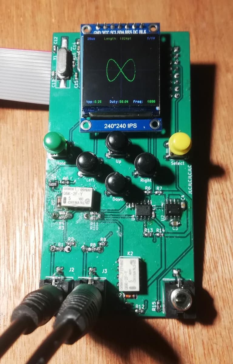
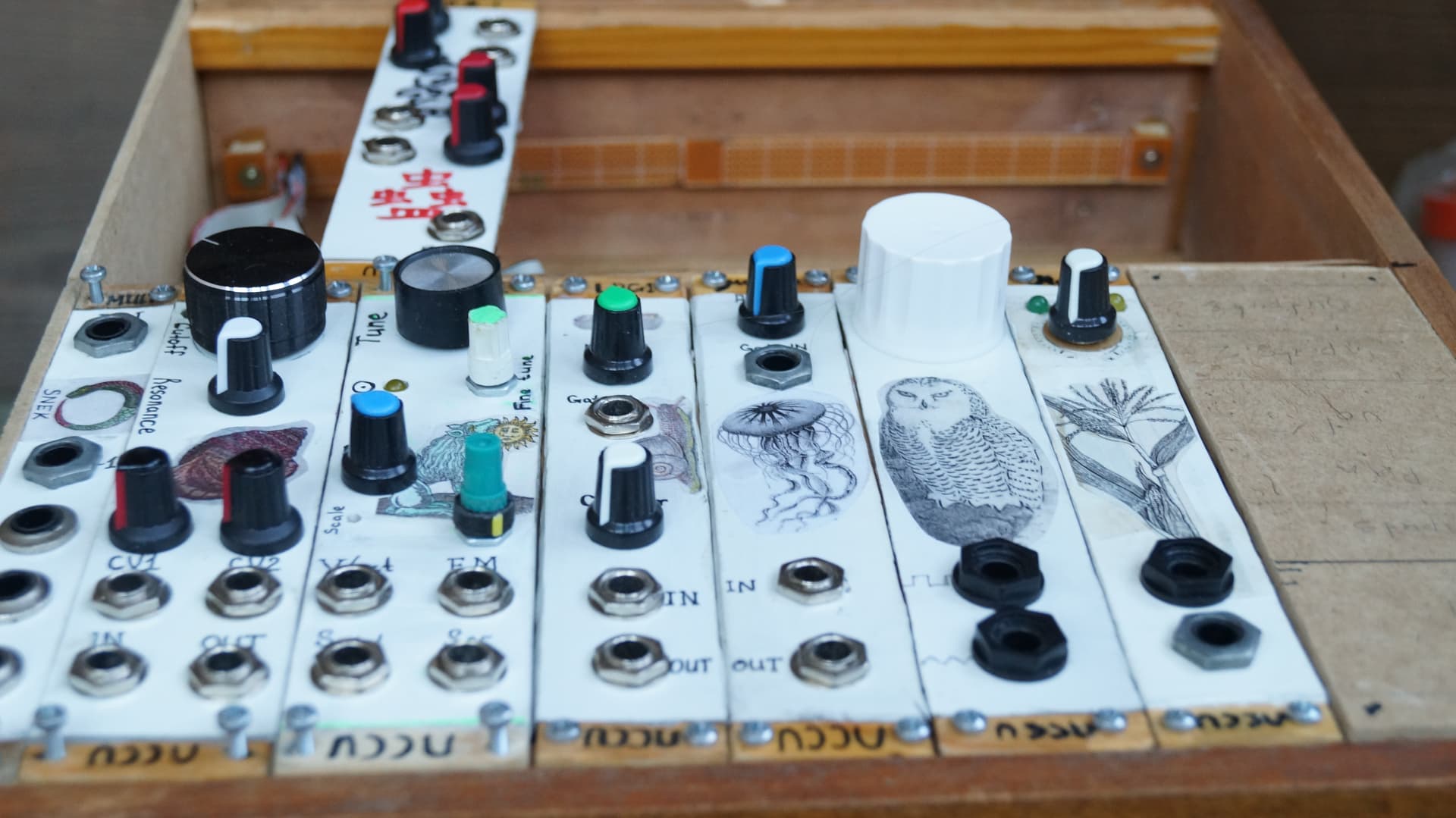
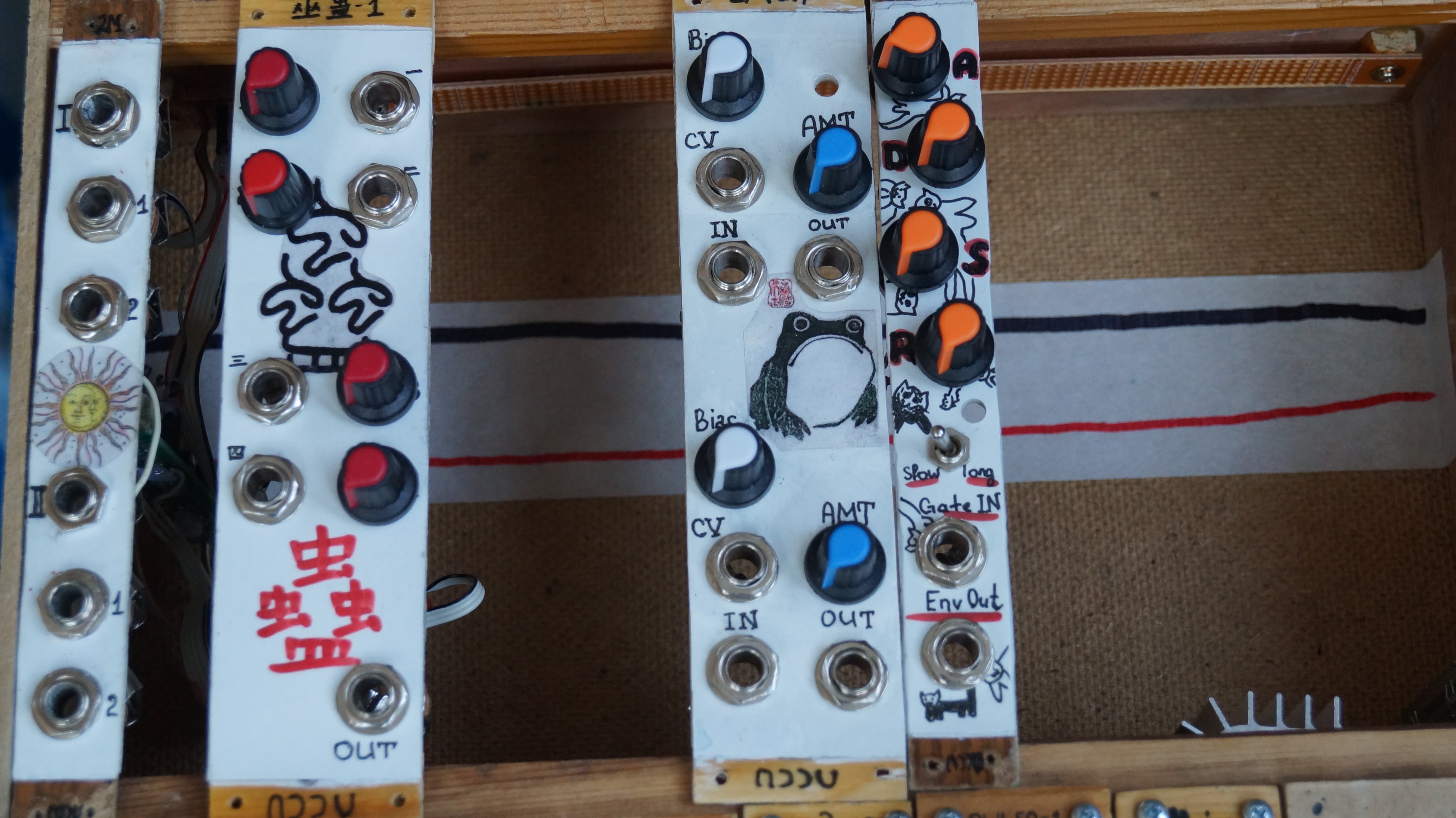
First up, two new modules, as promised!

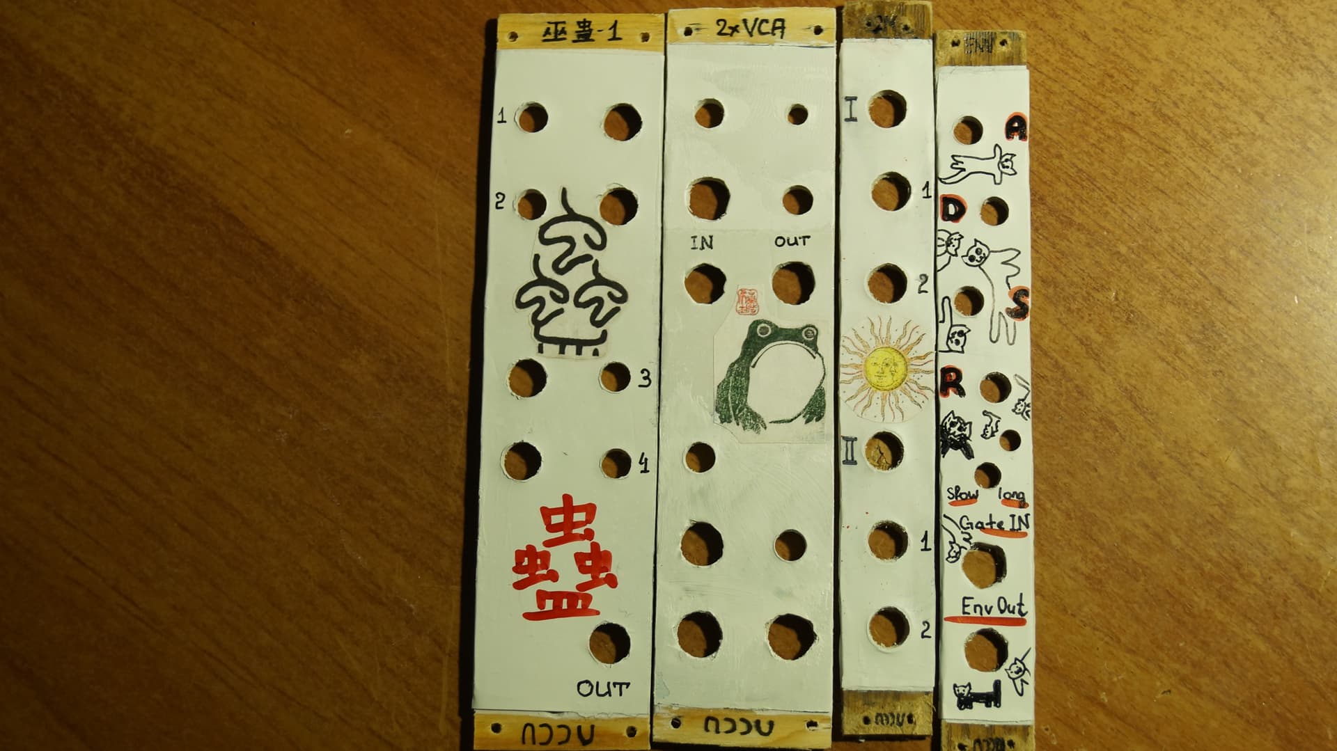
This one is a mixer. Based on NLC 4hp mix. It’s right in the middle, between LFO and VCO. It is a DC mixer, but I am using it for audio, because I am this kind of person. As I said a week or so ago it’s called “Gu”, not only because I am pretentious, but also because I wanted to have some kind of linguistic diversity in my rig. I know a little bit of chinese, not enough to read and speak freely, but I like it! It’s a very cool language. It sounds cool and written language looks cool… All these characters. It’s sexy! That’s how I see it. Ethiopian, arabic and mongolian also look cool, but these ones I don’t know at all. The only thing I know is that “Cat” in mongolian is “Muur” or something like that. Very cool!

The other module is 2x2 mult.

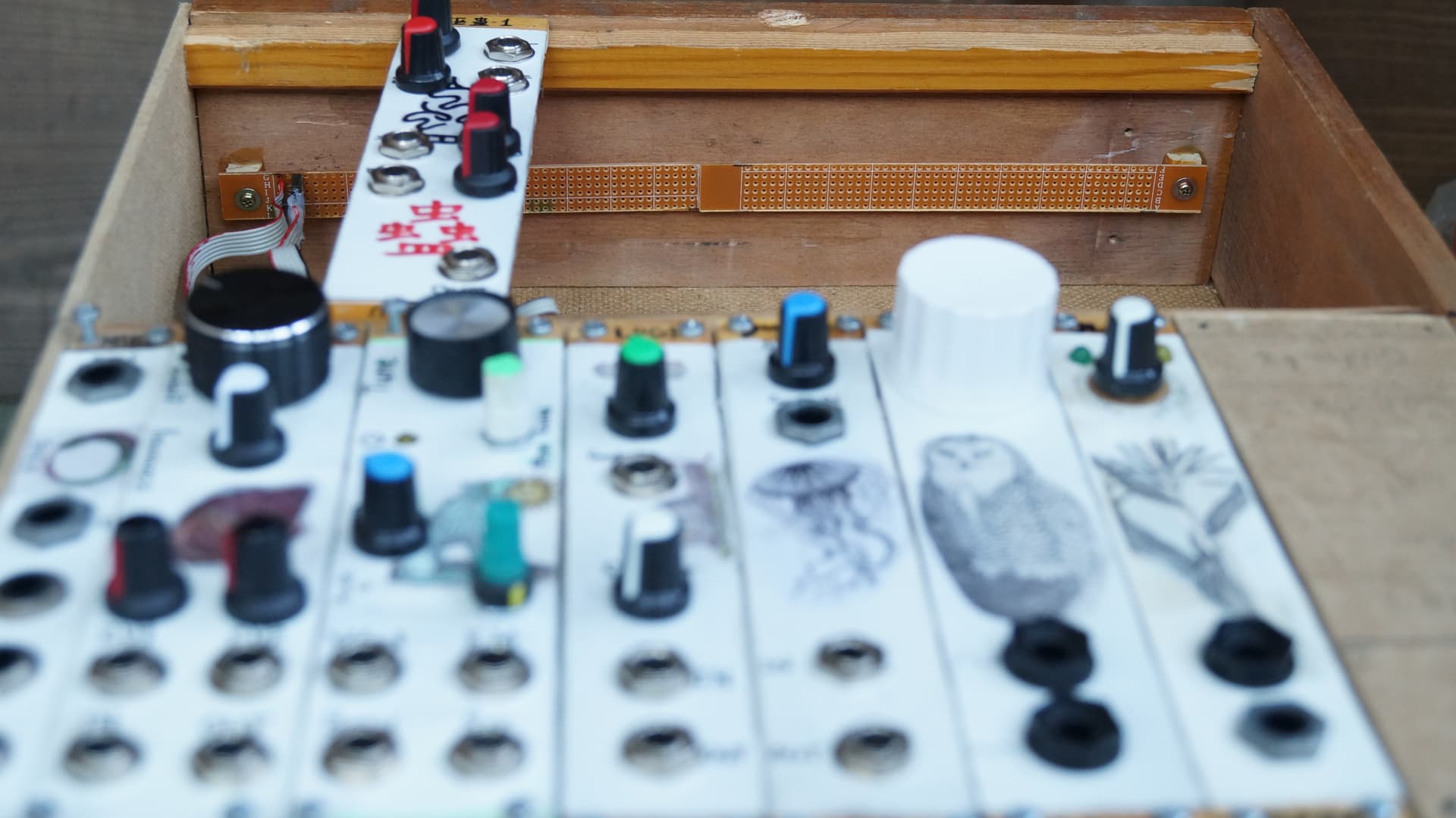
Based on whatever I used for my previous mult. It works, but it’s not in the rig. You see on the previous photo that everything is just… hanging there on pure gravity and friction. When I finish powerlines for the second level of this case, I will screw everything on, but for now it’s just like this. Alright, mult. It is actually 1x4 mult if you don’t connect anything into the second input, so the lower half is normalized to the upper one. I feel like I should’ve done it with my first mult too… This way I have more possibilities and it’s overall more flexible. But oh well.

One more thing before we go to my AliEx adventures…

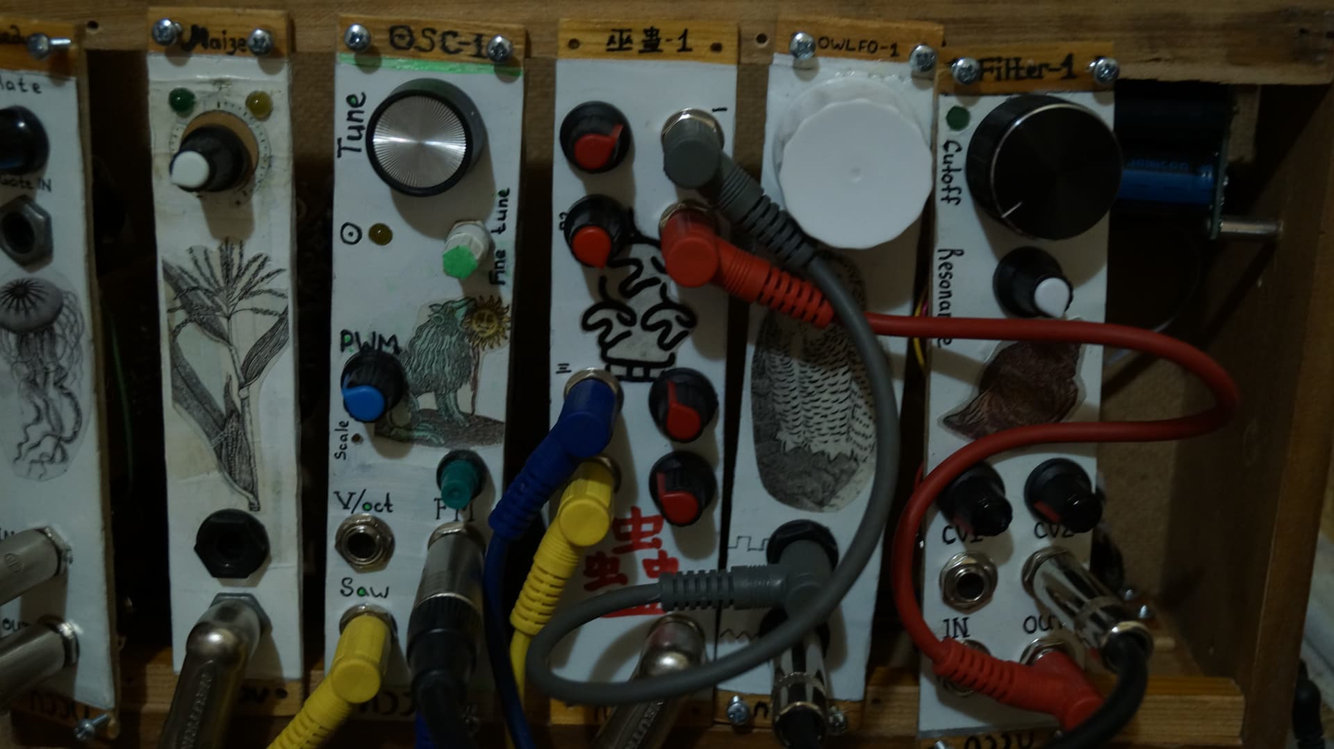
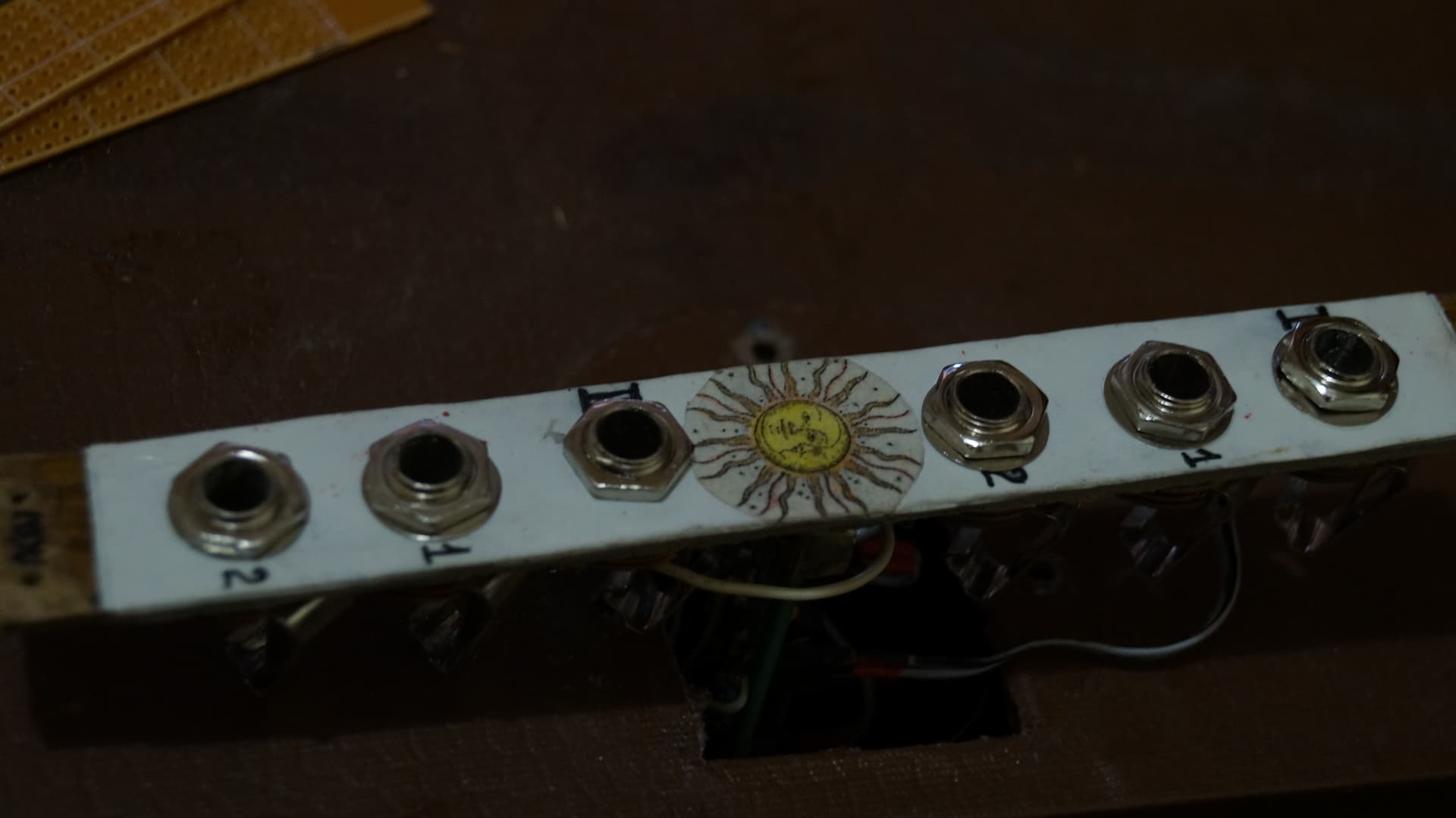
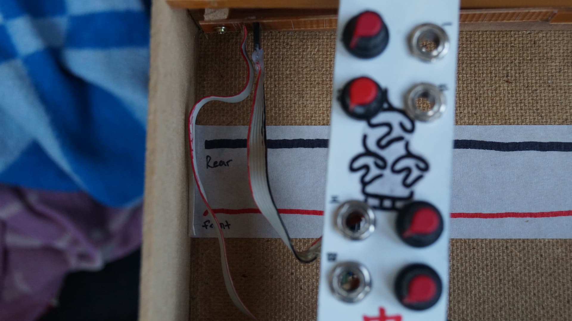
DIY handles! Or knobs if you never giggle hearing this word. It’s bad. Not really centered, not really round… But that’ll do for now. I need some kind of machine that makes things round. It’s expensive though and I can’t see how I would use it when not making knobs. It would be useless… So I need another way of doing this.

Okaaay, now for the AliExpress mishaps! First I’ll list everything I got, as it might help me to remember what I wanted to do with these things… So I got 20 pcs of 6,5mm jacks, finally an STM32 (yes, the blue pill that was mentioned three days ago) and ICs: CD40193 (I bought like a lot of them for some reason, I think I was trying to buy something else, but misclicked and only noticed just now, so now I have like 20 of them) CD4015 CD4016 CD4050 CD4051 (I accidently bought 20 instead of 10) CD4052 CD4081 -everything seems fine with all of the CD ICs- DG411 - it seems fine too, DMM shows that switches are in the 0v position (1 and 4 on, 2 and 3 off - at least that’s what I’d like to believe), which is expected. DAC0800. Now this one was a very weird order. I actually received 9 DAC0800s and one ADC0834. All of the DACs were different. Look!

Very weird! Anyway, ADC is good though. And I don’t need 10 DAC0800s. I Think I needed one or two for the turing machine… But not 10. So that’s alright.

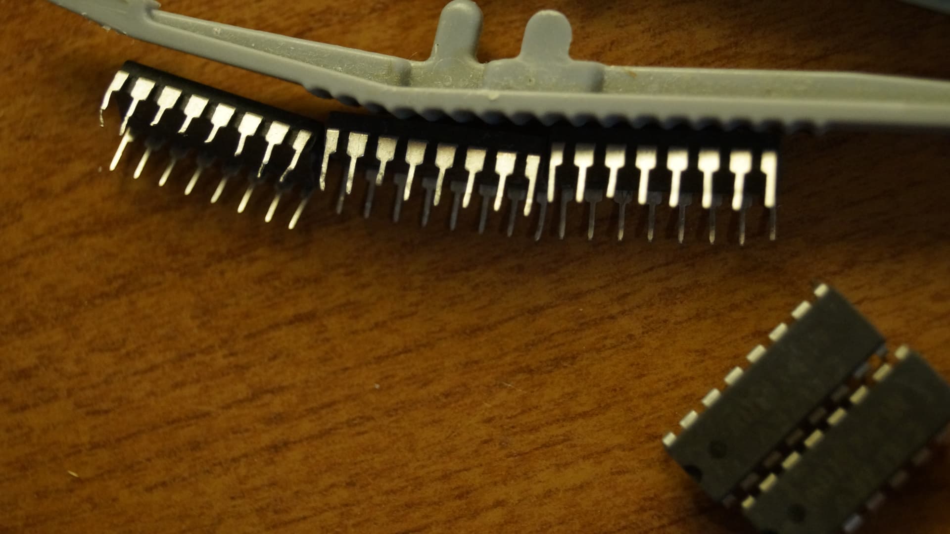
But then we have AD7524s. I’ll show it first

So all 5 of them were desoldered, you can see solder on the pins. And 3 of them had their pins broken or cut off. You can see it on the photo. Given all that I had little hope that they would work at all, so I wrote a complaint at AliEx and I also made a claim to refund. The dispute, they call it. And very quickly I received a result, a judgement of the great Ali court, haha. They’ll refund 100% without me having to send these ICs back. And I didn’t wanted to send it back, cause if one of them works - I’ll use it anyway, even though it would be with some inconvenience. And if they all don’t work and I send it - they will sell it again! So yeah, now I have (presumably broken) ICs and money. That’s my AliEx story for today. The moral is - don’t buy stuff from the small stores.

Although… One thing that I noticed while looking for the envelope these ICs were sent in, is that the person that sent me bad DAC0800 is the same person that sent me bad AD7524! Even though the stores were different. They also had very similar tracking numbers (before they were merged into one megapackage, the Voltron package). So… my journalistic brain expands it to maybe a dozen of different stores, that are actually one store. Again, a Voltron store that is trying to maybe trick the chinese tax system. Or Hong Kong tax system, I am not sure how autonomous HK is now. So I see a conspiracy that should be inspected… I have like more than a hundred of different orders from Ali (both the ones received and on the way here) and I never looked into who sent it. Could it be that there are actually 10-20 big stores with branches that are registered on different people to avoid taxes or anti monopoly laws… But that’s what I will check from now on. Names and emails and phone numbers of senders! Very interesting.

Anyway! I have a little video for you. It’s very dark, but it sets the mood!

A small progress is still a progress!

So power rails for the second “store” of my case, the upper level of it, is prepared. It’s not really done, but what I need now is to make more modules to measure everything and I can’t make them because I ran out of pin headers. Very unexpectedly! I mean, I was I was a bit careless with counting and cutting the pins, so sometimes I would end up with one more pin than needed… And I also used them for my chinese MCUs… And again I miscounted the pins… And I also used them for SOP to DIP converters for my accidental buy of PT2399 SOP microschemes. So yeah, after all it waaaas expected, I guess. Not a pleasant surprise anyway. So now that I am waiting for them to arrive from China I decided to share some photos with you. it’s not beauty shots, but here we go!

Why is it rear? I mean why do you say “ree-ehr” and not “rir” or “rehr”? Like “lead” or “dead”? What’s wrong with english language? It’s so inconsistent

All done. The first “store”, or a lower half of the case is beautiful! With an exception of the rightmost module. Which I thought should be a mixer, but I am not sure now… Maybe I don’t need it here. Or maybe I do! Eventually I would have to decide. But for now It’s like “yaaay, it’s almost done”, completely ignoring this space

GUTS! As you see, I love my hot glue everywhere. It’s like salt. Add it to your dish and it would never shortcut or interfere with another dish! Well… Maybe it’s like salt after all. Anyway, my other way of isolating the boards that seem to be a bit too close to each other is to cover them with tape. But it looks too clean and tidy. Hot glue reminds me of acidic saliva of THE Alien. You know what I mean. Oh! Another word. “mean”, how come it’s not “mee-ehn”? Well, maybe in some accents it is.

Two modules that are not ready yet. (VCA and ADSR). Ideally I need to redo the layout. I don’t like it. I also need to redo the 4069 VCO layout, there are too many jumper wires. And by too many I mean this:

It looks fine, probably, but I don’t want to strip and cut and bend wires for an hour or two. I also need to measure everything. Like how long this wire should be and so on. Hate it. I could just do it with normal wires, but I like the ones that stay bent if you bend them. Like here, see?

image

Normal wires are fine, I am just a bit anxious. Like what if I accidentally rip it? Maybe I should just accept it and do it with normal wires though. They have their charm! I like it when a circuit board looks like it was a part of some serious device! And wires make it look like that. I don’t know why.

I also noticed (few months ago, actually) that my soldering iron is too hot. So I am thinking about buying a soldering station. Need money though. But I bought a portable soldering iron. It’s not really necessary, but it was cheap and the tip is very thin. So I can finally do some micro soldering, haha. Like with PT2399, the SOP version. I have converters, but these chips are not soldered on.

So there’s not much stuff, but a relatively long post. I am sorry for that. Next post will be more interesting, I promise!

1 Like

Sorry for the long pause. I’ve packed all of my modules and components and soldering station (that I bought finally), cause I am moving. I really hope that it wouldn’t be for long, but it’s not really my choice anyway. I have to move or else I would end up in the army and I am not a big fan of fighting especially when I feel that I would be fighting on the wrong side.

So I am packing my stuff and I was doing that for two months already, I think. I’m very slow, haha. I will continue this thread in august, I hope. Maybe in september if things would go slower than I think. Next two modules would probably be based on microcontrollers, so it’s very easy to make. And I’d already prepared the faceplates. See you soon!

2 Likes