Hope the move works out well for you. What a nasty situation to be in. Makes me grateful that I never had to worry about anything like that. Good luck!
I’ll start with a question. For the people that don’t want to read long texts: is it fine to move the bypass capacitors to the power distribution strip? In my mind there’s actually no difference where you put it, but maybe there is some esoteric knowledge that I lack.
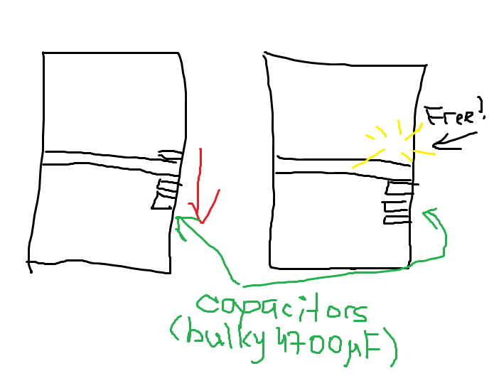
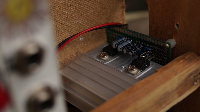
Alright, I am kinda back, I think. I am still here in my city, so the whole escape plan didn’t work, but that’s okay, probably. This summer I didn’t do anything soldering-related. I ordered some stuff on Ali, made some front panels, but never actually touched the soldering iron. A week or two ago my friend was visiting me and we played with modular a bit. Next day I noticed that the upper row acts weird. It only has two modules for now: mixer (based on NLC schematic. I think it’s pretty much just the regular DC mixer though) and double mult. So both of them were outputting +10v constantly. So after checking the modules, cause that is an easiest thing to do (and also I noticed a mistake in my soldering, so that was actually a good call) I concluded that the problem is with my PSU or distribution lines. And It turned out to be true. For some reason one of the upper row strip jumper got desoldered, so I fixed it. While I was at it I decided to move my PSU a bit lower to free some space for the upper row modules. Here’s an accurate image, almost a photo:
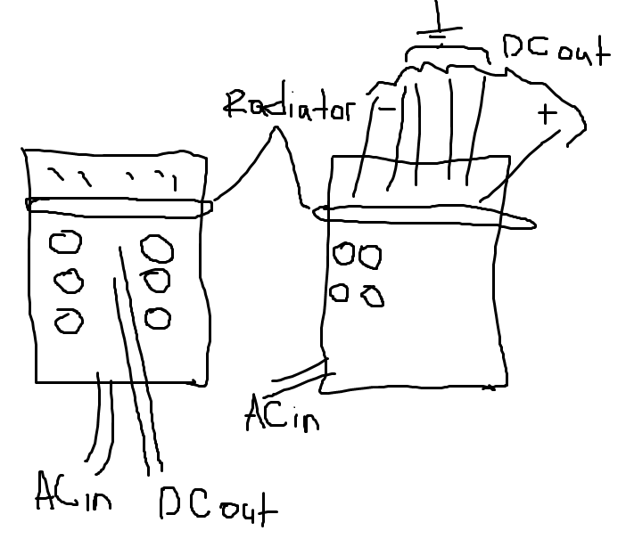
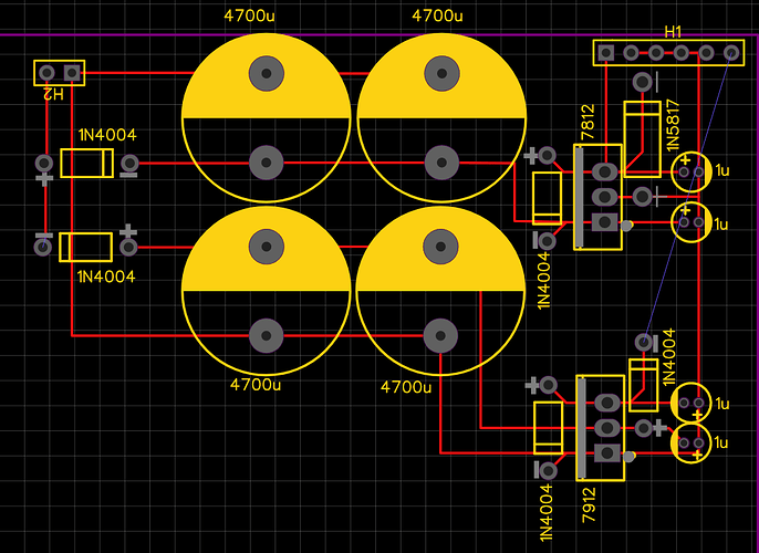
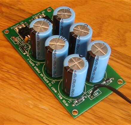
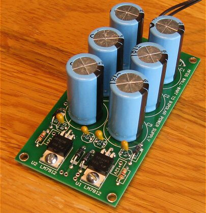
So after all these manipulations I turned the power on and 7912 said bzzzzzzzzzzzzzzz. C’est la vie, I guess. Nothing is predictable and blah blah blah. I am still not really sure what caused it, but there’s a possibility that when making this PSU I messed up. It was very beautiful! If there was a contest for the ugliest PSU, it would be on the last place. The main problem with it was that I didn’t have flux when I was making it. I also didn’t have much experience making stuff, although I did know how to solder. That’s complicated! Anyway, it was shit. It was very bad and I am surprised it last that long. I was planning to redo it or to make the new PSU, so that’s fine! Now I am redoing the whole layout. so it would be a bit more slim and compact. I also changed the schematic from Moritz Klein’s to MFOS with a modification suggested by Rich Holmes. Here’s another picture! A bit schematic
At first I wanted to change one shared radiator to two radiators for each regulator, but I decided that it is actually okay to have a shared one as long as there’s an isolation layer (the silicon thermo thingy). So that’s where I am at right now. Redoing what I did wrong. After that I’ll check the power strips again, just to be sure that the problem was indeed with my PSU. And then I’ll check the modules. They should be okay, at least I hope.
Plans for the near future (not in the chronological order) for THIS case:
- Clock
- Euclidean Seq
- 8 step Seq
- ADSR
- VCA
- another VCO
- another VCF
- probably audio in/out module, maybe just Audio out OR tinkle by NLC OR another VCO
- another mixer, probably stereo for audio purposes.
And after that this case would be complete. Not like “it has everything I need” more like “there’s no space to fit anything anymore”. After that I am thinking about making a semimodular synth, like MS-10 or MS-20 or Minimoog. I really love modulars, but I can’t drill the holes for them in a way that they would be movable. Like I can’t swap VCF and VCO even though they are similar in size. The holes for the screws are not lining up. And it’s not this simple for me to drill the holes perfectly at the same spots for each module. I guess if I had a drill station or whatever you call it, that wouldn’t be a problem, but as I do everything by hand… yeah. I’ll try to find another solution though, like drilling bigger holes in the front panels and using washers or something… So maybe semimodular system isn’t the best of my ideas, cause when I think about it, that would be a pain to troubleshoot and fix. And also I would have to plan everything beforehand. So when working on PSU I would have to actually think about the whole system, so it wouldn’t get in the way. It sound like a fun project though. Maybe I will do this at some point. I can’t decide. For now I have to finish this case.
A cat
Happy cat, its always good to see a happy cat.
You want to move the 4700uF caps? That won’t leave much on the psu, just the 7x12’s and a couple of diodes, could you not just move it all?
I would suspect you will not notice the difference if you just move the caps.
Nice to see you are back building ![]()
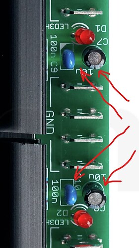
Hi, Dave! No, not the 4700uF caps, of course. I mean the 10uF caps from the modules.
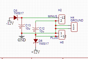
Like C12 and C13 on the screenshot above.
I also moved 4700uF caps though! But they stay on the PSU. I just relocated them a bit to free some space for the jack sockets of my planned mixer
Interesting! I just watched the first one, I’ll watch the rest later. Thank you very much!
The bypass caps should be close to the chips, not all the way over somewhere else. Proper grounding is a bit of a mystery to me, though, I will confess. Of course anyone who doesn’t think grounding is a mystery is either ignorant or they are super knowledgeable.
Yes! That’s true! I always put the bypass caps that are meant to go with chips either under the panel or just outside the panel (panel for a chip). Usually it looks kinda like this:
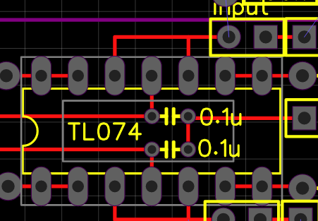
I like to make it as neat as possible, when I have patience to do it, haha…
My question though is about other bypass caps. The ones that I saw many people using on the power connection where electricity “enters” the module. I guess their purpose is to smooth the voltage. And if it is, I just don’t know, I’m not sure you need them on the board… Maybe they would be fine on the power distribution strip\line. But maybe they have another purpose and as I am not really smart, it’s not obvious to me, so I hesitate to move them there.
We place caps near the power line input to a PCB, to have them work as a power reservoir for that PCB. bypassing the (power-ground loop-) inductance of the wires from the main power supply to the PCB.
This video featuring Eric Bogatin is quite good, and maybe better than the Dave Jones videos.
also,
" The methods for choosing bypass capacitors typically follow decisions of tradition instead of optimizing for any particular circuit"
foreword to the classic article Intersil AN1325
Oh! This one is much more clear!
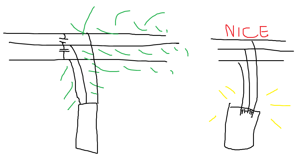
“We move the surrogate power supply closer to the chip. It’s decoupling the rest of the inductance in a system”. Now I see… So if I understand it right, if you put it on the power distribution line, that would eliminate only part of the inductance. In my mind, maybe a bit naively or oversimplified it looks like this:
So you either put them everywhere on your power distro, to cut it in discrete short distances or you put it on your board… I see. Well, maybe a handful of them on the power distro line wouldn’t harm too… But I am a cheapskate, hahaha
PSU fixed! Although after testing it, it became obvious that the problem was elsewhere, not with PSU itself. As I like to write, I’ll write you the whole story!
As I mentioned before, my 7912 said bzzzzzzzzzzzzz for some reason, probably because when moving it (and I also used shorter PCB stands) I shorted the caps. This version of PSU was seriously scuffed. I forgot to take photos of it before dismantling it for good. So I’ll search for the old photos here, in this thread and then I’ll also draw the side you can’t see.
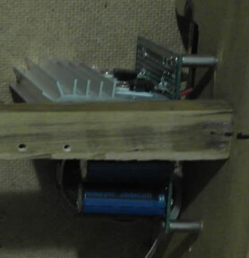
I don’t know why I decided to use ceramic caps here. Well, it didn’t cause any problems to be fair. And the only problem it eventually caused was totally my fault. I still don’t really know the difference between different kinds of capacitors. I know about polarized\non-polarized, but what is the difference between ceramic and film ones? Or between electrolytic and ceramic in this situation? So in my defence I still think it was okay to use ceramic ones here… Especially when it’s this close to voltage regulators. Maybe I am wrong though and you actually HAVE to use electrolytic caps here. Cause every time I check photos of other DIY PSUs there’re no ceramic caps there.
Anyway, here’s a drawing of what was on the bottom side of a board:
The thick lines are the solder traces. And I took some artistic liberty when drawing it, haha. I can’t remember the exact paths… But there was a loooooooooot of solder. SO much of it that when cleaning the board after desoldering the components I had to use a heat gun. And to make it faster I set the temperature to 400C. As a result the board got burned in some places, hahaha. Well, I don’t really care about it. It doesn’t affect the performance. Maybe it would start to crack there in 50 years or so. I don’t know if I would be there to witness that.
Anyway, the new layout was like this at first:
I decided to change few things while working on it. I changed some of the diodes to the equivalent ones. Namely I changed the upper left one, the one that goes through 4700uF caps to the input of 7812 and the bottom right one, between input and output of 7912. Also I couldn’t find 5817 at first, so I was thinking about changing it to 5819, which wouldn’t be a problem, but eventually I did found 5817 in my disorganized diode collection, so that’s even better, it’s as close to the plan as it gets.
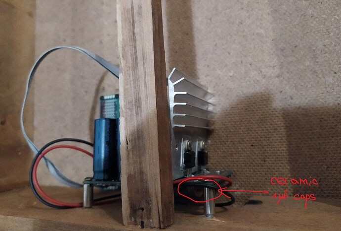
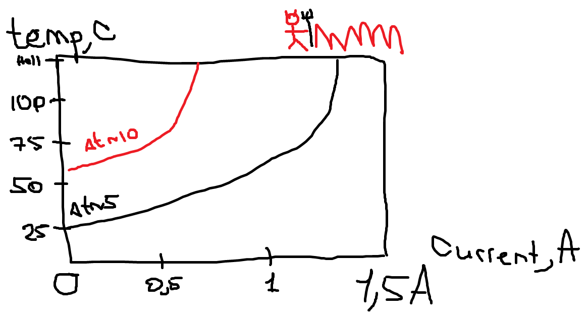
I also moved the 1uF caps to the middle. My concern was that I don’t really know how warm i gets near the voltage regulators and my caps are rated for 85C. I checked the datasheet and couldn’t find any graphs that are easy to understand. Like a stupid temperature as a function of current, cause delta t should be around 2-3C as my transformer outputs 14-15v. Which is perfect btw. So that sets the temperature on the lower side of delta t dependence. I mean in reality it would be more than 3. Maybe even 5-6V, but whatever. It is low. So current is a thing to watch out for. And I couldn’t find the graph for it. Like… let me draw what I mean
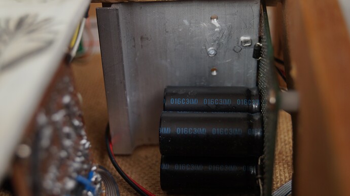
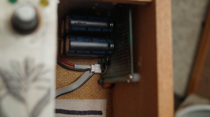
Easy, right? Couldn’t find it. Anyway, I decided to move the caps away from voltage regulators for that reason. They are still close to 7812 and 7912, but not in a direct contact as was on the plan.I decided to make it prettier and easier to service. That’s why I also got rid of the big connector that you see on the upper right side of the schematic. Instead I just soldered the wires to the outputs of voltage regulators and the ground bus (I mean the long wire on the right). So everything is easily detachable, except… well, the voltage regulators are not this easy to service, cause I used their leads to connect them to other stuff. So I bent them and that is a thing to consider when removing them if things go wrong one day. Otherwise it is much easier to desolder and change the components if needed. I forgot to take photos again, so I’ll take some shots of it inside the case and that would be my smooth transition to the first and only problem with this board.
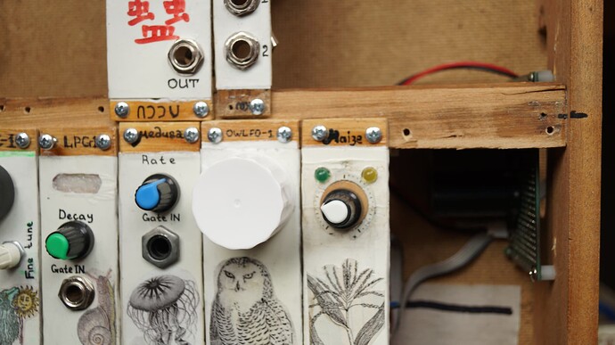
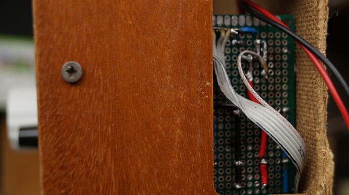
Cool, right? A lot of space both in upper and bottom rows. I got rid of 2 big capacitors, cause apparently it is okay with just the 4 of them. Also notice the shorter PCB stands. It almost looks like I know what I am doing! Anyway, do you see the white connector on the last photo? I thought that it would be supercool to have it. I don’t really need it right now, that was an experiment and this experiment wasn’t a success. Cause it seems like these chinese connectors are very loose. The connection is not strong… I’ll try to find a solution to this problem, but it doesn’t look good. Probably it would be fine if I fix the wires to the case somehow… But even that is not guaranteed.
Alright, I checked it with my DMM and it seemed to be fine. So I connected it to my system and immediately lost the -12v line. No bzzzz, no smoke. Just no -12v. Ground is okay, +12v is okay, just -12v is bad. So I checked the connectivity between the connector that goes to the power distribution strip and PSU… And yeah, there was no connection. The wire got desoldered from a connector on the power distribution side when I shorted the previous version of my PSU, probably. I resoldered it and it fixed the problem (which was the main reason I re-did the whole PSU btw) So it might look like I did it for nothing, but I actually enjoyed it and it was planned anyway, so that’s okay.
To other news. Remember when I said this?
It looks like I don’t have much space for everything even now. So I am thinking about making just two modules in addition to already planned modules (Clock, Euclidean seq, VCA, ADSR and audio mixer). The situation is more complicated, cause the upper row feels like it could fit 3 modules if I am careful, but they shouldn’t be too wide… So I could probably fit 8 step sequencer if I use the smallest potentiometers, which I do have, but they are PCB mounted, so not the ones that you screw on the panel, what I usually do. So you have to do it on the board then attach this board to the front panel and after that you also have to attach the main board to the module… I know it sounds like I am over complicating things, you saw these designs on Eurorack modules millions of times, but that’s first time for me and I do all the thing by hand, so I am not really sure if I could align the pots and the holes on the front panel correctly. And after that I also should fix the board… (fasten the board?) to the front panel. That’s too annoying. But choices are: either you go with the space management route or you make two modules for the space that clearly could fit 3 of them… I have to think about it! I need to make the planned modules first anyway, so I probably have a couple of months to think about it.
Anyways, that is he end of this update. See you next time!
Update about ceramic caps.
I was managing the tabs in my browser and noticed that Ray Wilson used ceramic caps for his PSU.
from the ST 78xx series datasheet p23:
“. In many low current applications, compensation capacitors are not required. However, it is recommended that the regulator input be bypassed with capacitor if the regulator is connected to the power supply filter with long lengths, or if the output load capacitance is large. An input bypass capacitor should be selected to provide good high frequency characteristics to insure stable operation under all load conditions. A 0.33 µF or larger tantalum, mylar or other capacitor having low internal impedance at high frequencies should be chosen. The bypass capacitor should be mounted with the shortest possible leads directly across the regulators input terminals. Normally good construction techniques should be used to minimize ground loops and lead resistance drops since the regulator has no external sense lead.”
A ceramic capacitor can be microphonic, that’s one reason to avoid them. Unless its dielectric is of type C0G/NP0, these types are not microphonic (or at most microphonic to a very low degree).
So it’s not this important then… I don’t think my whole system would reach even 1A. I guess I have to find a way to measure it at some point though… Anyway, that’s a good info! Thank you!
So they are kinda piezoelectric? Well that makes sense to avoid them here then… I am interested in which cases they act this way though… Or is it all the time?
I would not use ceramic capacitors as microphones ![]() they are not very sensitive In my experience.
they are not very sensitive In my experience.
Doepfer use ceramic 100nF (and electrolytic 10uF) capacitors on the output of their LM317/LM337 Kit PSU. I can’t see if it’s NP0 or not. (I don’t have the schematic, but i’m guessing from the pinout that it’s LM317/LM337)
or the 100nF could be tantalum, now that I look again, I see the silk-screen shows polarity.
Yeah, they might be polarized… Although I don’t see any indication on the capacitor itself, to indicate minus or plus… On one photo I can see either 100 or 104 marking, but no + like to indicate the positive lead. And I can’t find any better photos. This whole investigation is stupid, I spent 20 minutes looking at photos in google and reddit trying to find out what capacitor it is… haha. Well, they are in parallel, the 100nF and 10uF ones, so that doesn’t really count after all. I think the smaller ones are to filter the noise and the bigger ones are to smoothen up the signal. If I remember correctly what smart people were saying on the video about bypass caps…
Nice clock let’s gooooo
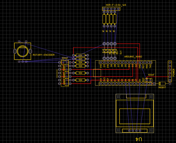
Note that I forgot to add a 1uF/10uF/whatever value you like bypass cap on the power rail. I just ignored it for some reason. There is 10uF cap on the actual board, btw! So besides this stupid mistake this schematic is almost identical to Richard Holmes’ clock schematic.
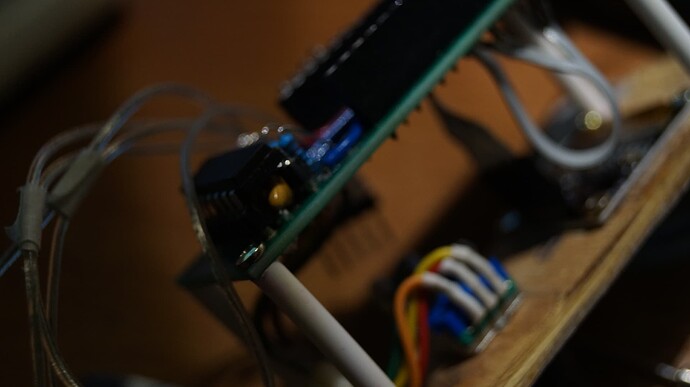
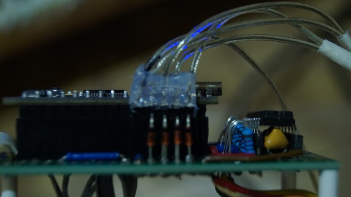
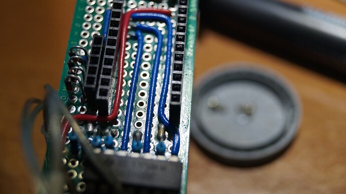
I only cut some unnecessary stuff out. Like tap tempo button - who needs that? 6 outputs - 4 is enough! On-Off switch - just disconnect the power. LEDs on the outputs - blinking is nice, but you know what’s even nicer? Forgetting to drill the holes for them. Not like it ever happened to me before (it did)… So I simplified it to bare bones. And it allowed me to actually think about beauty. I tried to make it as pretty as it could be. And it is kinda cute! Look:
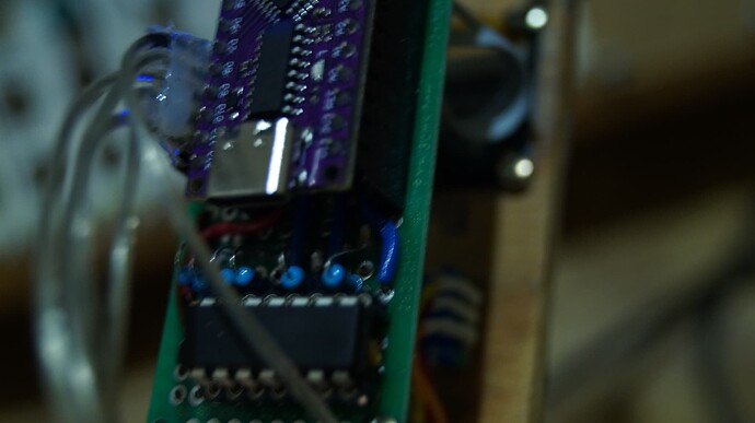
Right after soldering everything I took my chinese arduino clone and uploaded a program written by Richard Holmes: no changes, nothing was deleted or even moved or renamed. I intend to do it after writing this post here. Cause I expect long hours of reading manuals to libraries and C or C++, I don’t even know yet what it is. Now let me walk you through my delusions. Eventually and ideally it should work like this: first output is whatever bpm is, all the other ones are divided by different variables that you set by turning the knob. So basically Clocked by Impromptu. Maybe I even find a way to implement swing. In reality though I would probably cut everything I haven’t used, rotate the image 180 degrees for my upside down screen (more on that later) and call it a day.
Back to the point where I just uploaded the clock sketch and plugged it in. It wouldn’t be my project if it worked as intended right away. It didn’t worked at all at first. Turns out there was a cold joint on 5819 (5817 on schematic).Ah yeah, I changes 5817 to 5819 and I planned to change a bunch of 4733a to default no name 5v1, I even contacted Richard Holmes about it, I asked him if there’s some esoteric reasoning behind using 4733a there. He said it’s okay to change it to 5v1. So I was planning to do it, but suddenly found a strip of BZX5v1 which were listed as a perfect replacement to 4733a. Cool story, right? Unexpected turns and sudden revelations… Anyway, back to cold joints.
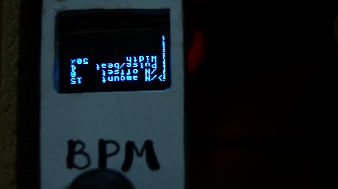
So I reflown (Reflew? Reflaur? Refloir?) Whatever, I fixed the problem, plugged it in and it showed me something on the display! Nice nice. There was a problem, which I expected, to be honest… I knew it would happen, cause I have problems telling left from right, but not up from down. So I knew that the display is mounted the wrong way, upside down. I did it intentionally, expecting to fix the problem later in the code (and I still don’t expect any difficulties with that)
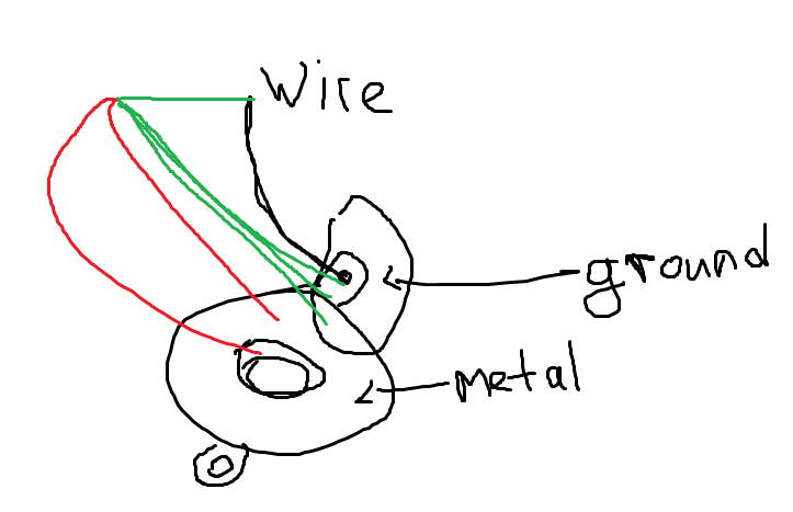
What I didn’t expect was that there was another cold joint or… I don’t even know what it was. So my grounding goes like this now: I have one wire that I connect to one jack socket and then it just distributes to other sockets via aluminium face plate cover (just to remind you, the face plates are made of plywood, but I glue aluminium on top of that). Continuity looked fine at first. All the sockets’ ground thingies are interconnected. But for some reason the first socket that I soldered ground wire to, appeared to be haunted, there was some serious poltergeist.
Green lines are showing continuity, red ones are Open Line. I don’t know what it was. It showed no continuity between things that are visibly connected. Maybe there is a crack in metal or something… I don’t know. I redid the soldering and it works fine, at least for now. I expect this to fix the humming problem that I experienced, so I haven’t even tested it yet. I think it should be fine.
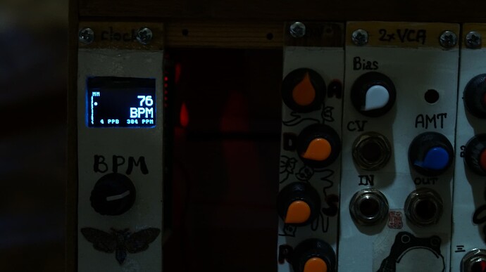
Another problem with spooky scary ghosts! When I managed to make the module work, it started to glitch a bit: the screen that you see on the photo started to appear by itself. I think it might be another grounding issue or even the same issue… So I don’t know yet how to fix it and what’s actually wrong.
Anyway, not it’s time to read the manuals! See you later
mkay,
-
fixed the grounding (still no luck with one particular socket’s contact, had to solder a new wire to another socket to fix this problem…)
-
Rotated the image, or more like flipped (“setFlipMode(1)” instead of “whatever_R2”). No idea what’s better. I just arbitrarily picked this option
-
Commented most of the stuff I don’t use and maybe tomorrow I’ll start to rewrite the code, so I could overcome the lack of an additional button (I probably don’t need a choice between incremental/Maelzel Metronome modes. I usually write music at 60 to 100 bpm. Rarely faster than 120, So I’ll probably set the default bpm to 80 and go from there. I am not sure if I need to stop the clock too… I will probably leave this feature, but move it to “long push” thing and “short push” would open a menu for divisions. Not sure how to do it all of that yet, haha)
