DIY Module Front panels (two questions and a big tangent)

…consists

of a highly conformable and slightly tacky silicone elastomer sheet filled with thermally conductive ceramic particles, which helps provide enhanced thermal conductivity and excellent electrical insulation performance.

That is interesting that it is a ceramic filler that is thermally conductive.

Perhaps ceramic = “hexagonal boron nitride nanoribbons (BNNRs)” - can approach 1700–2000 W/mK (source)

1 Like

Power supply on the Voyetra-8 (on the right), is one of the few hardware systems in there that I designed myself. Even ordered the custom heatsink!

5 Likes

Although I worked a lot with silicon nitride in the semiconductor industry, I was unfamiliar with BNNRs as I have been retired from that industry for 25 years now and a lot has happened in that time. BNNRs sounds like a “topological thermal conductor” and is fascinating. It has aspects of being a topological thermal diode approximating Maxwell’s Demon.

I use acryllic for my DIY electronics needs. Non-conductive, non-flammable, very easy to work with. All it needs is a measured scoring with a sharp knife followed by a good bonk, and it splits perfectly straight. It’s easy to drill, too.

1 Like

Ah, I forgot about acrylic! Back when I was making synths with aluminum panels I had a job making electronic test equipment at the university and we used acrylic panels. You are right about that stuff. I think to label it we just wrote on it with permanent maker - I don’t quite remember.

1 Like

That’s what I do. Purple paint marker on blue acryllic looks pretty decent, and a steady hand lets you draw up a decent panel without anything too fancy. I’ve been working on building a DIY modular out of a plywood box “case” and acryllic panels drilled into the wood.

Could you share some pictures? I don’t think I would use acrylic now, but maybe for the future project…It sounds… decent and inexpensive, haha

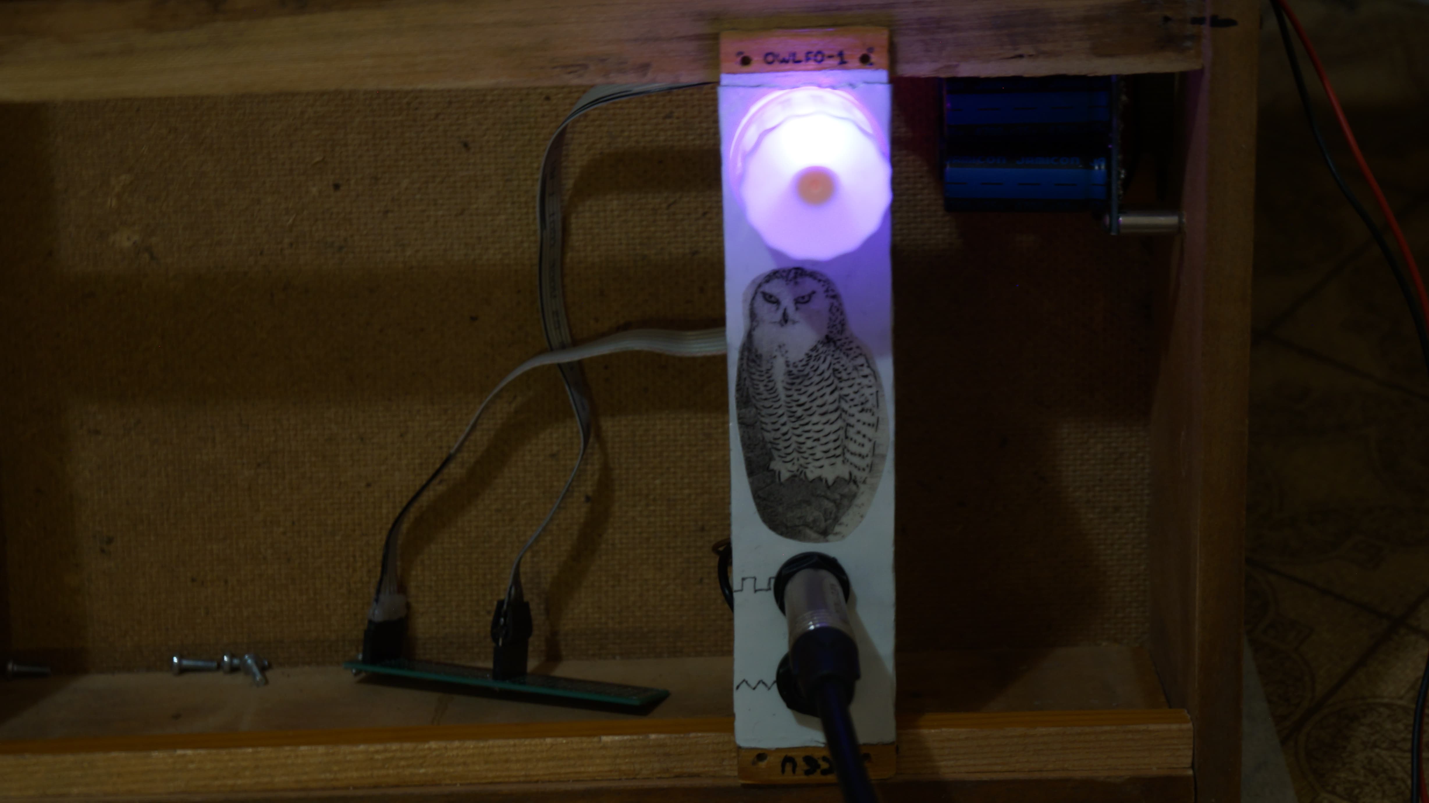
Alriiiight. So here’s the result. It is a bit ugly, but it has a story

And here’s this story!

I will start with the electronics side of things. For some reason I just couldn’t make the pink noise work. Something is broken or maybe I was sloppy when soldering, but here’s what was happening: as long as there was only the white noise circuit on the board, everything was perfect. Then I added the pink noise part and everything got weird. White noise wasn’t loud enough, pink noise was just clipping all over the place, so it wasn’t even pink. Alright, I though, that’s probably because I accudently made a tin bridge somewhere. So after two days of trying to fix it, I decided to just redo everything from scratch. White noise - perfect, pink noise… not okay. Again. So I decided to re-read all the schematics and info… Nothing, everything is correct, but it doesn’t work. And that’s why there’s no pink noise here, haha.

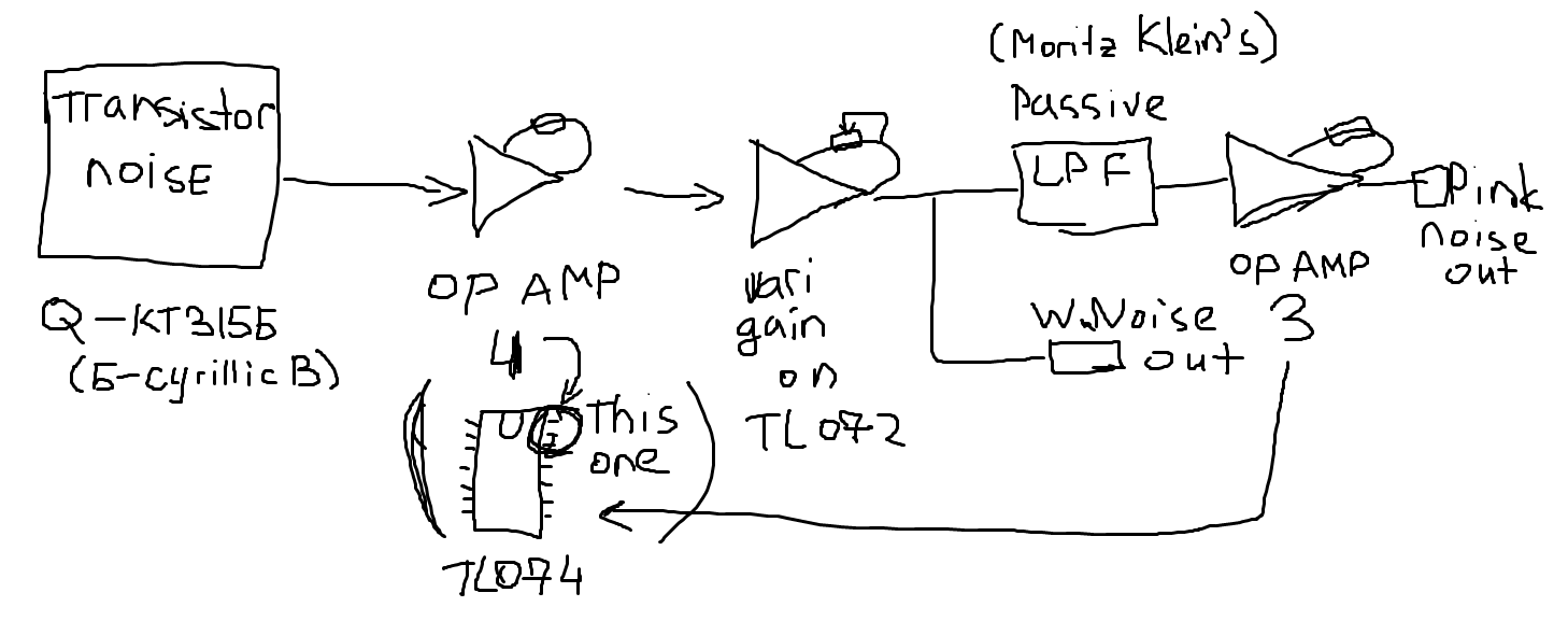
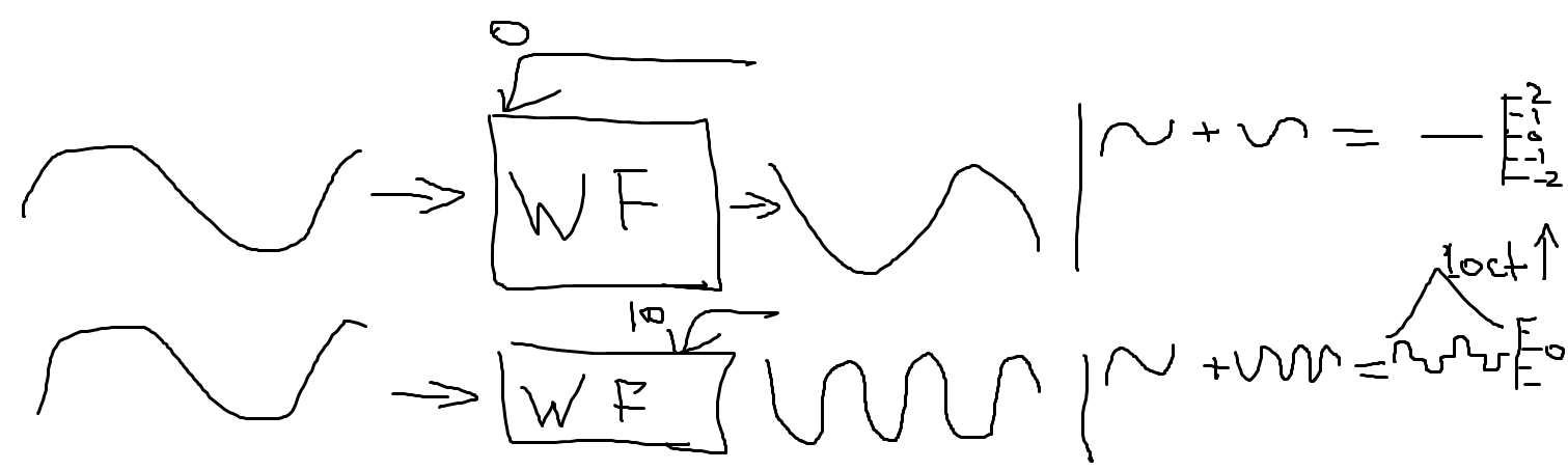
Just for the people who would like to diagnose the problem (not that it matters now) - here’s a simplified schematic:

Sorry if it is confusing, but I binned the original detailed schematic after a nervous breakdown (that’s not true, I just binned it because there was no need to keep it).

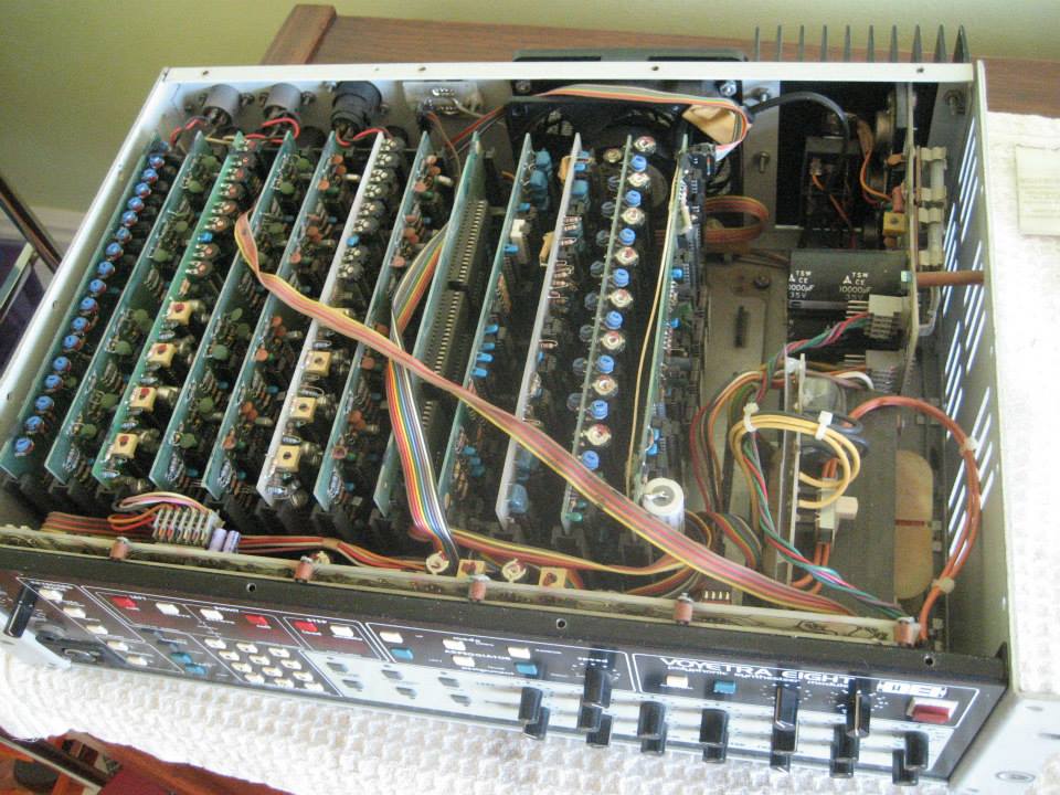
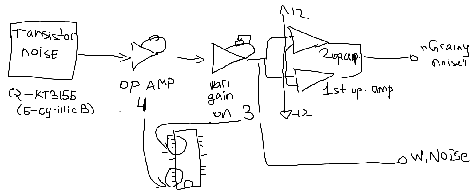
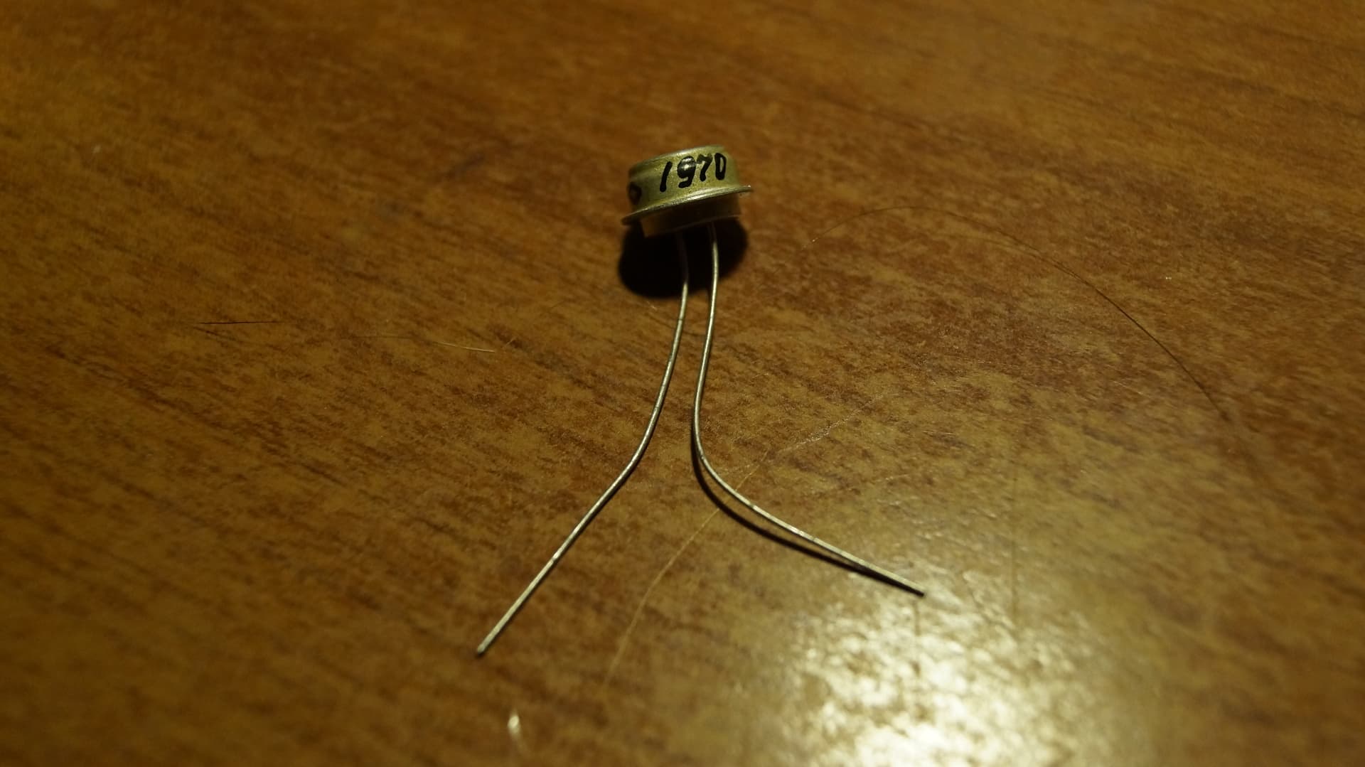
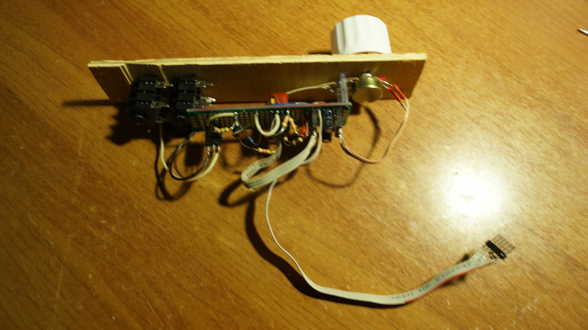
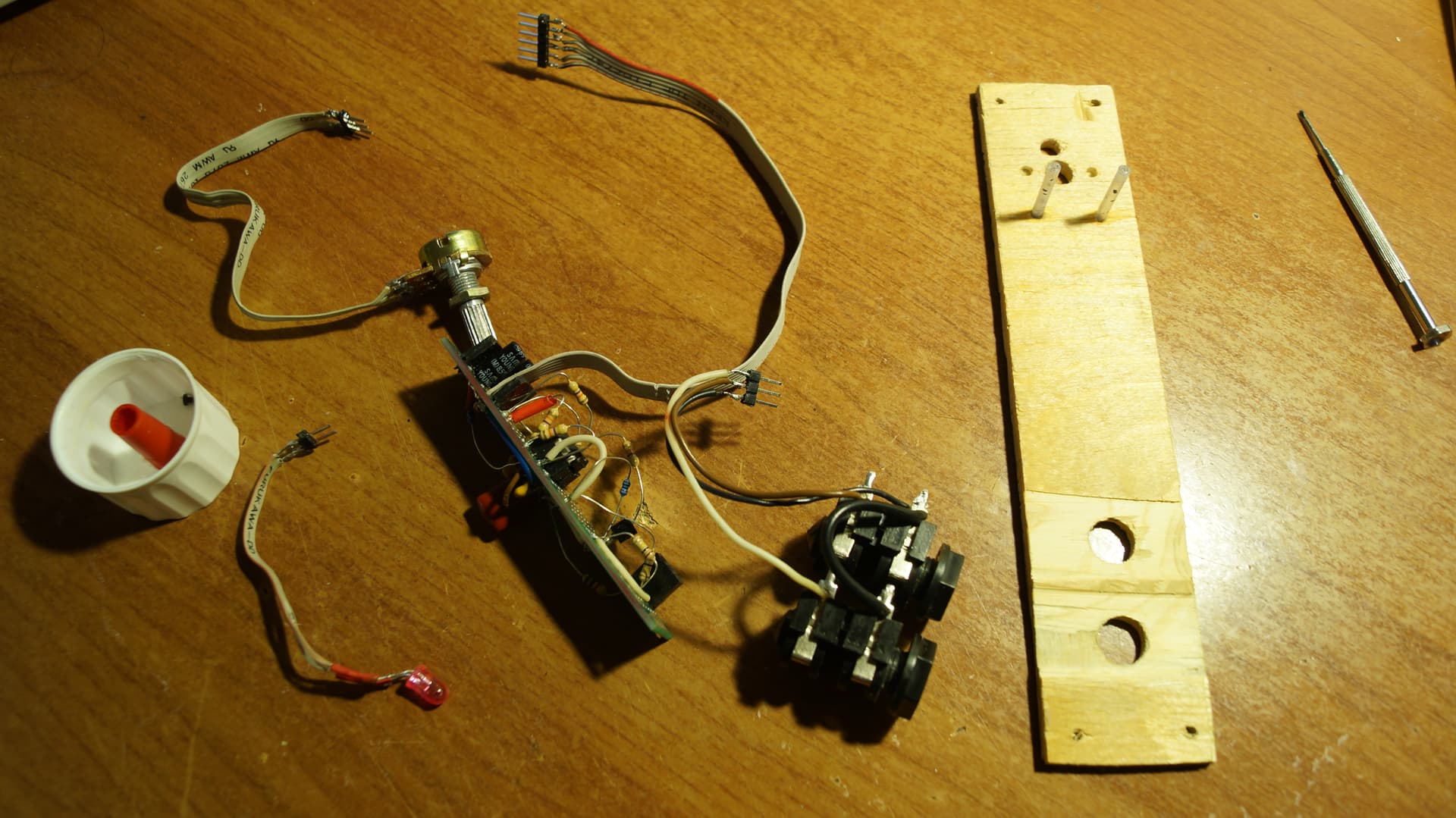
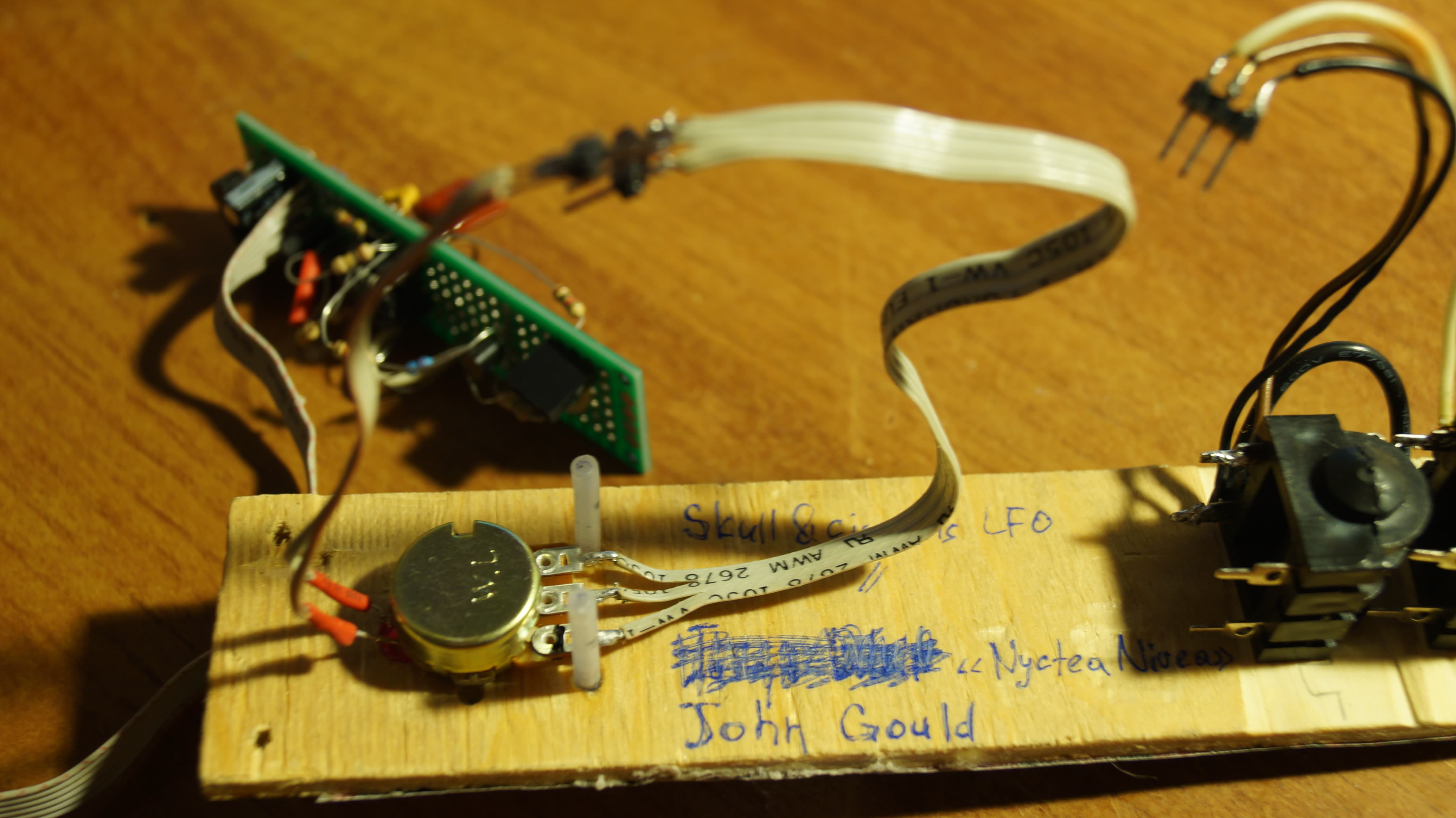
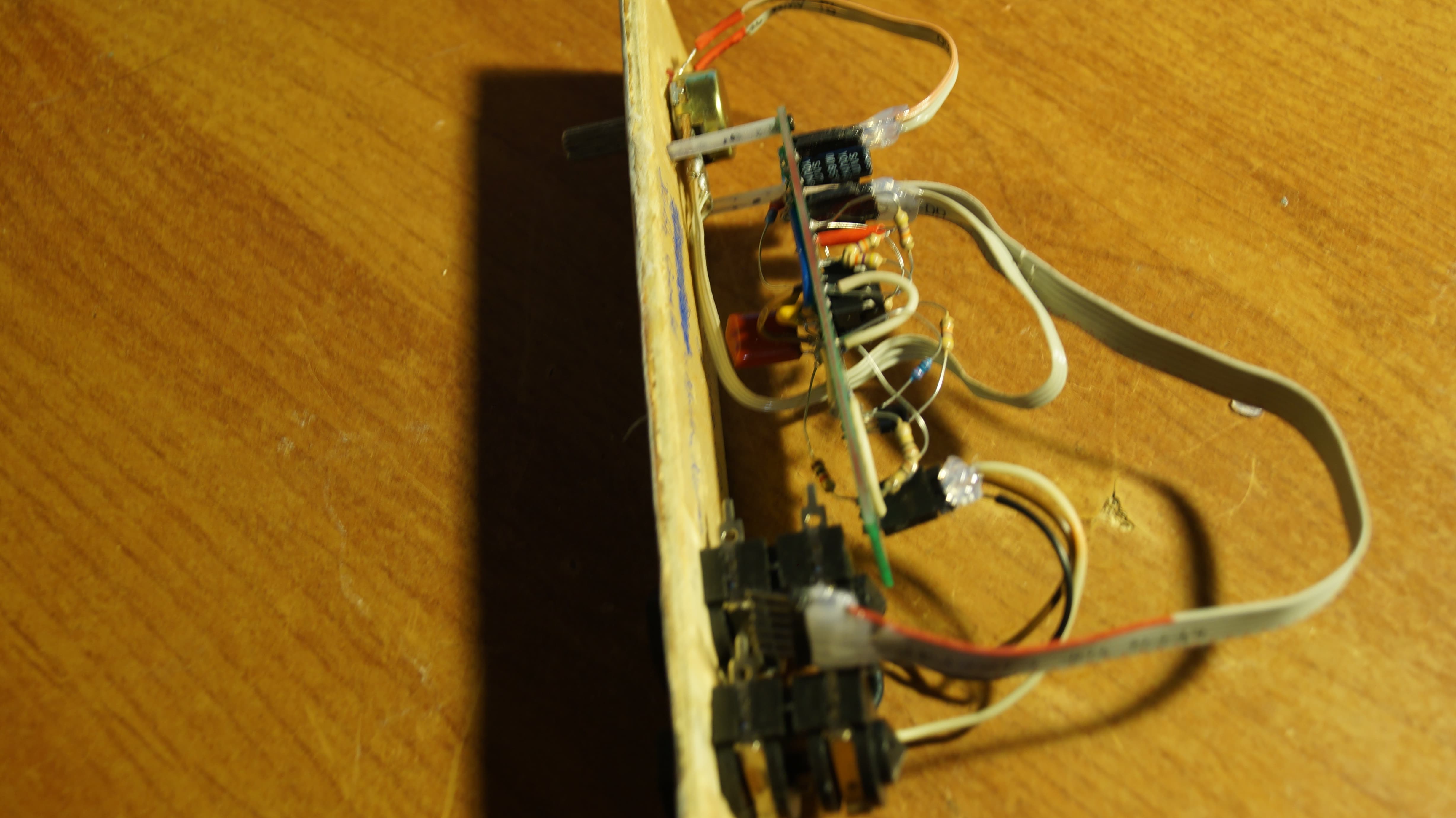
Alright now we have this situation (and everything works):

As you can see, there’s no TL072, so could it be that it was faulty? I am not sure. I don’t know. We’ll see when I try to use this chip later for something else

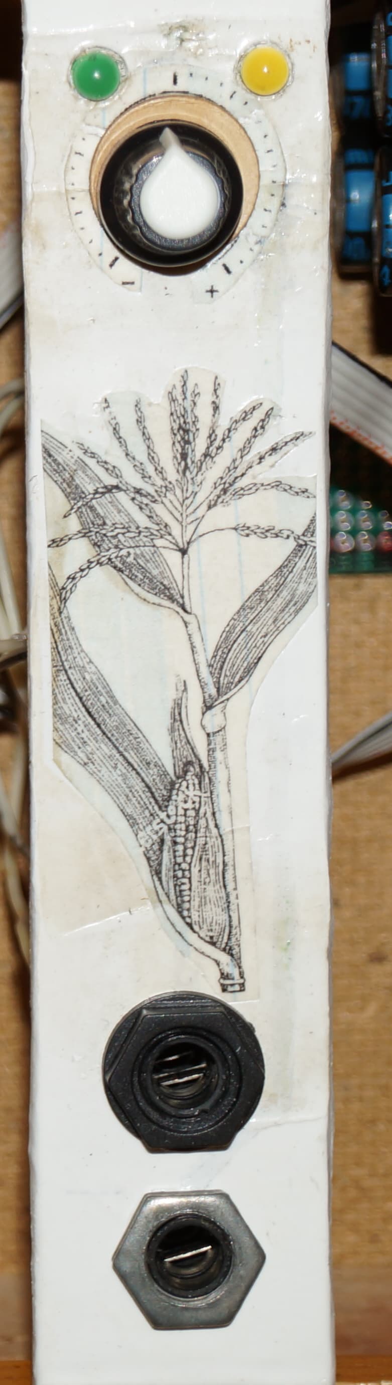
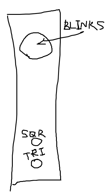
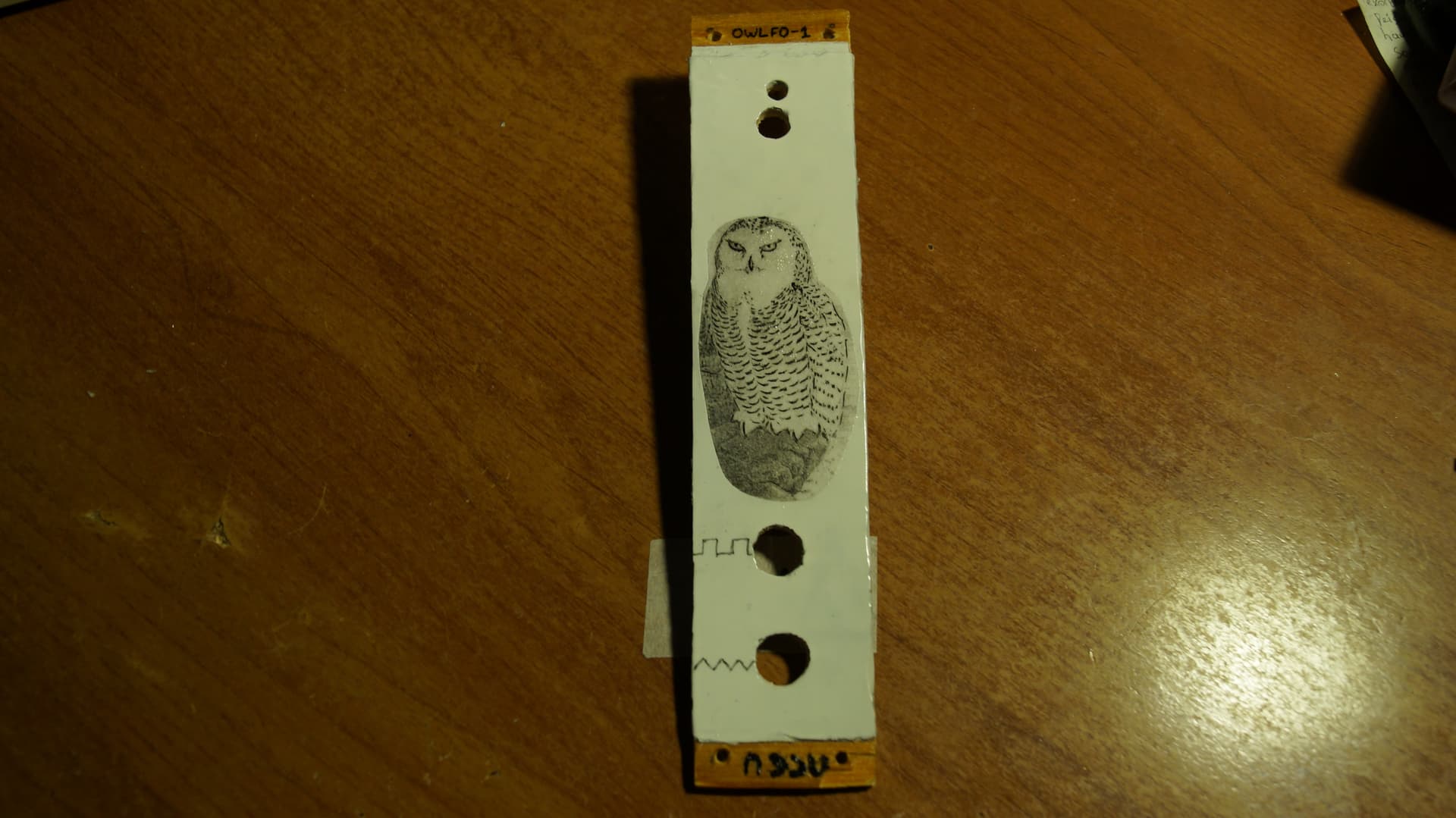
And now the front panel saga!

As you see, there’s a piece of plywood. Yeah, I decided to go with this plan. So I took plywood and just glued a layer of aluminium from an old beer can on top of it. There’s a reason why I did that. I just don’t like how painted wood looks. So I needed something smooth and unicoloured. And aluminium cans is a great resource, it’s very easy to find, easy to paint and easy to throw away if something isn’t right with the size or quality or… something. Also it looks like you need just one layer of paint to make it look great. Bad sides are: it’s not this easy to glue it onto plywood, it’s thin, it has pretty sharp edges, it splinters if you are not careful when cutting it out from a can. Also it takes paint well, but keeps it not this well. What I mean is that you can scratch the paint layer easily. Too easily. So that’s why I repainted it second time.

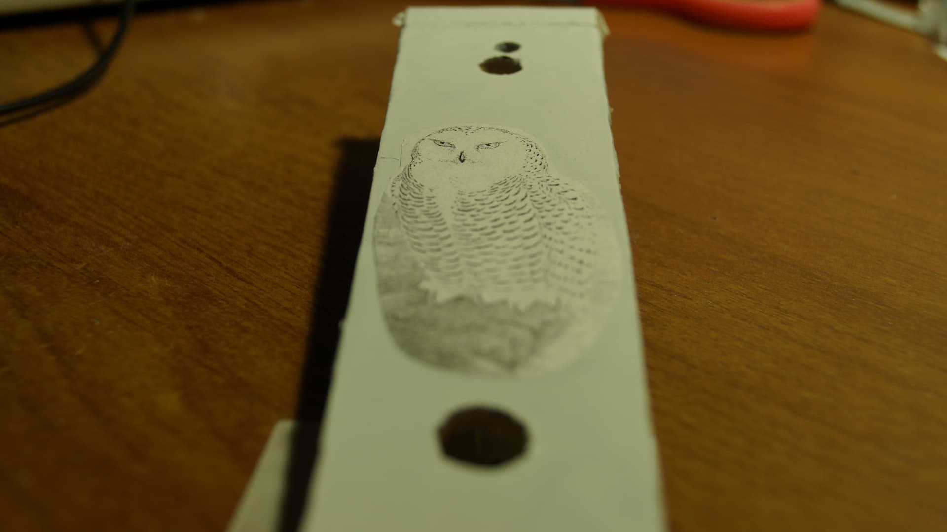
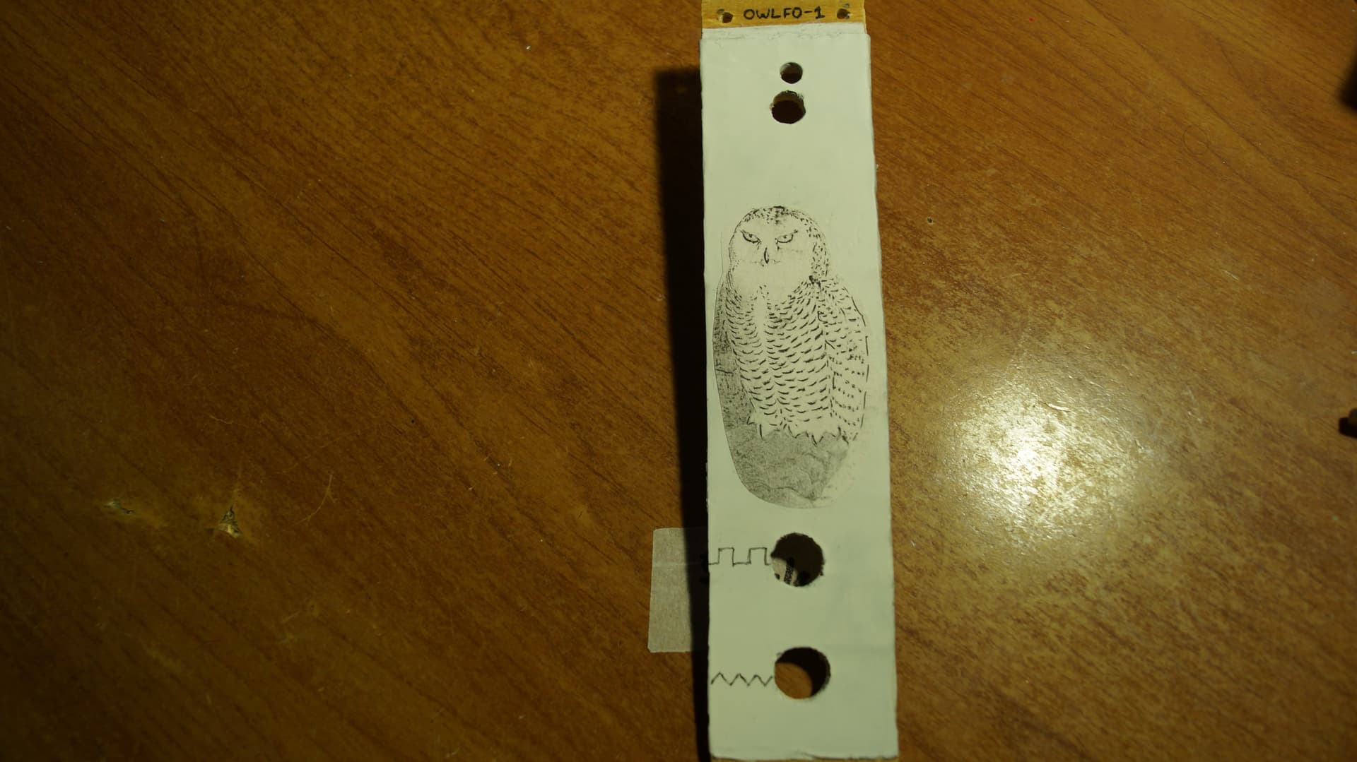
After painting it I was a bit unhappy about how boring it looked and painted some straight lines with the black acrylic paint. It didn’t go well… So I had to hide my painting mistakes, and my best though was to use a picture that I downloaded from the internet. But it would be kinda lame to just glue it on the panel, so I decided to somehow transport this picture from paper straight to the acrylic surface. I was stupid, yes. Turns out even slightly hot iron melts the paint (it was only one day after painting) and… this is very dumb, but after seeing how hot iron is not good, I started to think about acetone. And you know what… Who knew that this extremely aggressive solvent would also melt the paint… After all these experiments I had to re-paint the panel twice, first time I sprayed the paint a bit too narrow. Narrowly? I don’t know, english is hard. Anyway, that was the last time I used pant on this panel, but 4 layers of paint is a bit too much for this kind of surface

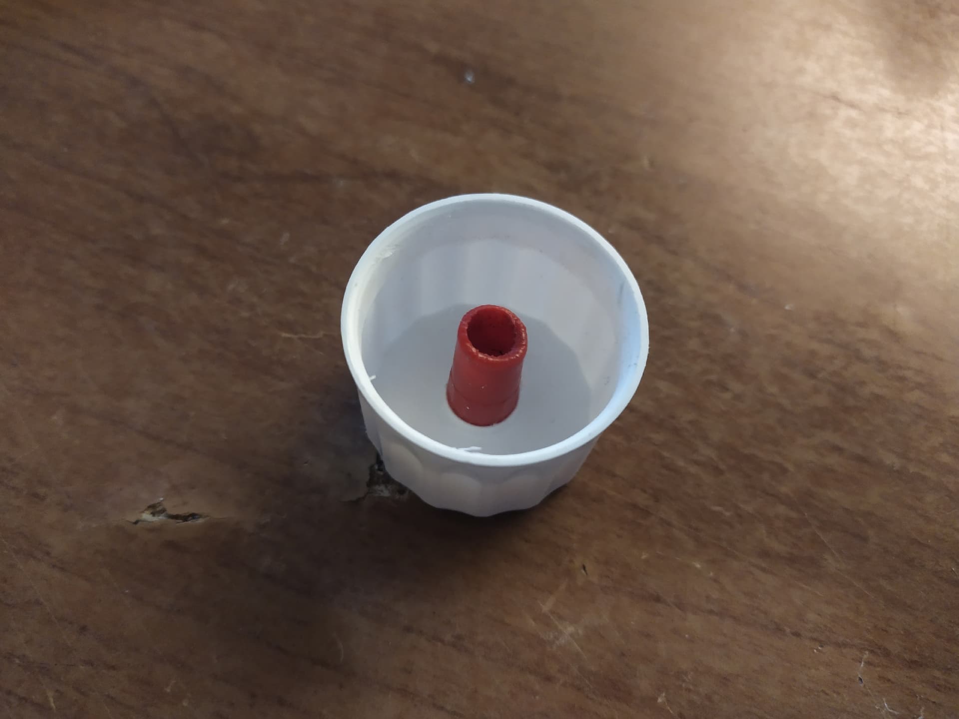
And well, I just couldn’t continue with this thing anymore, so I cut another picture that I downloaded from shutterstock (and you can see that on the photo) and just slapped it right on still wet acrylic. For some reason it didn’t take, after an hout it was still unglued, so I put it in the vise and pressed it onto surface. Now it sits perfect, but everything around it got smooshed and it looks ugly. Alright, I though, next time I should use a lot of rubber. And as I had to glue the scale for the potentiometer, it was a perfect opportunity to check if it works. Well, it kinda works. But at the same time it’s not better than just pressing paper into paint with a wooden stick or something. Also I forgot to check the pieces of rubber that I used and there was something bad on it, some kind of grease… And that’s why it looks like shit! It wasn’t my fault (it was).

Anyway, that was an experimental module. So I am quite happy with the information I got. I am not happy with the result, but it’s better than nothing, I guess. And also who cares! From afar it looks great!

*ah! I forgot to mention that it is based on two very slightly modified schematics: Maritz Klein’s coloured noise (It was a starting point) MFOS Noise Cornucopia (that’s why my module is called Maize, Corn - Maize, I know Cornucopia isn’t about corn. Also noise - maize and bloody maze it turned out to be at some point. And also I was able to get the popcorn sound on the breadboard. I can’t make it with the finished module for some reason. Probably because LEDs are different. Anyway, It’s quite fitting)

3 Likes

Sounds like you are having fun, it’s an addictive journey.

Please keep us updated, your posts are a lot of fun to read.

2 Likes

That’s so right, haha. I am taking some time off though, for now. I just ordered 100pcs of GL5528 for vactrols and I am waiting for the shipping. It was relatively cheap. Few weeks ago I bought an old soviet photoresistor and it was close to 1$, also there’s a number “1970” on its body, I think that was the year when it was made. Imagine that! Probably Jimi Hendrix was alive when this thing reacted to the light first time. And Jim Morrison too! It was 50 years ago… Makes you appreciate the electronic components a lot! Well, if 1970 is indeed a date here.

Haha, thanks! There are lots of typos though. I rarely re-read what I am writing, if it is not for work. SO there are two times when I typed “though” instead of “thought”. Damn. And I don’t want to edit, too lazy for that. Also sometimes I am starting to type something and forget what I wanted to write, so I just go to the next thought, sometimes forgetting to delete the remains of the previous one, haha. So it’s great that despite all of that, you find it fun to read, haha.

What I am thinking right now, btw is a VCA. I don’t know how to match transistors (I guess I have to learn how to do it at some point), so I am thinking about a hack-ish way of creating a VCA. I know Audiophool on his channel made a one transistor one, and maybe I should try it. But before that I want to experiment with the wavefolder. I have a theory that is very stupid, but it could lead to an interesting result despite its daftness. So here’s a pic:

Now if we find a way to voltage control the depth of wavefolding, it would make an interesting sound. It’s not 100% accurate and also it’s not a real VCA, but it’s very simple [I was also thinking about phaser VCA, that would be interesting too, but I think it wouldn’t be this easy to CV the phase shift]. I was playing with this idea in VCV and it was fun. Now I need to go to falstad or something and try it with the circuit simulation. But I am lazy and busy for now, sadly people are not paying me for my stupid ideas, so I have to work, meh

2 Likes

Looks like you have just invented amplitude modulation. Now if you want to voltage control that, it would be common to use an OTA, such as an lm13700. The videos I linked way back at the beginning of the thread cover it, in maybe too much detail.

1 Like

Hahaha. Did I? Well, reinventing the wheel is what I am good at! Well, what I am thinking of is probably based on AM, but sounds different because of folding thing. I guess I could try and think of VCA based on AM purely. Probably it is possible and I guess not too hard… I will do the matched transistor thing later though anyway. No way of avoiding it, sadly. Too many circuits need this stuff

You mean Lanterman’s videos? He has like a ton of them though, haha.

I really want to bulk order this thing, by the way. I was reading an article yesterday with a title something like “CV anything with LM13700”. Don’t remember, it is bookmarked on my phone though

1 Like

A video done by a synth Diyer on transistor matching https://www.youtube.com/watch?v=RpptRXe60yw

Or matched pairs of commonly used 3904 or 3906’s are cheep enough, unless you are planning on macthing loads. Be careful as to where you buy matched pairs from, as not all matches are the same.

Matched Transistor Pairs – Thonk – DIY Synthesizer Kits & Components

1 Like

Thanks! I was trying to find a good video on the topic, but… What I had found wasn’t really good. This one I haven’t seen!

I was thinking about using a schematic by Yusynth (or shared by Yusynth on modwiggler). This method is as simple, I guess! Which is big plus!

Thanks again!

I actually have a couple of old soviet transistor pairs (I think they were made in Latvia and they are still making them)

1 Like

Alright! New thingie. While waiting for the stuff for my Sample and Hold module to arrive (LF398. I rejected the JFET config because of… I’ll tell you later!), I decided to do something easy and Skull&Circuits LFO seemed fairly easy to make. Too easy almost, so to make it a bit more interesting I chose a 20x80mm PCB. I guess it is a place where in a bad story you would expect a phrase “Oh how I was wrong!”. But no, it was a bit challenging to solder, but otherwise everything is fine! No drama. Or almost no drama.

Here’s a schematic for everyone interested. Despite the easiness it took me few days to finish it. I ration my solder fumes inhalations! That and also I have to work and do other stuff. Anyway, by the time when everything was done with electronics side of things, I already had an image in my head how I want it to look. Here’s a sketch:

Nothing fancy! Except the blinking knob. Well, it’s easy to make a knob blink. You just have to put an LED somewhere inside and make this knob transparent. Glue a big toothpaste cap and a ball pen cap together et voila! It looks a bit stupid, but it works and that’s enough for me to be happy with the result.

One thing though - for some reason the LED was pretty dim when I tested it the first time. Whatever! Not a problem for now. Also it behaved erratically. That’s also not a problem! For now anyway!

Or is it a problem? Well, it turns out, it is. I plugged everything in and checked the output with my guitar combo. The frequency response was very strange. It was exponential to some point, maybe 0 to 5% and then it stayed there for the rest 95% of the knob movement. It looked like there was a problem with a capacitor. And yep, I forgot to bridge one of the cap leads to the op amp. Stupid! Anyway, now it works fine or almost fine, because rate is not stable at all and triangle output is a bit noisy. I am not sure what could be the problem there. I traced the triangle output and everything seems normal. Could be my PSU really. We’ll see later!

Next step is, obviously a front panel. And this time there was almost no problems! I think I am learning. I hope I am. This time started with a piece of plywood as is. Cut it, drill it, measure the wires for the front panel elements, re-solder the wires, attach everything, check if there are any problems, proceed to the design section. Fast and easy!

On the second pic, where everything is disassembled, you can see my genius idea how to attach the PCB to the front panel: ball pen again! Now it’s the stem or whatever you call it. You can even see the ink! A very good quality product.

Alright! The design section. This one for some reason ended up with the Owl picture by John Gould on the front panel. Why? I have no idea. It just happened. Also I forgot to take a photo of a front panel before it got painted. Oh well

Looks very cool! It’d be a shame if someone destroyed it with a gel pen and no artistic ability! Even though there was a reason: the pic was too bleak and I thought that after the coating, there would be even less contrast. Good intentions, yeah

After two layers of lac:

Well, it’s not too bad! Looks fine, I guess.

Backside:

At this moment I assembled everything together for the last test and realized that LED shouldn’t be this dim. I checked the schematic and measured the resistor just in case if I put 100k instead of 1k. But nope. The reason is much simpler: I forgot to bridge the LED positive lead to the +12v. Yes, it happened again! (it is a bit concerning, because it shouldn’t work at all… I think. Then who was phone???)

And here we are! A couple of last touches (hot glue) and the final result:

It still works a bit erratically. And I still don’t know what the problem could be. Well, It could be that I forgot to solder something together yet again! Or it’s my PSU. Or that’s just how it works… I don’t know. And for now I don’t really care.

Now I have to go and take my LF398, finally. I wonder what kind of picture on the panel it would end up with. Place your bets

2 Likes

Nice, you do seem to be having fun with DIY stuff. One of the nice things is you get to be as creative as you wish with the design and you have a flair for design. If we have homemade illuminated knobs on your first module, I can’t wait to see what’s next.

The LF398, it’s fun, I’ve built a couple of circuits with these, always have lots of droop on the output, you may have seen people talking about capacitor types, they do really matter here. Don’t expect to hold V/Oct for too long…

Oh, my bets for a picture, a centipede riding a unicycle

1 Like

Hahaha! Well, it’s the second one! The first one was my take on Noise Cornucopia by MFOS. I just like the noisy stuff. I cut off everything except for Grainy Noise and White Noise though…

Yeaah… I wonder if there is a way to kinda counter that. I was thinking about ideal program-like way of doing that and it seems easy, but in real world it would be very complicated, I guess… My idea was to compare two states of a signal and if there’s a droop, to negate it with some kind of magic circuitry. There’s probably no way of doing that without making the droop steeper and also the second half of this magic thingy would be overly complicated, so I guess I have to accept the droop. Cause I want to use my fancy polystyrene 1n cap that I took from my old (and sadly broken) Sharp CD-S400 CD/cassette system.

Hahaha. We’ll see!

The interwebs is full of just this discussion. In short, two answers keep occuring, place a quantizer after an analog sample and hold, or just do it digitally with a micro controller. I use both, as the analog has more character.

1 Like

I was thinking about quantizers too. But I thought it’s not a solution, cause after some time the note would drop 1 semitone down and you’ll get the quantized droop… If I understand it correctly. I guess the true analog way would be to chain few S&Hs together and make some kind of delayed trigger thing. The good thing is that the second S&H could have a bigger capacitor, cause there’s no need for a precise timing. Well, that’s what I think without testing anything, haha

But I was thinking about a quantizer anyway. I like quantized stuff. In VCV I rarely do melodies without quantizers. Sometimes I do the chords without quantizers though. It just feels more rich and you just go with what you feel like doing. It could be some fancy chord that you wouldn’t come up with when using quantizers (in a diatonic mode anyway). So yeah, I will probably make a quantizer later anyway! So maybe I don’t need anything to negate the droop for now. Laziness - 1, Me - 0.

1 Like