DIY Module Front panels (two questions and a big tangent)

I also wanted to know this, I had been doing it in the digital domain, but never analogue. I came across this series of videos, that explain a lot, and also analyse some of the classic synths.

Warning: I watched these and now have a 1.2m X 1.2m rack of Diy modules in my lounge

2 Likes

Hahaha, that’s actually promising!

Thanks!

1 Like

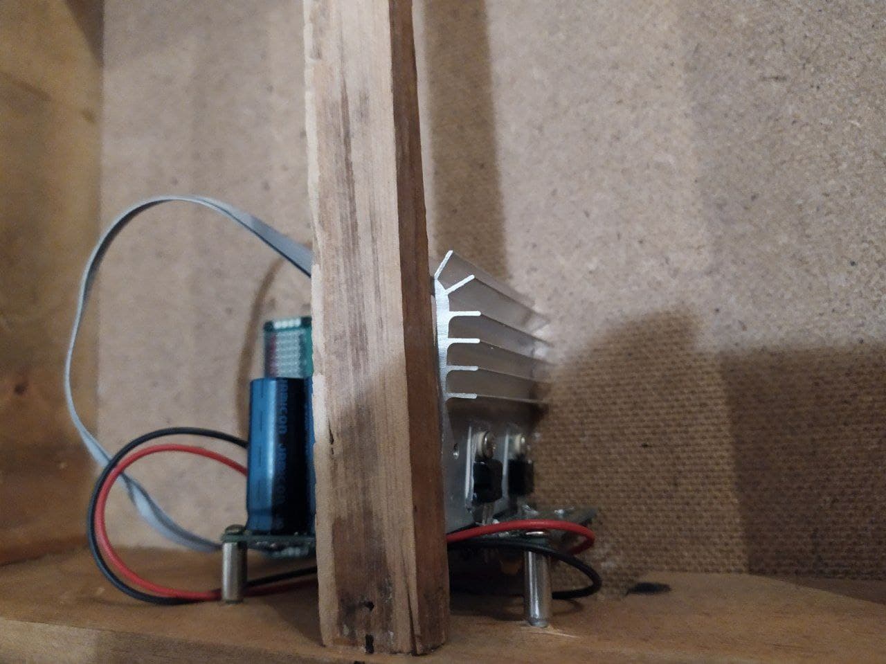
A little update. It took me a week to make a case. I hate woodwork… Just to compare: PSU took me two nights and it works fine, although I think it’s a little usafe. I will redo it if there would be problems. PSU is based and, well, copied basically from Mateusz Kranz (I mean, Moritz Klein) schematic. I know there are better solutions, but I just decided to go with this one.

I made it for kinda custom sized panels, so there’s no need to be precise with 3U, 4U or whatever. It is close to 4U though. I think 4U is about 177mm and the space between panels in my case is 34cm which is, when divided, gives me 170mm. So close enough.

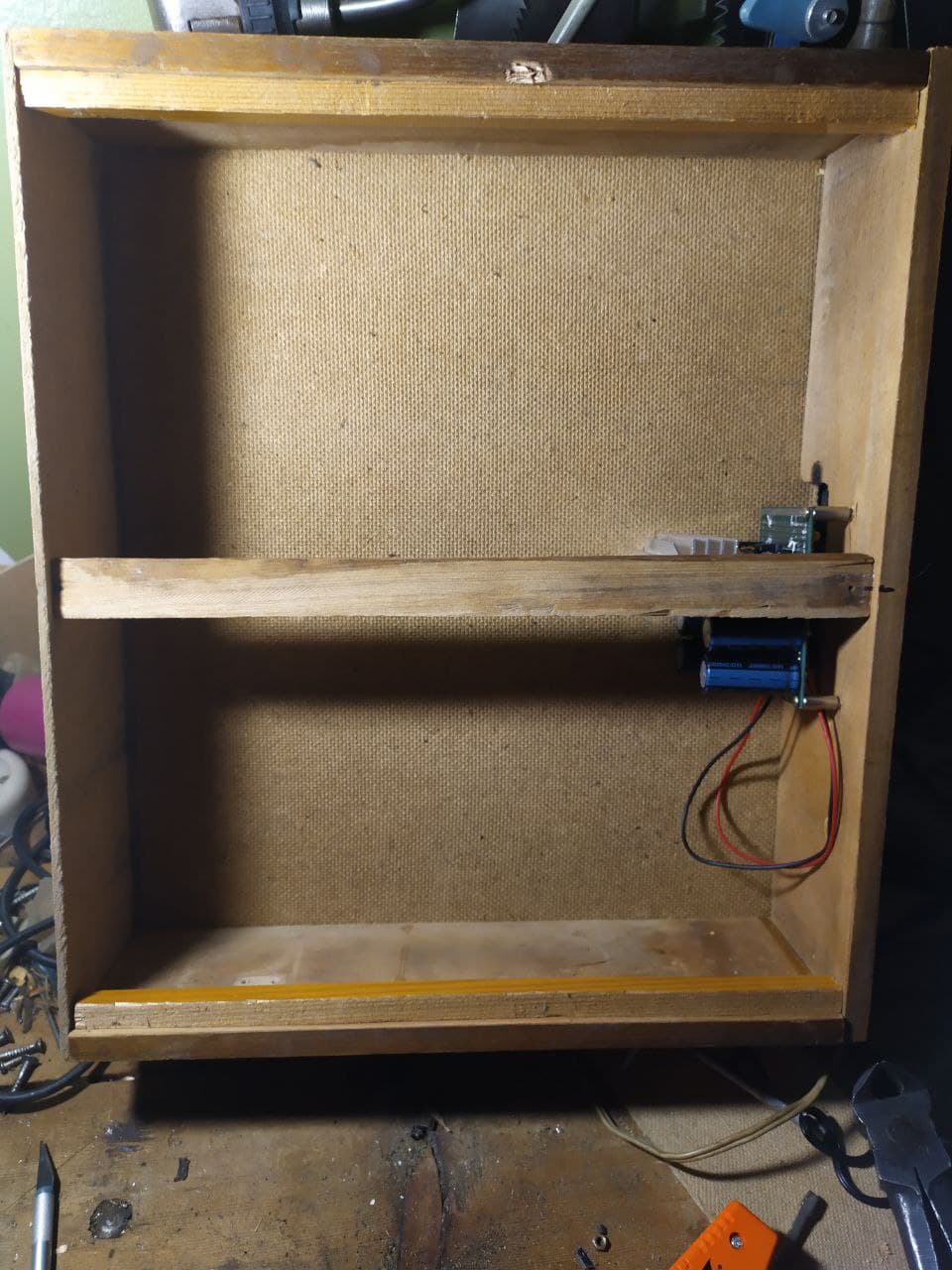
I don’t know if hanging PSU like that is a good idea, but we’ll find out! I did it to maximise the useful space in my case. As it hides behind the middle shelf\rail\whatever, it gives me a lot of free volume to work with. I decided to face the heatsink up, cause everybody knows that heat goes upwards and i am concerned about all of my capacitors, I don’t want to cook them like you do with a grill chicken or something.

Next step would be the power distribution line.I think I will do it on demand though, so one pinheader should be fine for now as I have three modules planned, one of which has been on my breadboard for a week or so, so it’s almost ready (it is ready as is, but…)… It is a noise module that I will show in the next update, I think. It is also based on Mateusz’s video, but I want to make some changes before transporting it to PCB. Like adding LEDs for the outputs and transporting it to TL072 as I don’t really need a blue noise output.

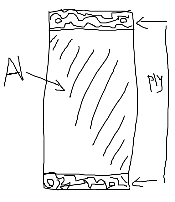
For the front panels I decided to use plywood with some aluminium foil or a beer can wrapped around the middle of it (and probably painted white, maybe black, or maybe I would just leave the metallic shine). It should look like this:

Good thing I have a piece of plywood that is a bit larger than 17cm in height and maybe 60cm long. A lot of material to experiment with. I imagine the plain plywood would look like ass in this kind of casing, which is also wood. I am not very fond of all wood electronic stuff. Not because of the fire hazard, it just looks wrong to me. I could paint it, but the texture would be weird and… the whole thing is splinter-inducing, I don’t want to add some extra splinter-friendly stuff. So I want to try aluminium while maintaining the wooden look, hopefully it would be not extremely bad.

And that’s all for now! I will show you some new updates in the future, maybe when the first module with a panel would be done. Then maybe I will show you a couple of other modules and leave this thread for internet archeologists in the 25th century

1 Like

If you are concerned about heat, you could always drill some holes at the top and the bottom of the back panel and convection would help dissipate the heat, as long as you do not overload the power supply.

For my very similar PAIA rack from many years ago, I left the back panel off entirely.

1 Like

Not really… Not now anyway. My 12vAC source is a actually a transformer (i need a case for it…) that provides about 500mA and something fairly close to 12v if I remember correctly. So I don’t think voltage regulators would be a problem for now. As I understand, 7x12 regulators heat like crazy when the current is high and\or voltage that they need to regulate is much higher than 12v (well, I say “much”, but extra 3v probably would grill my caps and maybe the regulators too…). I might be wrong. Maybe they heat when there are fluctuations in voltage or current… I don’t remember, I was reading it a week ago and back than I though “Oh well, it looks like I am okay for now”.

Anyway, I’ll update the transformer later to 1A or I’ll buy the wall wart (it is surprisingly hard to find 12vAC one for some reason) AND THEEEEN heat would might become a problem, hahaha (well, given that I would draw 1A or more from the PSU, which is… doubtful or wall wart would be like 15v instead of 12v, which is more realistic, cause a lot of stuff they sell here is untested and just goes from the chinese factory to the stores in my city)

Oh! Haha, I never thought it might look like PAIA, but now that I think about it, it does!

Alrighty, so here’s where I am now with modules power cables situation. I knew I have to use pin headers, so I decided to enforce the connection of the wires to the base by glueing a piece of rubber (taken from my old bicycle tires). If anyone wants to repeat this experiment - don’t. At least, not like I am doing it. So here are the pics, here we go

I was kinda happy yesterday when I made the first one. Today though when I was making the other one, I decided to go with a smaller piece of rubber, which is fine with this kind of thing. BUT I suddenly encountered two issues:

  1. Pins are moving like crazy

And that’s the good side. The today’s side is even less aligned, it’s very wavy.

  1. When fixing the rubber with the wires I was (and am) using two sets of vise.

The smaller ones I also use to solder stuff, so while it is fixing (right now), I can’t do anything except for playing with VCV and writing posts on this forum (and waiting for the work stuff). Anyway, when fixing pin headers there you could be unpleasantly surprised when checking the continuity. It seems like rubber+glue+vise is not the best combination for the small wires. They just pop out from the pin headers or break or… Something. So I had to redo the “good” one today. And redo the “bad” one again. It’s very stupid.

So for now I have two ideas:

a) use rubber on the other side of pin headers, it would leave much less length of a pin to solder stuff to, but the problem with misaligning should be solved. Also It might help with fixing the glueing parts together.

b) maybe trying the thermosetting for each wire. I am not sure if it would hold the whole set of pins as the force that is being applied can’t be equal to all the pins.

image

physics sucks

It might work like this though. The pyramid style, fixing each wire to the pin, then fixing 2\3 and 4\5 together, which should equalize the force between them four and then fixing them with 1 and 6:

image

It looks stupid and I am not doing it. Maybe I should use duct tape or maybe superglue with some kind of fabric… I am unsure yet

Been there and done that many times in the past when building my own electro-mechanical components from scratch or drastically modifying what I had. Sometimes the third time is the charm :wink:

1 Like

But it is the law! :wink:

3 Likes

One little update, one little delay and one little fml moment

So after making my first power cable I decided to check it with PSU. I was very surprised when it showed me these results: +12pin to ground = 12, as expected. -12v to ground - 0. After turning off the power and waiting for 5 minutes for the capacitors to discharge (“Wanna know how I got these scars?”) I checked the -12 route to check if it was shorted to ground. And it was. Before mounting it into my case I checked everything for any problems and there wasn’t any. So Whatever happened, it happened after I checked the PSU (it wasn’t in its final form though - a hint) and before I mounted it into my case. Or while fixing, that could be too. Anyway, I know what the problem is and I fixed it already. So here’s a little game: look at this picture and guess what the problem was and how I fixed it!

I delayed the building of noise module again, because I was thinking about making a… what I was thinking should be called “random clicks noise”, I had a schematic in my head, using TL074 as a comparator, but couldn’t make it work for some reason (because I’m daft maybe), so I googled different kinds of noise modules with more than just “coloured” types of noise and found the “Noise Cornucopia” by MFOS. There’s a “Grain noise” that does exactly what I as thinking. So I will add it after figuring out how to add CV input to the grain density. After that I will probably use the other part of Noise Cornucopia, the random gates generator as a separate module. Probably. I don’t know yet.

While searching for the schematics I encountered a weird problem: some of the pages wouldn’t load, I was thinking that is probably because of how old some of them are (early 2000s sometimes), but later I discovered that when using VPN, I can see most of the pictures. Turns out, it is a fence against russian users, some kind of idiotic political BS with a pretense that russians could use these schematics to build something destructive. Oh yes, the nuclear synthesizer! The dream device was almost in my hands, if only I knew how to use VPNs! And that’s the thing. Any kind of VPN can easily fool this kind of “internet fence”. If a person is smart enough to make a dangerous thing, these kind of obstacles are nothing to them. Why is it there? Just to annoy normal people, I guess. Well, I am not saying anything against site owners, most likely it is an order pushed from above, some kind of law. First time I encountered it when checking the instruo website for manuals for the new modules.

get tae f

That’s all for now! A cheerful ending, I know

2 Likes

Voltage regulator case shorting to heat sink?

2 Likes

My guess is the two voltage regulators mounted on the same heat sink were the issue. How you fixed it, well I am hoping by using separate heatsinks.

I prefer to use the 12vac wall warts to power my psu’s, much safer.

1 Like

Exactly! It was very stupid, I know…

1 Like

Yep! You are both right. I guess, the voltage regulator case is connected to the middle pin… So 7812 is fine, the middle pin is ground. But in 7912 case, it’s input. So i was basically bypassing the voltage regulator by sending the negative input voltage to ground…

It is… Burt I decided to make it to practice a bit before doing the actual modules… cause i mostly did the fixing before, just changing caps and broken wires and all that stuff.

Well, sadly no. I don’t have two separate heatsinks of that size. So I just isolated both of the bases with some special piece of rubber… You know the type. Like what you see in the computer PSU. You can see it on the picture (pic was taken post-fix)

1 Like

Does that not defeat the purpose of the heatsink?

1 Like

I guess it doesn’t… At least I hope so. My best guess is that it is some kind of heat-conductive rubber as they use it on PC PSUs and it actually works fine… Well, we’ll see

*I actually smeared a healthy dose of thermal paste on both sides of these (hopefully) heat-conductive rubber rectangles. We’ll see if it was a good idea too…

Back in my days, they made those out of thin mica.

I guess I saw this in old soviet stuff too. Like my old soldering iron. I tried to repair it few years ago and it was a bad idea, because when I pried it open, using a reasonable amount of force, the huge cloud of mica dust and… just dust, I guess, appeared and made me a Micaman, I guess. There’s no superpowers though, so I think I missed one or two steps in that direction… Anyway, all the mica broke or got broken and made the soldering iron unfixable. I guess it was mica. Because it was resistant to high temperatures, dielectric and… it looked like mica

Thermal Conductivity

Mica: typ 0.5 W/mK (source)
3M Thermally conductive silicone pad: 5 W/mK (source)

The right “rubber” conducts 10x better than mica.

2 Likes

Ok, but the thermal resistance of the mica was not usually super significant compared to the heatsink.

edited, added Thermal Conductivity

(The thermal conductivity of aluminum and its alloys, is 88 to 251 W/m*K)
(Atmospheric air has a thermal conductivity of about 0.024W/mK)