I think that’s a good idea anyway. But even better to keep it at 4hp, probably
But i also like the idea with the MIX 4 expander, i think it would make that set pretty complete and an equally solid choice for all types of mixing tasks…
Don’t know… I like both ideas, the MIX 4 solution might save even more space altogether, because most of the time you probably don’t need the modulation, but could conveniently add it without changing mixers, the Bandana just has all the options already laid out and is still small enough to be used everywhere…
I say do both or one of them, or none… saving Bandana for the library in mono just as it is would be good, too, i think.
I just had another thought - maybe the input for VCA CV could be normalled, too, giving the option to do attenuvertion and offset in one channel.
A bit excessive maybe, but could save another little bit of space here and there.
The layout looks really good, more structured, easier to read.
Maybe the LED’s could still fit above the IN and OUT ports… but no LED’s is fine, too, I guess, they tend to be distracting from the easier to read knobs.
Yeah, I thought of that as well. But the core function of the CV circuit would then change. When patched it adds to the Level to establish the total attenuation. When not patched it is added to the input instead as an offset. I think that is too confusing.
Using the original design you can attenuate and offset a signal using two of the clusters with only one output, one without an input for the offset, and the other with an input for the attenuation. So just like with the original, it can be a dual attenuator with offset.
Yes, and for me the biggest issue is dealing with polyphony. There isn’t any good way to indicate the level of all channels, so I decided to eliminate the LEDs entirely.
I barely tested, so I wouldn’t be shocked if there are significant bugs. But the code design should be solid, so bugs shouldn’t be hard to squash.
With the default configuration, I believe it should behave exactly like the Audible Instruments version, which in turn mimics the Mutable Instruments Blinds except the outputs are not limited to 10V.
With the Clipping option you should be able to better approximate the Blinds behavior.
Oh yeah, I haven’t yet configured the bypass behavior. Right now all outputs are 0V when bypassed. I haven’t thought about what it should be.
I’m checking it out a bit now, for now in mono, seems to work fine.
I thought the positions of the level knobs and VCA CV inputs in the panel layout were flipped… would like it better if the level knob would be a slightly bigger knob in the middle, and the level cv a (maybe slightly smaller looking) input on the top left. (maybe without the outer ring)
The attention kind of flows to the middle and i think it would look cleaner and easier on the eyes that way… the little lines to the vca knobs look nice and would help read both values more comfortably, i think, if that makes sense…
Maybe a bit late to criticize the layout, but i liked it better the way i thought it was when looking at the red dots. It looks good, but it kind of forces the eyes into a zig-zag-pattern to read it, and usually the first view goes to the middle. Think it would “feel better” the other way. to me at least.
Doesn’t really matter, just a small thought on the layout, looks great and works great so far!
About Bypass: I think 0V on outputs is the best solution, just checked and it’s the same way the VCV VCA Mix behaves when bypassed… never bypassed a mixer before, but makes the most sense.
When modulating and transposing a poly pitch cv with mono signals, polyphony works as expected.
Modulating a poly audio signal with a poly modulation signal does not work as expected, though… poly mod signals seem to get summed to a mono modulation signal.
No plans at the moment. I think I could come up with a stereo design in 7hp. But I want to move on for now.
Ugh - I didn’t read the Blinds manual closely enough, or think hard enough about the math.
Each channel can already function as a signal attenuverter with offset. Patch the signal into the Level CV and the Level CV Amount becomes the attenuverter. Leave the Input unpatched, so it normalizes to 5V, and the Level knob becomes the offset. The original Blinds design really is cool!
That is not my experience at all. Modulating poly with poly is working perfectly for me.
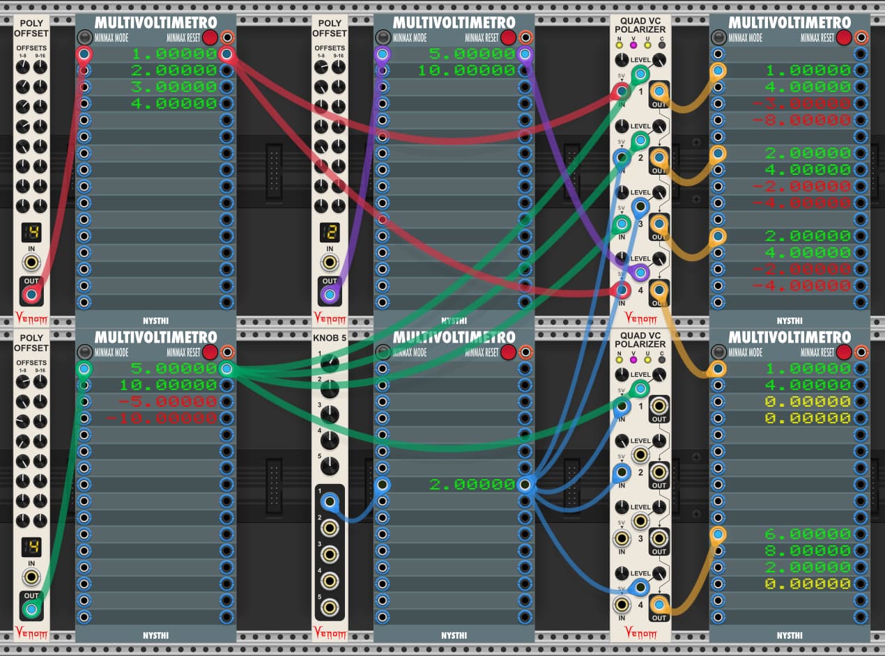
For any given output, the channel count is equal to the maximum channel count found across all inputs that feed that output.
Mono inputs are replicated to match the output channel count.
Poly inputs with the same number of channels work as you would expect.
Poly inputs with fewer channels get constant 0V for the missing channels.
Check out the demo below - all the outputs match expectations based on the math
MI Blinds is one of my desert island eurorack modules in my actual rack. Lots of cool things you can do with it. Your compact poly version is very welcome! Does your design also have antialiasing for ring modulation? I’m guessing yes, since you’ve put it in so many of your other modules.
Chainable VCA Mix is also very nicely done. It’s tough to decide what features you want vs how large to make the module… I agree it’s a sleek form factor you’ve made.
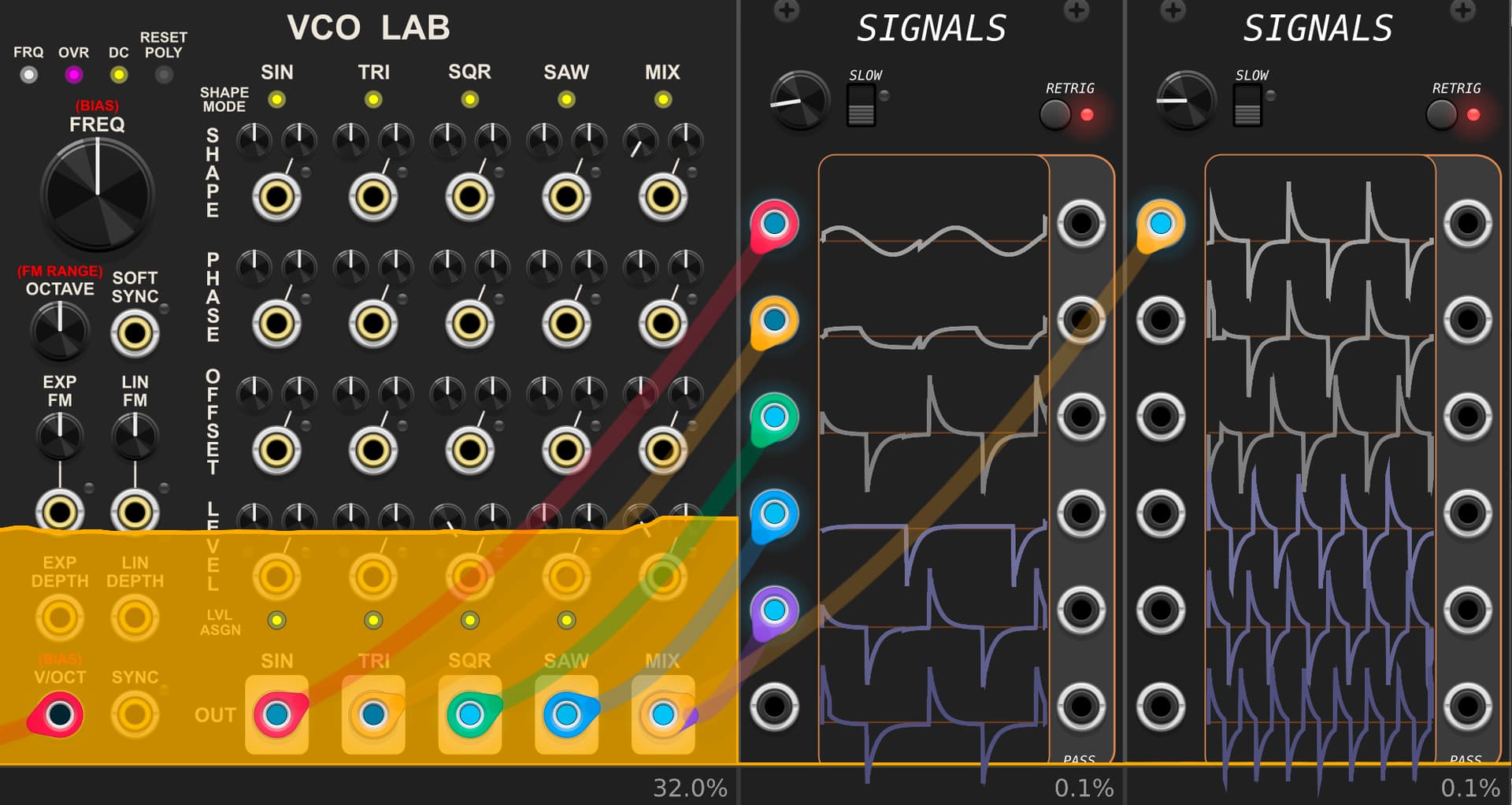
In your VCA Lab I noticed something funny when the DC blocker is on and oversampling is used:
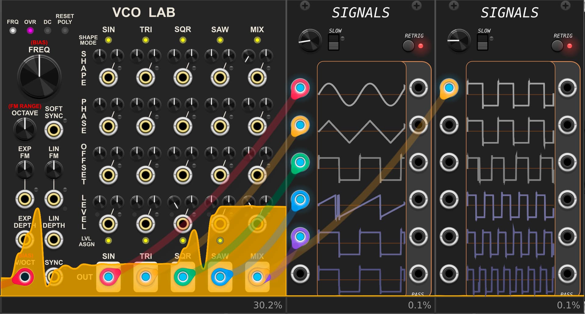
Here is the thing with32x oversampling but no DC high pass:
So, normally oversampling will add those little horns to the square wave since the higher harmonics are chopped. But adding the DC filtering shouldn’t change the waveform so dramatically between the different oversampling rates, I think it could be a bug where the DC high pass filter is not scaling properly as the oversample rate is increased.
Anyways, it’s a cool module, and I’m not likely to use it at 32X oversampling since my computer is clearly not strong enough… the DC filter looks totally normal at 4X.
The only oversampling I do in my compact Blinds is x4 for soft clipping (tanh saturation), which is a non-linear transformation. The final output is upsampled before the saturation, then downsampled afterwards. From what I remember, ring modulation doesn’t require oversampling as long as the response is linear (simple multiplication). I will reconsider my choices if I am wrong about that.
Regarding the unfortunate behavior of my DC offset removal - I talk about that in the Venom documentation
At some. point I want to figure out what is wrong with my code so I can implement proper DC offset removal. I am 99% sure the problem is in totally unrelated code having nothing to do with offset removal, which is a scary thought. The problem is not platform specific. For example, for some people on Windows, the proper code works perfectly fine, and for others, the same binary kills all output from the module. I use the same code for multiple modules, and all behave the same :(. I am thinking I have a bad pointer or uninitialized variable somewhere, and it is sort of luck of the draw as to whether it has a negative impact or not. Like I said, a scary thought.
I tried replacing the algo with totally different code, and they all failed for some people. The only thing that worked consistently is what I have currently implemented in the released code. The worst part is it never fails on my Windows or M1 mac - I get reports from others on those platforms (plus linux) where it fails for them. So I am going to need help tracking this one down. I have kept my head in the sand for a while. After this next release I think I should pause and somehow resolve the problem.
So, if you have two frequencies in your signals that sum to above the nyquist frequency you can get aliasing with a bipolar VCA. This is because ring modulation creates sidebands that are the sum and difference of the input frequencies.
For example, if your sample rate is 48khz, then the nyquist will be half that: 24khz. Then if you multiply a 14khz and 12khz sine signal, you’ll create a sidebands of 14-12=2khz and 14+12=26khz, where the 26khz sideband will alias. But 12-14khz is fairly high frequency if you are just multiplying sine waves. However, if your signals are square waves that contain higher harmonics (assuming you’ve filtered to remove >24khz harmonics), then those harmonics will sum and create higher frequency side bands that alias.
Re: VCO Lab. Okay cool you are already aware of the issue. Sorry to point it out again, I didn’t know. I wish I could help but your predicament with different platforms is not an easy one… I would think you could just apply the DC high pass filtering at the last stage after the other antialiasing is applied, and then it would be unaffected by the sampling rate. But I’m not sure how the architecture of this VCO is internally.
Doh! I knew that. Yes, I should/will add an oversample option to the compact poly Blinds module.
For the VCOs, etc. I do apply the DC offset removal at the end of the chain. But the high pass filter should be “tuned” for the sample rate and/or over sample rate. That is the problem with my current implementation - it doesn’t make any adjustments for either. It is a very simple problem, but something in my code else where is interfering with me making the adjustment.
In VCO Unit the linear FM intensity seems to get halfed with each step of oversampling. So linear FM in 4x oversampling is twice as strong as in 8x, for example.
not sure if it’s factor 2… its somewhat less with more oversampling.
Thanks for that report. I took a look, and it is not restricted to VCO Unit. It also happens with VCO Lab.
That doesn’t seem right, but I’m not sure yet what is going on, or how to fix it.
EDIT - Strike that.
It is the damn DC offset removal that is enabled by default on the Lin FM input. As I talked about in an earlier post, it is naive and does not compensate for changes in sample rate or oversampling.
I really need to figure out the bug that is preventing me from fixing the DC offset removal.
Even linear FM can sound harsh if there is DC offset on the CV input, which is why I remove the DC offset by default. If the linear FM CV is a nice bipolar sine or triangle, then you can use the port context menu to activate DC coupling (remove the DC offset removal), and the sample rate/oversample rate no longer impacts the FM amount, yet you still get sweet FM.
I will update the manual to point out the issue with the linear FM with the current DC offset removal implementation.