So I recently got more modules to go with my SV-1b (two of them being the ES-3 and the ES-6). The ES-3 sounds great coming back through the hardware, but for some reason I have issues with the ES-6. While sending regular oscillators work perfectly fine, it begins to get weird when I send CV outputs like Pam’s. I own Pam’s Pro Workout, Maths, and a VCA as well and when I send a normal CV signal through, it almost adds a pitch bend to it. The best way I can describe it is that if it is a CV signal, then the ES-6 almost interprets the digital version to have a decay/tail to the voltage, even though the ES-6 hardware seems to be reading normal (which is why I think it may be a VCV rack issue). I even tried the LFO that is a part of the SV-1b and it does the same thing. Even if its a square LFO signal.
What makes this issue so much more frustrating is the fact that there is no one else with this issue all over the internet. I have been looking on different forms and I just had to make one myself. Hopefully some out their knows a solution.
I’m not sure I fully understand, can you describe an example signal flow?
You have CV originating with the Pam’s Pro, and that’s going to the ES-6 and then what?
Is the issue that the CV input of the ES-6 is adding a small offset to your CV input? That is normal. But if it’s something else, maybe some more details might help with the troubleshooting.
What ADAT Lightpipe interface do you connect them (ES-3 and ES-6) to ?
Are you on linux, mac or windows ?
HAve you checked the CV levels by other means (multimeter / oscilloscope) if they are too hot (less than -10V or more than 10V) ES-6 will clip.
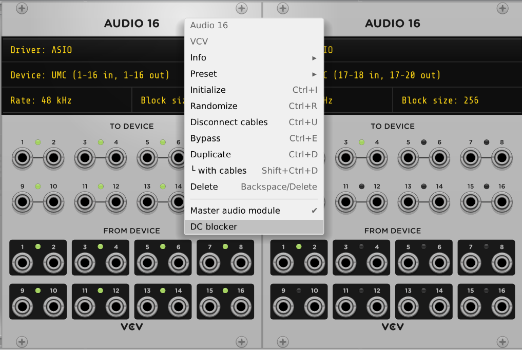
Aslo, have you tried turning off “DC blocker” on the audio module going to your ADAT’s
I’m not sure if it works on both input and output, but try changing the setting for each of the audio modules connected to you IO devices.
Ohhh, yeah, Jens, it does sound like there’s a DC block happening, now I understand what he means by a pitch bend. and a ‘tail’. That fits.
1 Like
After looking at the source, with my entry level skills, I say there’s only DC filtering on the inputs.
the outputs are not filtered by the Audio module.
1 Like
The previous was an elaboration on my earlier post, not related to your post @demcanulty
1 Like
That would also make sense, I think you’re right.
If we could see a scope shot of maybe an input clock signal, that would be informative.
And maybe if we knew what the ES-6 was being sent into.
Ah, here we go, I think I’ve found the answer:
" Jumpers (ES-6 mk3 only)
The ES-6 mk3 has a header on the board labelled GT4. Fitting jumpers on the pairs of pins indicated enables DC blocking on the respective input channels. Removing the jumper disables DC blocking on that input pair, allowing the inputs to be used for CV.
From the factory, all three jumpers are fitted (DC blocking enabled), which is the most appropriate setup for audio use."
zacthorneedm, be sure to remove those DC blocking jumpers, they’re installed by default, so you’ll want to take them off.
4 Likes
Good find.
I have the ES-3. I didn’t read the docs for the ES-6.
I have used [multimeter → serial → OSC → VCV] when I wanted to get external DC into rack.
I used to run an ES-3, ES-6, and ES-8, and I recently consolidated to just an ES-9, and for the first night, I remember being quite surprised by the default settings, including DC blocking. I think it took me until the next evening to wrap my head around all the settings.
With my older ES-3+6+8 setup, I never had to modify settings or anything. I guess they got more advanced as he went along 
But, man, those LED lit jacks on the new models are soo cool and informative.
1 Like
First off thank you both you and @Jens.Peter.Nielsen for being so quick to respond (I’m sorry I am late to the party. I didn’t expect replies so fast). I went ahead and grabbed some recordings and I will try to describe the missing details as well as things I have tried.
To answer your initial question, the signal flow goes Pam’s Random Quantized CV Out → Input ES-6, it then goes to ADAT to Focusrite 18i20 3rd Gen → VCV Audio ASIO, then from VCV it goes signal out → Oscilloscope In, Oscilloscope Out → V/OCT, then finally Oscillator to Speaker out. I have a basic video to help show what’s going on.
https://youtu.be/qptrdtO7ncs
Pam’s and the ES-6 are the only two external modules that are involved in this example.
To answer the questions that @Jens.Peter.Nielsen had, I am going to my Scarlett 18i20 3rd Gen. they are plugged into the 1-8 ports allowing 44.1kz so I have access to all the ins and outs of the ES-3 and 6. I am using Windows 10 and yes I have been using a oscilloscope and they seem to be running below 10V. And unfortunately there was no difference from turning off DC blocker.
I will give removing the DC blocking jumpers a shot and let you know what happens.
Let me know if there is anything else you two need from me and thank you so much for your help!
1 Like
I’m gonna give this more of a test, but this worked so far!!! Thank you again both for your help!!!
1 Like
Felt like I should make an update. The jumpers are the solution. Thank you one more time @demcanulty and @Jens.Peter.Nielsen for your help. I appreciate the immediate responses and I am happy I can actually start doing fun eurorack stuff on a budget.
2 Likes
Hope you have tons of fun! I was just playing with a little hybrid stuff tonight through my es-9, and it broke my creative block that I’d been having trying to work purely in vcv. Sometimes there’s just no replacement for the different parts of the brain that seem to come alive when you’re touching things with your hands.
Glad we were able to help, it was a fun puzzle