Instruo: Modules released

Right, I rewatched the part. He used DC-Coupling for demonstrating the behaviour, but you actually have to AC-couple it, when modulating it with audio-frequencys. Sorry I confused those two settings…

edit: which makes total sense now, because both the negative peak and the positive peak should be equal to reach the same maximum frequency.

Hm… modulating it with anything that has anti-aliasing should not work then, right? Just in theory, I normally don’t use a saw for FM… :stuck_out_tongue:

1 Like

Does a Ratio has any meaning in the context of neonis TZFM? In traditional FM integer ratios are needed to give you harmonics that are related to the harmonic series of the carrier, but TZFM is like waveshaping where the harmonic content is not related to ratios.

Sorry about that.

There’s quite a lot going on in my patch as far as Neóni is concerned, because the connections between the four oscillators are continuously shifting. For this patch/application, toggling the AC/DC coupling does not help.

Maybe not. The original purpose of the patch was to get Neóni to follow the same script as PM modules, and I’m seeing now that’s a fool’s errand.

Here’s a quick run-through of my test patch. Please excuse the weird microphone, as well as my voice. I’m new to narration. Maybe it’s possible that I still don’t have Neóni configured/patched ideally for this situation, but I think I’m just trying to fit a square peg in a round hole here.

Edit: video removed, see post below.

If you start with an initialized Neóni, it outputs C4. When you flip the switch from Traditional to TZ mode, the frequency drops so low that Hot Tuna can’t identify it even in Low Frequency mode.

1 Like

Because 0V at the modulation input is the crossover / phase reversal stage of neoni. The Base Frequency is still C4, but it requires +/- 10V on the modulation input to actually reach it.

Edit: And that is the reason for the different behaviour in your video. Your algoseq (which I never tried, sorry - but now I need it in V2 please :stuck_out_tongue: ) is constantly mutating the carrier and modulators and it seems with the mixing and modulating of the FM-signals there is never a signal hot enough to modulate the carrier to it’s base frequency.

Edit 2: Ok, just checked. It is not related to 10V or +/-5V. The maximum voltage of an audio signal is always the base frequency of neoni. Ehm… nope, no clue then.

1 Like

Well, I’m not a total expert, but what you say sounds “rightish”, and it’s been so long since I made an analog VCO that I totally forgot that they very well might not go “through zero”. The whole linear through zero thing was a holy grail of analog “back in the day”. In digital it all just tends to go through zero, so I hadn’t thought much about it. But, yeah, non-trough zero would probably go out of tune - good point.

(btw, my Voyetra-8 synth was one of the few from back then with analog linear fm, but the depth was limited so that not only did it not go through zero, it didn’t even get very close to zero. So it was in tune but not super dramatic)

I think you may be wrong about the relationship between the carrier and modulator frequency, but maybe it’s a good analogy - I don’t know. Oh, now it can’t be right, because as you increase the modulation depth you get spectral lines above and below the carrier freq. I think the you get frequencies at carrier, carrier + mod, carrier - mod, carrier + 2 * mode, carrier - 2 * mod, etc… all with complex amplitudes that make FM kind of unpredictable, but a cheap way to get a complex dynamic timbre.

As usual I would recommend looking at the output on a spectrum analyzer, although perhaps my brain is just wired that way…

No, it takes +/- 1 V to reach the carrier base frequency (actually ~1.072)


OK, this was all driving me nuts. Regardless what the end sound is, I would like to know what each of the oscillators is doing from a frequency standpoint when applying true FM. And there is not much consistency with the 3 oscillators I looked at in V2 - Neoni, VCV VCO, and Bogaudio VCO.

To investigate, I opted to apply constant voltages into FM input, with attenuation set at 100%

VCV Fundamental VCO, Exponential FM mode:

  • 0V no impact - the frequency remains the same
  • 1V frequency is x2 - 1 octave up
  • 2V frequency is x4 - 2 octaves up
  • -1V frequency is /2 - 1 octave down
  • -2V frequency is /4 - 2 octaves down

Perfect - exactly as I expect. The FM input at 100% attenuation is basically an alternate V/Oct input. To prove it, I also applied an audio rate signal attenuated to say 10%. The sound when patched into the V/Oct input is identical to the sound when patched into the FM input at 100%.

VCV Fundamental VCO, Linear FM mode:

  • 0V - no impact, the frequency remains the same.
  • 1V - frequency increased by ~261.63 Hz.
  • 2V - frequency increased by ~523.26 Hz
  • -1V - frequency is reduced by ~261.63 Hz
  • –2V - frequency is reduced by ~523.26 Hz

So each volt represents 261.63 Hz = C4 If the base frequency is C4, then 1V is up 1 octave, 3V is up 2 octaves. -.5V is down 1 octave, -.75V is down 2 octaves. etc. Importantly, -1V and lower stalls the oscillator at 0 Hz

The Hz per volt remains constant regardless the base frequency. So if the base is C5, then 2V is up 1 octave. 6V is up 2 octaves, -1V is down 1 octave, -1.5V is down 2 octaves, and -2 stalls the oscillator at 0 Hz.

Again, exactly what I expect. It is what I expected before I experimented, except I didn’t know how many Hz 1 volt represented. Now I know.

Bogaudio VCO, Exponential FM mode

Exactly the same as VCV VCO. 0V no change, 1V up 1 octave, 2V up 2 octaves, -1 down 1 octave, etc.

But there is one very important difference. The sound when patching audio rate signal attenuated to 10% into FM at 100% is radically different then what I get when patching into the V/Oct. The FM input is much cleaner, the V/Oct very harsh.

If I use LFO modulation, then the sounds are basically the same, though the spectrogram of the V/Oct is still dirtier.

What on earth is going on here? The only guess I can come up with is the voltage at the FM input is maybe sampled at a higher rate than the voltage at the V/Oct input. So maybe the V/Oct input is introducing some type of aliasing? I tried looking at the code, but I’ve never done any such coding, so I don’t know what I am looking for. I did find the code that uses phase modulation for linear FM though.

Bogaudio VCO, Linear FM

Well, Bogaudio uses phase modulation, so there is nothing to compare. Applying any constant voltage to the FM input has no impact - perfectly understandable. The FM input only has effect when the voltage is varying.
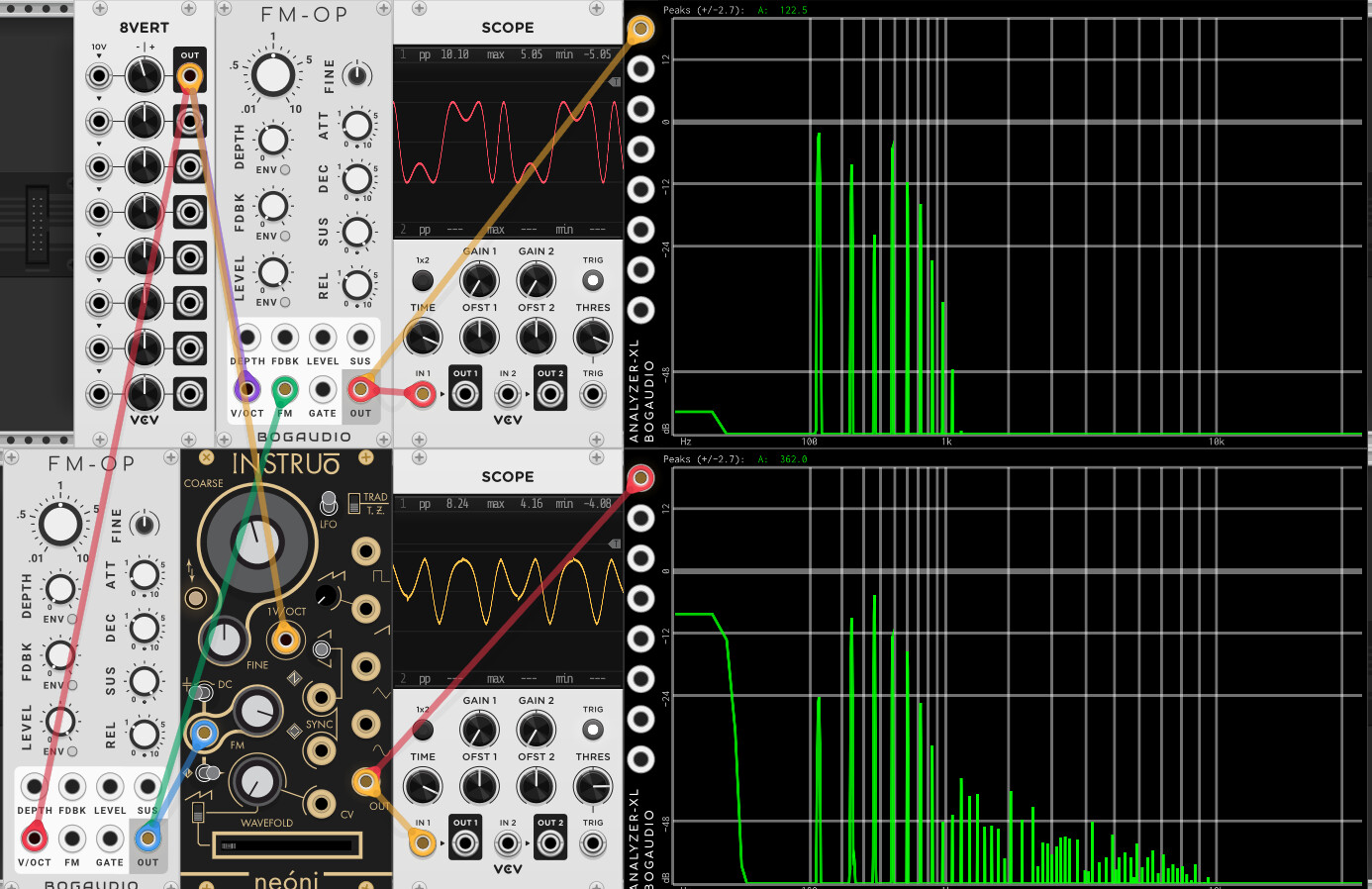
Instruo Neoni

This beast is entirely different! First off, the FM must be in DC coupled mode for a constant voltage to have any effect. That makes sense. But what effect does it have?

Instruo Neoni, Exponential FM

Neoni does not have an exponential FM input. The only way to get exponential FM is to use the V/Oct input.

Instruo Neoni, Linear FM (Traditional) base frequency at C4

First oddity, setting FM attenuation to 1 (100%?) without any input increases a C4 by ~11.3 Hz.

But after actually patching input it gets even weirder - there is nothing traditional that I can see. The formula for frequency is approximated by:

frequency = |Base / 2.1 * (Volts + 2.1)|.

The bars represent absolute value. So the oscillator stalls at -2.1, but not negative values less than that.

The other piece of the puzzle is the waveform is inverted about 0 when the voltage is <= -0.2V. So a saw wave becomes a ramp when negative voltages are involved. (except for the narrow negative range > -0.2)

The number of Hz per volt is not a constant - it depends on the base voltage. So with that formula, regardless of base voltage, -2.1 constant voltage stalls the oscillator. 0V = the base frequency, and -4.2V = base frequency inverted. 4.2 and -6.3 are both one octave up.

Neoni clips incoming FM voltage at +/- 10V, so 8.3V is two octaves up, but you can not get to two octaves up with a negative value.

I don’t see how this can be called traditional, at least from the stand point of how the end result is generated. Maybe the sound is similar to simple linear FM, but I guess you can call this “through -2.1 linear FM”!

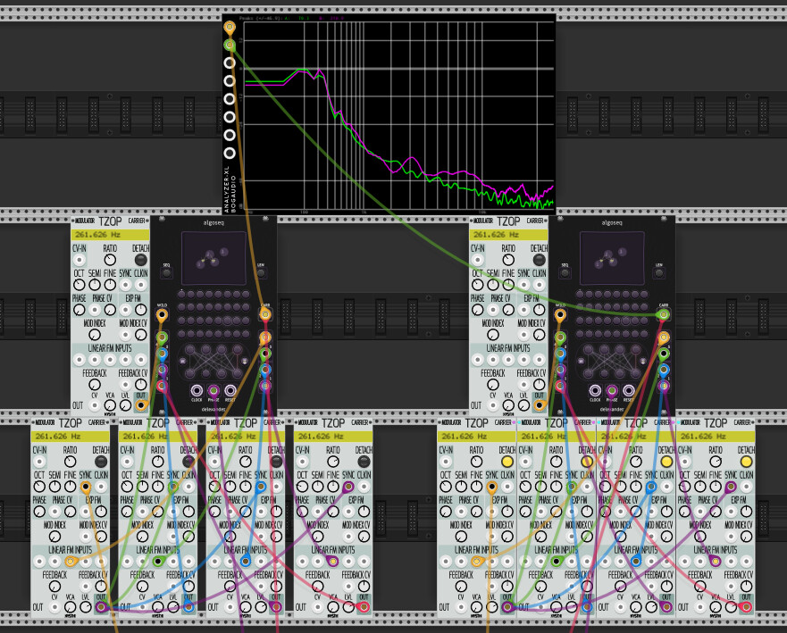
Instruo Neoni, Linear FM (Through zero)

This is very similar to the “traditional” setting, except the stall point is at 0V where one would expect, and the divisor is 1.07 instead of 2.1. The point at which the waveform is inverted remains at -0.2V

So the formula becomes

frequency = |Base * Volts / 1.07|

This formula is symmetric around 0V, so it makes sense the end result is more harmonious.

2 Likes

I took a quick look at this Instruo FM VCO. I really don’t know what it’s doing. If it sounds good - great. It seems to be FM, but then something odd is going on with the output waveform. Possibly intentional, who is to know?

Look at this simple patch. You can see the Bogaudio it putting out "normal’ FM/PM waveforms. The scope looks like I would expect. You can see on the analyzer there are a lot of energy in the harmonics, but then they fall off above 1k.

The other VCO, on the other hand, has a very unusual waveform on the output. You can see it has shap bends in it, and even some small kinks. An on the analyzer there are clearly harmonics going very high in pitch, but at -48 db. About what you might expect from those kinks:

I would encourage anyone who is interested to make a patch like this and compare / contrast the two.

1 Like

Then, if you take the pitch all the way up to 1.5k (very high) then the Instruo starts aliasing a lot, as those high harmonics are now getting folded back. By comparison the Bogaudio is still putting out about the same spectrum as before.

Apart from aliasing, it’s also weird that sine output has harmonics closer to a triangle. At first thought it may be closer to the hardware but this video proofs it’s not the case https://youtu.be/kkAagua3NN4?t=3943

1 Like

I’m going to go out on a limb. without even watching their video. So I am probably wrong.

1 - I think the main thing I’m seeing it that Instruo had a different definition of what “though zero fm” means. It looks like when they cross through zero freq they flip with waveform like a wave folder. That probably sounds great, but it isn’t FM as chowning, yamama, bogaudio, and math would define it. Presumably the analog module does this, and that’s part of what give it its sound.

2 - The funny “blip” on the un-folded peaks is probably a bug in the digital port?

3 - The aliasing at high frequencies is what you would expect with a wavefolder or non-fm VCO that didn’t have any alias mitigation. Assuredly not in the analog module.

I maybe wrong, but the dannysound EN129 TZFM-Oscialltor seems to be very close to the Neoni. And that TZFM-concept dates back to 1981, where it was described in the electronotes No. 129 (hence the name) - http://electronotes.netfirms.com/EN129.pdf

I don’t understand most of the stuff they write there, but the reversal of the Oscillator at 0V and the waveform diagrams looks very similar to what I see on the Neoni. I really recommend watching the video from instruo, starting around 56 mins. in he talks about TZFM.

2 Likes

As far as I know this is how FM actually works in the analog domain. Wasn’t the DX7 PM anyway? It seems as though thru-zero in the traditional analog modular world was a pretty rare thing for a long time. I think there’s something to this flipping thing you mention. I have a Plague of demons from NLC that does this, I believe it is also the way that the old Cyndustries zeroscillator works.

3 Likes

No, anti-aliased modulators work just fine. The anti-aliasing Gibbs effect peaks get incorporated into the resultant waveform, and I imagine color the output, but it remains harmonious.

Well, if you took the time to watch the video, you would know it is intentional. He is very clear that this is a different type of FM.

Again, I think the term “FM” is a real problem. It can mean a particular sound, as what you are expecting, and for most I think that is phase modulation. Or it can mean a technique, which is truly modulating the frequency of the carrier. And even with true frequency modulation there are many variables that can dramatically affect the sound - constant Hz/volt? what value? or scale the ratio by the carrier frequency? Simple non-through-zero? or do some type of reflection/wave inversion to implement through-zero.

Comparing the two can be instructive, but expecting them to be similar doesn’t make much sense. They employ entirely different techniques, and are supposed to be different. In fact, I think it is the very difference that makes it worth taking a look at, and why people may be interested in using the new Neoni oscillator in the first place, whether it be hardware or software.

2 Likes

you are patching wrong TZOPs
when they are “connected”
internally they share all the information about pitch
and only the CARRIER will be responsible for CV in, OCT, FREQ, and FINE freq

only the RATIO knob is separated (to create the correct ratios like on the DX7)

use the DETACH button only if you want inharmonicities that you want not to be related to the tracking picth (wood and metal percussion side frequencies, for example)

1 Like

True, and I didn’t mean to imply there’s anything wrong with this technique. For me (and most people?) “through zero fm” usually means what you are calling “true fm”, and it’s almost always linear (which you call constant Hz/volt).

I think the only disagreement here is whether they “should” call this “through zero FM”. For me it’s confusing, If you like it, that’s fine.

I see! I should have checked before to see whether the two situations below were the same as I incorrectly assumed. They are indeed different:

What do you think about adding a context menu option offering “Full Detachment” so that the modules don’t have to be physically separated (as on the left in this screenshot), or the Detach button could be a tri-state switch with the new 3rd state offering full detachment?

1 Like

I think the operation of Joranalogue’s Generate 3 (G3) eurorack module helped me to understand the two different modes of FM (assuming my understanding is correct). Like the Neoni, the module has what Joran calls a “bias switch” to toggle between what the G3 manual calls “normal linear FM” (what most people are familiar with) and “through-zero FM” (the new thing in Neoni, even though it’s not new because, as Jason mentions in his video, these are ideas published decades ago).

G3 has a bipolar attenuator controlling the depth of FM (knob 3 in the manual). But with no modulator input, the knob is normaled to an internal offset voltage. In this mode of operation, by sweeping the knob from its zero point in the middle (0V offset) to its left- or rightmost points (+/-5V offset), we move the oscillator’s frequency from 0 (stalling the oscillator core) to the fundamental frequency. The crucial point here, it seems, is that the fundamental frequency is attained at 5V.

So what happens when we input a modulator? When the bias switch is down, G3 adds an offset of +5V to the modulator, which corresponds to normal linear FM. As I understand it, oscillators typically go +/-5V, so the offset applied by the bias switch means that when the modulator signal is at its center point (which would traditionally be 0V if it weren’t for the +5V offset), the pitch of G3 is at its fundamental frequency. In other words, under normal linear FM, the modulator moves the frequency above up and down, but the center point is the carrier’s fundamental. (The funny thing with this through-zero terminology is that in normal linear FM mode, if the modulator has lower amplitude than -5V, then we would end up modulating through zero, but nonetheless, this is not what Joranalogue and Instruo are calling “through zero” for these modules.)

“Through-zero FM” on the G3 instead corresponds to having the bias switch up, so that no offset is applied to the modulator. But this means that when the modulator is at its center (zero) point, the carrier (G3), is not at its fundamental frequency. Instead, the fundamental is now attained when the modulator reaches its extremes of +/-5V.

The practical implication of all of this, as others have noted above, and as Jason’s Neoni video makes clear, is that TZFM flips the role of the carrier and modulator relative to normal linear FM. By the way, from the discussion above, this doesn’t have anything to do with analog or digital. It’s only about whether the fundamental frequency is attained when the modulator is at its zero point or at its extremes.

The funny thing is I don’t even think Joran knew if TZFM had any melodic application. I recall this modwiggler post from back in May, where Joran says that TZFM mode “is more suited for percussive and noisy sounds.” That’s true if you try to use it like normal linear FM without understand the carrier-modulator role reversal. Amazingly, the post Joran was responding to actually wrote, “It’s almost as if the modulator signal becomes the carrier and the G3 becomes the modulator - does that make sense?” And it turns out they were exactly right, thanks to Jason’s video that finally explained the right musical application of TZFM.

3 Likes

I have to retract this statement; on further inspection, even when in True FM mode, Terrorform’s pitch is more stable and more closely related to my expected result than Neóni.

I created a separate topic for discussion of that test patch of mine, and I uploaded the patch there too. (This version uses Algomorph Pocket. Algoseq isn’t yet ready for public release.)

I did a big test patch with around 15 Neonis and musical context with all different kind of sounds generated all from neonis without any filters, but it crashes on startup :neutral_face:

I have no problem at all with the pitch tracking of neoni, but I think there is a bug. When you set it to TZFM-Mode and use a sine VCO as pitch-carrier (so in front of the neoni) I have to set it to DC-Mode. In AC-Mode I get a short duration at the start of a note, where the pitch swings in - it is stable after that, but that should not occur right?

This is the key to understand neoni. In addition to this, the input signal has not to reach +/- 5V exactly. There is some math going on to detect the maximums of the incoming waveform and to set that as the base frequency. Maybe just a derivation where switching from positiv to negativ slope is positive maximum and the other way around.

Oh, and welcome to the forum!

1 Like