I’m looking for a module (or minimal set of modules) that has a reset input (leading edge trigger), trigger input (leading edge), and trigger output. The first trigger received after a reset should be blocked, and all subsequent triggers pass through.
All triggers could actually be gates, so the logic should just look at the leading edges.
I’m also looking for the inverse - only the first trigger after a reset is passed through.
This seems like such a simple concept that ought to be available in a single module. I’m too embarrassed to say how much time I wasted implementing this with modules that I could find. I’ve got a working patch, but it is way too complicated with 5 modules, and depends on timed trigger delays, which limits the rate at which triggers can be received.
Please tell me there is an existing module, or pair of modules, that implements this.
You can use an euclidian sequencer for that. Just set the the number of triggers you want to handle in length, number of hits is the length -1 and the shift set so that the first trigger is absorbed, length for the count modula one in the example below. The gate mod is there to turn them into gates again. And the CLOCKED module needs to set its outputs on reset to low, instead of default high.
Thanks Gretchen - that is close, except my total number of triggers is open ended. Your patch skips the first trigger of every pattern length (16 in your case). I only want the first trigger skipped in the first pattern length. All subsequent pattern lengths should fire all triggers, until a reset is received.
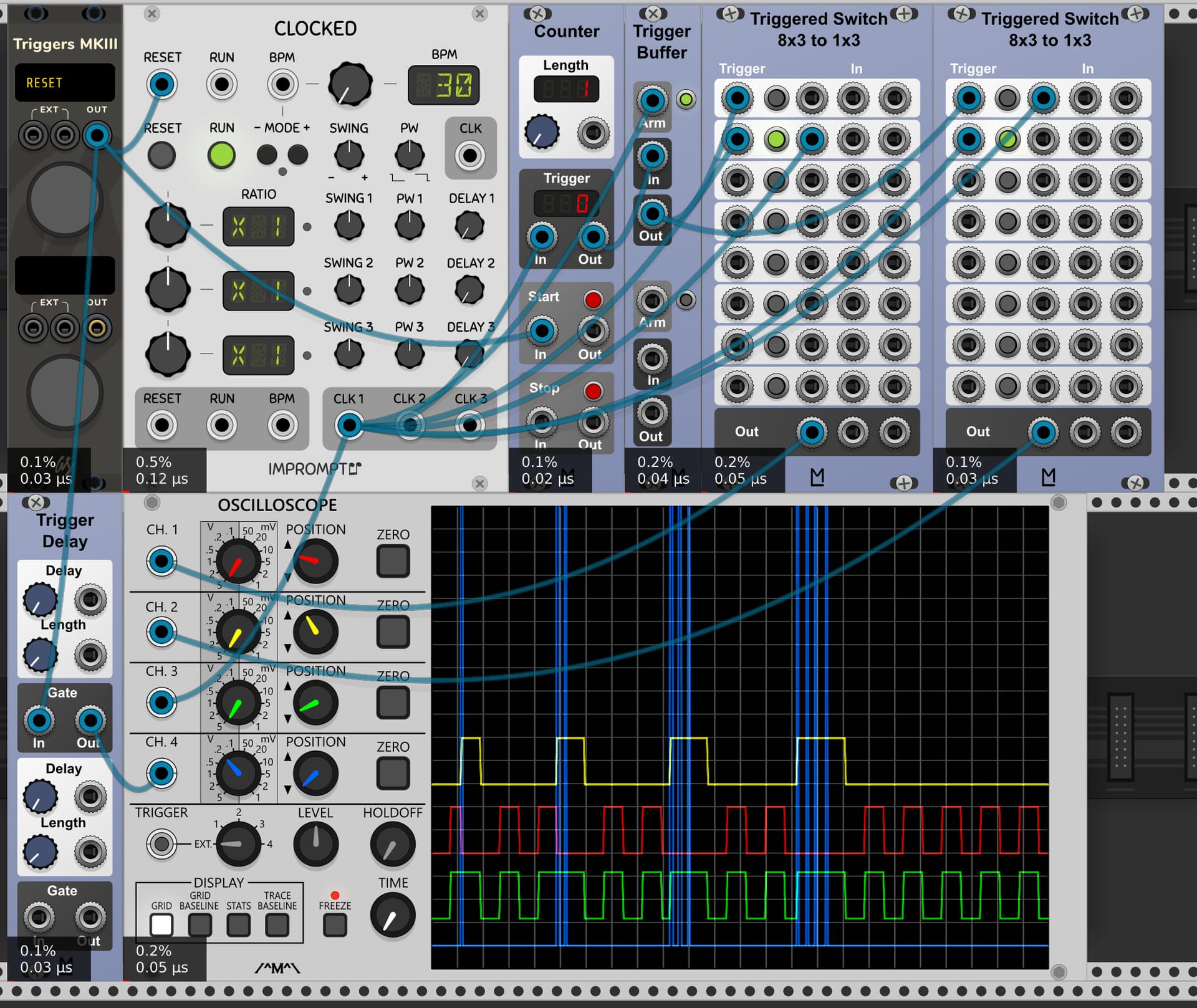
But it is easy to fix - Simply patch the HITS GATE output to HITS CV input, and set Hits CV amount to 100%. The HITS GATE goes high once the 2nd trigger is received, which bumps the number of hits up to match the pattern length. And the Reset properly turns the HITS GATE off and resets the HITS count back to length - 1. The other nice feature is the RESTS TRIG provides the output for my 2nd scenario - only the 1st trigger is passed, and all subsequent triggers are blocked.
This is a beautifully simple module to setup for my use case, and I never would have thought of it. But the module seems like overkill for such a seemingly simple task - both from a size standpoint, and from a feature standpoint.
I haven’t traced through to figure out how it works, but from the trace it looks like you solved it. The Trigger Buffer is the key module - I think I had seen it before thinking it might be useful, but never used it and of course forgot about it when I needed it.
It is a shame it doesn’t have a Reset input that disarms the module, without firing a trigger. Then it would exactly solve my 1st use case on its own. The 2nd use case could be solved with the addition of a logical XOR module.
I’ve developed an alternate patch using nothing but the Trigger Delay and some logic modules. Besides the obvious logic functionality, I use the logic modules to introduce sample delays so the logic doesn’t give false positives due to signal timing misalignment. It is a bit complex to setup, and uses 5 modules. But it is very compact, and no excess functionality in the modules.
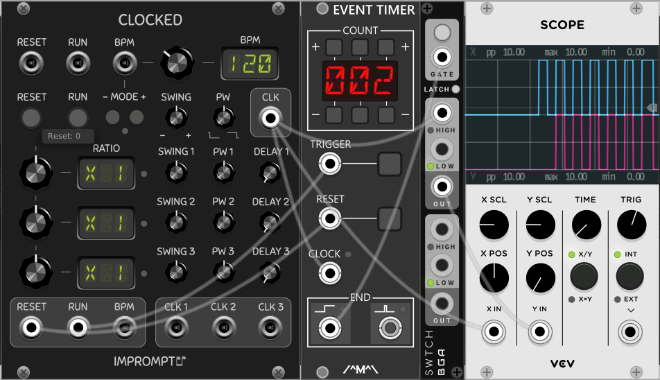
The output looks great on the Scope, but there is a timing issue - both channels get triggered on the first trigger. This can be visualized with the NYSTHI Mulivoltimetro set to min max mode. The X channel is supposed to skip the first trigger.
This can be fixed by introducing a 1 sample delay at your purple cable feeding into the Triggered Switch.
It does nicely solve both use cases, but now it takes 3 modules, and is just as wide as the Euclidean Sequencer solution (I don’t need gate output, just triggers).
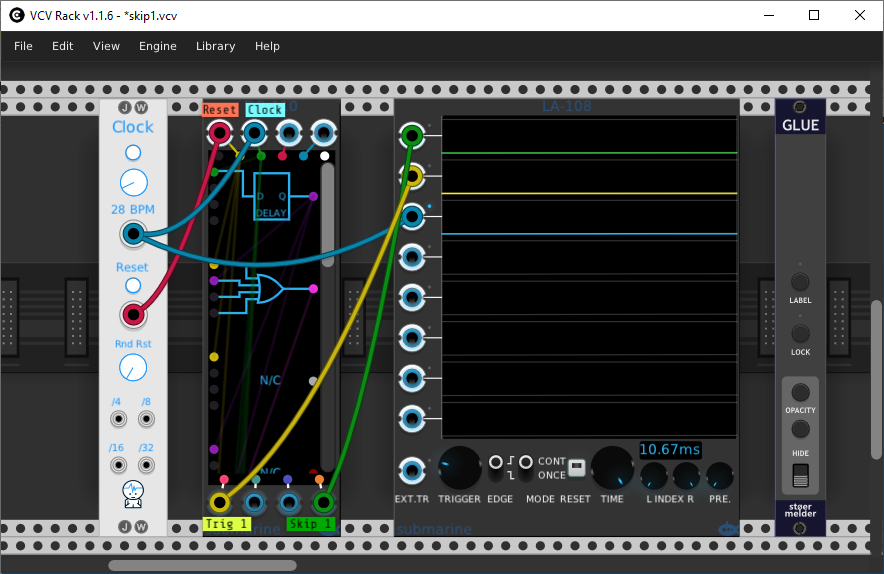
Well I finally figured out (sort of) the Submarine DO-110 (Digital Operators), and managed to get a good solution using that single module. That module had always been a complete mystery to me. I still have a question in the 2nd half of this post.
With the JW Clock, it automatically resets upon Run startup, and the Trig 1 output triggers only on the 1st clock pulse, and the Skip 1 triggers only on 2nd and subsequent pulses.
I can press the clock reset, and it does just that, Trig 1 fires on the first clock pulse after the reset, and Skip 1 fires on the 2nd and subsequent pulses.
So I guess I am happy with this, but I am still puzzled - I think there is a timing issue that I still don’t understand with the Digital Operators.
As I was experimenting trying to find a solution, I had some unused gates that I had defined but didn’t need. So I simply deleted them, leaving gaps at gates 3 and 4. Every thing works. But when I try to recreate the same logic without the gaps, it does not work - leading me to believe there is some timing issue, (or else a bug, or perhaps me totally misunderstanding something).
I was surprised I needed so many gates, and now I wonder if I understood the timing better, maybe I could get away with fewer gates.
So just how does timing work (down to the sample level) with this module?
Here is my logic that works:
Step  Gate       Input     Output

1     Delay      Clock     C

2     OR         Reset     O
                 C

3     NC

4     NC

5     SR-Latch   S=Reset   S
                 R=C
                 E=O

6     NOT        S         S'

7     D-Latch    D=S       D
                 E=Clock

8     D-Latch    D=S'      D'
                 E=Clock

9     AND        D         Trigger Once
                 Clock

10    AND        D'        Skip One
                 Clock
The gates operate from top to bottom. But you can’t internally connect a gate output to an earlier gate, so there are no race conditions and the results appear instantaneous to the rest of vcvrack. i.e. the entire logic of the device is calculated within 1 sample.
You shouldn’t have any need for the NC in slots 3 and 4. It’s possible that there’s a bug, but it seems unlikely given what I know about the implementation. It might be that you just misconnected things when you tried to rearrange it.
Nevertheless I’ll try to make time to try it out myself in case there is a bug there.
Yeah, that is what I thought must be going on. But I went over the compressed version multiple times, and couldn’t spot a logical difference. I even tapped into various intermediate gate outputs to try to figure out where things were going wrong. Everything was the same until I got to the D-Latch gates in the compressed version.
Unless you use a Delay gate of course, yes?! I wonder if that could be where a bug may lurk. Are there any limits to the number of delays for the same path?
No, there’s no limit to the number of delays for the same path.
And I stick by my statement. The delay always outputs the value of it’s input in the previous sample. So the logic that you craft in the device is calculated with a single sample. If your chain includes a delay, then your logic includes a single sample delay.
It took a long time, because it’s not easy to use my DO-xxx devices. Sorry.
I couldn’t find a problem. When I did it carefully, moving the devices and connections up the device to eliminate the N/C slots, I found that it still behaved exactly as it does in your original patch. So I don’t think there’s any bug there.
However, it’s hideous to use, so I intend to add extra information and options to the right click menu, so that you can select devices and connections using the menus, in addition to the dragging that you need to do now.
Thanks for taking the time to check it out. If you still happen to have the working version, could you post it, and I can try to figure out where I went wrong?
I agree the module is difficult to program. I think for me there were two main impediments. 1) It was difficult to get the big picture because so few gates were visible at one time - too much scrolling required. Not sure how you can address that. 2) Identifying pads with color did not work well for me - too many subtle variations to keep track of, and couldn’t associate the colors to any logical meaning. I don’t think a color blind person would have any success at all.
You might consider replacing the colors with alpha-numerics. For the top you could have A, B, C, D for the inputs, F for false, and T for true. For the Gate outputs you could simply use numbers - 1 for the 1st gate, 2 the 2nd, etc. I think I would find that much easier to grasp, double check “programming”, and document.
So stupid of me - My bugged version had level triggered D latched gates instead of edge triggered. And I had even identified where the bug was, and still couldn’t figure it out! I’m not familiar with all the gate varieties, and it didn’t stick with me that there were two types of D latches, with only the > symbol distinguishing them.
I should have posted my bugged version, and you probably would have spotted the error immediately.


 I’m not familiar with all the gate varieties, and it didn’t stick with me that there were two types of D latches, with only the > symbol distinguishing them.