@alfonso.santimone - I’ve a thread on some of the dev & some demos. I’ll respond over at Zoxnoxious analog synth VCV Rack demos to not hijack this thread
1 Like
I do not understand exactly what you mean. I’ll try to explain a bit the architecture of the product and maybe it makes it more clear for you.
This is a screenshot from a presentation I made where I show the architecture of the program. The presentation may not be very interesting for this topic but here’s the link if anyone interested on functional programming wants to watch it.
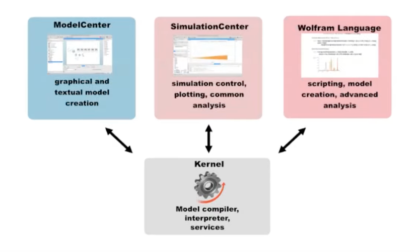
On the bottom you can see the “Kernel” which is a kind of language server. It includes the Modelica compiler and the routines to communicate with the clients shown on top.
Model Center is the program where you can create models graphically and textually. Those models are saved as Modelica models (textual format). The Modelica code stores all the information (equations, components, connections, graphics, simulation settings) what makes it a portable format that can be used in other Modelica tools.
Simulation Center is the program to control the simulations, plot results and perform common analysis.
Mathematica (Wolfram Language) can act as a scripting language for Modelica models. It allows you to create models from Wolfram Language equations, control simulations, perform more advanced analysis and retrieving equations, linearized models etc.
If users have Mathematica only, they can create SystemModeler models (Modelica) from equations. They can also perform simulations of this models and plot the results using the Wolfram Language. If they prefer to create models graphically, System Modeler (Model Center + Simulation Center) is the best option. Some users just need System Modeler and not Mathematica. At the end, a combination of both is what gives all flexibility.
When a user runs a simulation, we process the model and generate C++ code that is compiled and linked to our simulation engine. This results in an executable program that can be called by the clients (Simulation Center and Mathematica) to perform simulations.
1 Like
Very interesting, thanks for sharing this discussion with the rest of us, Andy and Leonardo!
2 Likes
We experience something similar. When processing a model, we perform a bunch of optimizations but we avoid the most complex ones because often times it does not worth the effort. To give you an example, on my current machine processing a mechanical model with around 1000 equations takes 12 seconds. Simulating the model takes 0.2 seconds. If we perform more aggressive optimization the compilation time will go above 12 seconds and the gain in simulation time would be minimal. In total, the spent time will be with normal optimization 12.2 seconds and with aggressive optimization most certainly more than 12.2 seconds.
Since System Modeler mainly a modeling tool it is often more important to our users being able of performing fast iterations to their models e.g. modifying the model and quickly see results. One thing we have not explored much is to do less optimzation to what we haven now, that way we could get results like 7 seconds to compile the model and 1 second to simulate (these numbers are made up).
You have a very nice representation of the circuit embedded in C++.
Your solver is more like a nodal (SPICE) solver then? or do you do symbolic processing to try to reduce the matrix size?
Thanks for the breakdown. I had a look at the generated code and it looks a bit slow is all, a bunch of if statements, and things split a lot between different functions. I’ll have a more in depth look over the trial period of the System Modeler. The graphical schematic editor looks gorgeous, and it’s great having such easy plotting, so being able to slot my own code generation somehow into this system would be really cool.
Thanks! I’ll abstract everything a little more to a factory method to create everything, and also support text file input, so hopefully I can use something like LTSpice to create the netlist, and add custom comments / spice directives for all the additional parts I need to help specify the solver parameters that way hopefully I can just use LTSpice directly to generate the input text to my solver / code generator.
Yes, my main code generation in current products is based on nodal analysis, but the matrix can be anything solved to the regular form A.x = z as a sparse symbolic matrix. I also have substitutions I perform on the entries for terms that can tend towards zero, so I can evaluate them with this apriori information to not pivot on something close to zero.
The matrix size doesn’t matter too much since it’s sparse. I currently solve the matrix using either Gaussian Elimination or LU decomp symbolically, and then the steps are optimised directly. I am able to manually set the order terms are solved to manipulate the location of non-linear terms, but I haven’t thus far spent too much time trying to do this automatically or reduce the matrix size before solving, but that is definitely an interesting idea, and something I’m sure Mathematica / System Solver can help with. I also solve multiple matricies, the regular Nodal “tick”, a special “warmup” version where call caps are set to zero, and DK / PDK versions which generate shearings and allow for pre-computation of the solutions, and interpolating multi-dimensional tables for “single step” direct solution, or a small number of steps for global iteration type solutions.
The other part that is important to me is pre-calculation of as many values as possible. I pull out there invarients to help the compiler as much as possible:
- randomisable component value constants (eg resistor / cap values)
- sample rate dependant constants / other values derived from constants (eg capacitor conductance based on the numerical integration used which is changes based on sample rate)
- parmeter “set” dependant constants (eg setting the filter cutoff, resonance etc)
- per sample constants
- inner solver loop constants
This might be a good point to tease a project I’ve been working on for the past year. First my background is in computational physics, but not at all in the electronic engineering area so this domain is totally new to me. My idea was to teach myself circuit simulation and build/breadboard hardware circuits as I go along. To do this I’ve been following Mortiz Klein’s excellent series which is brilliant for making things as simple as possible whilst still being actually usable and useful, and he does a great job of building intuition.
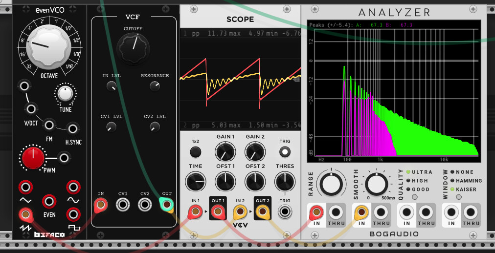
On the simulation side, I’ve been following @andy-cytomic’s ADC talk, mystran’s halite code and a few other resources. I started by implementing a symbolic MNA solver using sympy (in python) that autogenerates C++ code. I’ve managed to simulate the mixer (with diode clipping), envelope generator, and all VCF variants (starting from simple RC, though to the full diode ladder filter) with this approach. I’m really pleased with what I’ve managed so far and the diode filter actually sounds pretty nice to my ears. But it still has some pops and clicks in extreme use. I’ve been writing it all up as a series of blog posts comparing to the breadboarded circuits, which I will eventually make public. I’m now exploring state space methods to compare and contrast, and eventually hope to cover the full series of modules.
The aims are almost orthogonal to Andy’s though, in that this project will probably be:
- amateurish / entry-level / unsophisticated / high-ish CPU
- free / open source
- pedagogical
Once I’m happy enough with the quality of the code / blog, I’ll publish it and start a thread here. I’ll certainly have a few questions for the experts!

9 Likes
Great, work @hemmer! Thanks for letting us know what you’re up to. Computational physics sounds a lot more general than circuit simulation, but there will be plenty of overlap. I try to teach a bit as well (pedagogical), so hopefully that part isn’t too orthogonal.
The little pops and clicks are definitely a thing, that’s usually stuff not converging, and it’s generally non-trivial to come up with stuff that does converge quickly with a fixed number of iterations at a fixed and low sample rate. Most of the time a bunch of hand tuned hacks / tricks are needed to make everything behave nicely to minimise the crud like that. After so many years knowing where things are likely to go wrong I’m pretty much a professional digital crud finder, it doesn’t take me long to get a lot of different algorithms break! I’m pretty unkind on my own stuff to try and pick this up, but sometimes a little bit still slips through.
It’s good to see you’re using Julia. I really wanted to use it for my code generator, I was thinking of using Julia’s internal “macro / expression re-write tree code injection” type stuff to do some of the work, but then realised that I really needed to use with a Mathematica like n-ary tree structure for the expressions to make simplification / substitution easier, so just wrote it all in c++. I do like Julia though, and hope I can use it more in the future.
1 Like
I’ve watched and enjoyed lots of their videos as well. Watch out for his “diode ladder” filter, it’s not a diode ladder, it’s a Steiner-Parker partly differential Sallen Key filter. Diode ladder filters are the ones like in the TB-303 and EMS, which have a “rung” of capacitors hooked up between the a parallel series of diodes (or transistors).
For sure, I’ve found that ADC talk / papers very helpful! And in case it’s misinterpreted, the point on open source / free isn’t a dig, if I had invested 10+ years of R&D work to produce something of real commerical value, I’m certain I’d keep the source private too!
Basically solving ODEs/PDEs for fluid dynamics type of problems, so there is some common ground.
Yeah - so far I’ve only really used a vanilla Newton solve step, but it’d be good to see if e.g. damped methods work.
As for Julia, I’ve actually only really being playing around with the library GitHub - HSU-ANT/ACME.jl: ACME.jl - Analog Circuit Modeling and Emulation for Julia as I read the associated papers. My main implementation is still just in python → C++. Super neat and compact language though!
Sorry, you did clearly say you used Python. Python is a great language as well ![]()
@modlfo : do you have an idea of what are the best terms are to search for on the topic of manipulating a matrix to put all the non-linear elements in most efficient form to solve? I’d like to read some literature on the various methods, and knowing maths people there will be a lot of them, most likely invented a long time ago!
You’ve piqued my interest enough to chuck up a not-ready-for-public version of the blog (usual disclaimers). I am also interested in this topic and came up short. Basically I could “by hand” re-order the MNA matrix to have elements that change in the top left and fixed in the rest, and therefore only newton iterate the top left. This only works by hand for a very simple example of course:
For a more complex example I struggled to get anywhere:
I also asked on KVRAudio but didn’t get any bites (and that thread went off the rails…)
EDIT: I should add, in practice I don’t explicitly solve any Ax = b problems each iteration, I symbolically solve these at precomputation stage but the same logic applies.
1 Like
This looks great, thanks for sharing! Another key point to consider is that there is an additional partitioning for the top left corner, where you only need so solve a sub-set of the remaining voltages - those that are used to evaluate the non-linearities. The last voltages, which will appear in any linearly dependant only sub-parts of the circuit, can be evaluated once you have converged.
I also pre-compute all solutions symbolically. I see the trouble, but I’m not sure what can be done about it though. Can you please share the netlist of circuit you’re having trouble with so I can have a look as well?
(also I think the heading “Optimised Approach” is meant to be above the 2nd code snippet)
@hemmer how about construct your A matrix by ordering the x terms to include in it first entries all the voltages that the non-linearities require as inputs to evaluate, and all the voltages they output as well. That’s how I do it and it seems to work fine.
1 Like
Also, can we please use the correct terminology? This is a Steiner Parker filter, Mortiz Klein, as I said previously, has got this wrong:
Moritz Klein “diode ladder” filter
Here is an image of a Steiner Parker differential diode Sallen Key type filter:

This is a picture of a Diode Ladder filter:
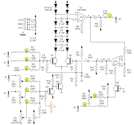
Please note the “rungs” of capacitors across the parallel lines of diodes / transistors.
Also the standard convergence check is not this:
converged = converged & (std::abs(v_1 - v_1_prev) < EPS);
But more like:
converged = converged & (std::abs(v_1 - v_1_prev) < std::abs(v_1)*relative_tolerance + absolute_tolerance);
where the relative and absolute tolerances depend upon the circuit a little.
1 Like
Completely - yes in practice I compute the subset of node voltages (basically output voltages, plus any needed for caps, NL pieces etc), if I understand your point.
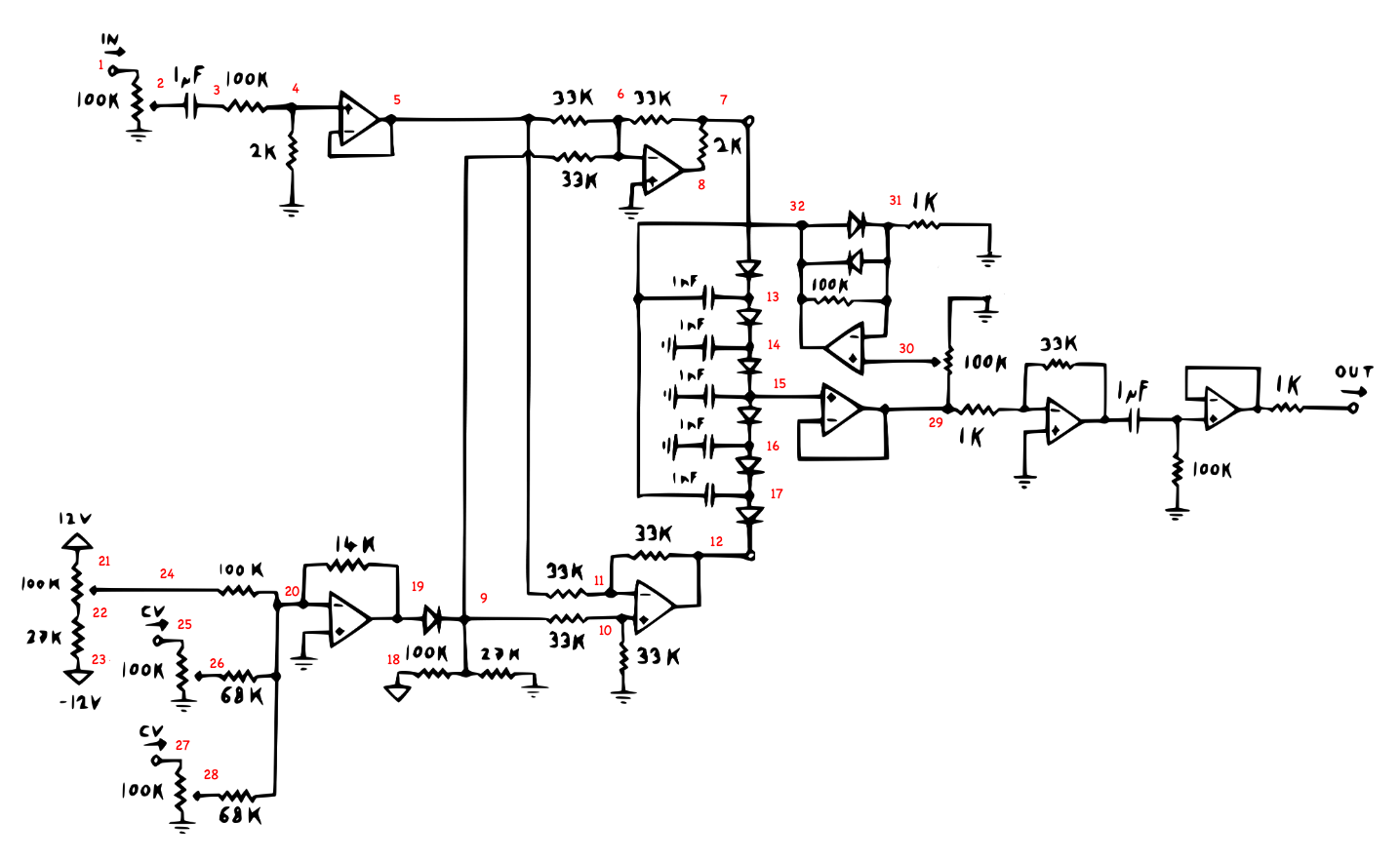
Netlist is here (gist:cc708518fb8307bcc68eba65184a854b · GitHub) all OpAmps ideal in this case, hopefully the format is vaguely interpretable (J is voltage probe / output). I mean it does “work” but I’m sure I’m doing more calculations than I need to because everything is inside the Newton loop, but the first half of the circuit is just getting levels, cv processing etc
That’s a nice idea, will try that! I suppose that’s similar to what I was trying in the “Re-arranging nonlinear elements” section of the linked notebook above, but there I was thinking about explictly decomposing submatrices (which fails because the other matrices aren’t necessarily invertable). It’s a while since I thought about this though, want to carefully revisit. In my solution, voltages (i.e. solutions) are never expressed in terms of other voltages (even though that is possible), is this the case for your solver (I see on slide 44 of ADC talk, v2 is given in terms of v3 for example)?
I mean I only became aware of this yesterday, I’ve not had a chance to update all my materials yet. I’ll add a note to the blog and cite you. I’m also deliberately following the notation / sections as named in Mortiz’s build docs, and don’t want to make things overly confusing. I can add quotes “diode ladder” ![]()
Good to know - do you have ballpark measures for these? Or just depends on your CPU budget etc.
balanced vs unbalanced ladder topology?
1 Like
Thanks! That’s perfect, and thanks for the diagram. Yes, the audio input and cv part can be replaced by two voltages sources:
v1 7 0 -vin + vcut
v2 12 0 -vin - vcut
The output part is also just a boost of x33, then a dc block, then buffer, so that can also be replaced just with vout = dcblock(33*v29), so then you’re only left with pretty much all non-linear elements anyway, but for the sake of this example I’ll keep all that so there is more circuit to test out these sorts of ideas and see how it goes.
By solving the MNA system with voltages in the first elements of the matrix will force voltages to be expressed in terms of previous voltages. I’ve found this sort of Nodally solved system best for stable convergence and computational efficiency. It is also possible to express things in a more “state space” form in terms of voltages over capacitors (or other memory elements). This can give better numerical performance, but I’ve found it not to be worth that small gain at the cost of faster convergence. You can also mix and match the two, some energy storage components that are not buffered from non-linear elements expressed nodally (as the difference between two voltages being solved for, which is nodal), and other ones being expressed as the voltage over the energy storage component being solved for, then the nodal voltages computed afterwards (which is what happens in state space methods).
Yes, you can set the rtol (relative tolerance) to zero and you get your previous method. If you check results in Spice there are usually three settings rtol for relative tolerance, and iatol / vatol a seperate voltage and current absolute tolerance amount, since currents and voltages have different magnitudes. Ideally using a power wave formulation would unit these sorts of tolerances, which is where WDF models come in.
Depending on the circuit I use around: rtol = 1e-4, vatol = 1e-7, I don’t normally bother solving for currents unless I’m debugging, and even then I don’t bother converging on them.
1 Like