Make sure there are no applications running that use the ASIO driver you’ve just set and press the “Start” button on the left.
If all goes well it should look something like this:
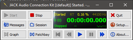
The yellow letters show the server status (it should say started). The green letters show the transport status, so don’t worry about the “stopped” there. I’ve not found a use for the transport here, but your mileage may vary.
Connecting the dots.
We’re going to use the JACK-Router ASIO driver in VCV. And that will work though the Audio-8 or Audio-16 VCV modules. These have 8 or 16 input and output ports respectively. And it would be cool if we could use all of them, but since the JACK-Router initially only has 4 in/out ports we shall have to remedy that.
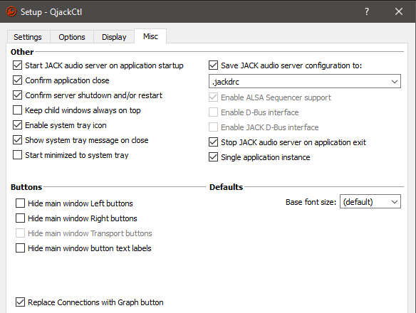
The files we have to change for that are located in the JACK installation directory under “Program Files”, so we need to start our text editor in administator mode (right-click → Run as administator):
Open “C:\Program Files\JACK2\jack-router\win64\JackRouter.ini” and change it to read like this:
[IO]
input=16
output=16
float-sample=1

[AUTO_CONNECT]
input=0
output=0
alias=1
Which, surprisingly, results in 16 input and output channels later on.
The float-sample setting is there for (in our case, hopefully non-existant) compatibility issues.
I’ve turned AUTO_CONNECT for the inputs and outputs off. If not, the default system input and output (mic and speakers) will always get connected to VCV Rack when it starts (which I don’t want. We’ll see later where that applies).
I’m not sure what the alias setting is for, so i left it alone 
Save the file, close the editor. There is an identical file in "C:\Program Files\JACK2\jack-router\win32" so i copied the modified one from the win64 directory to win32 to be safe.
I’m not totally sure if it’s necessary, but it doesn’t hurt to go to QjackCtl and press “Stop” and then “Start”.
And here we go. Run VCV. Plop in an Audio-16 module and set it as follows:
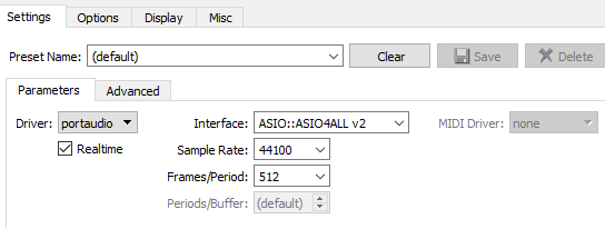
Driver: ASIO
Device: JackRouter (1-16 in, 1-16 out)
You should see the Rate and Blocksize at the values you set in QjackCtl setup and all ports light up green.
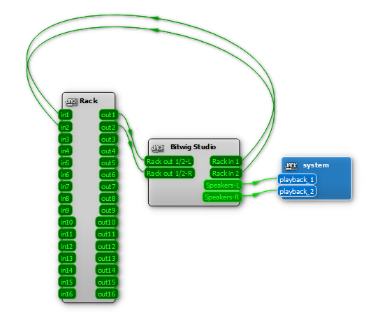
Now switch back to QjackCtl and press the Graph button. You should see something like this:
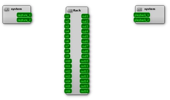
Remember that AUTO_CONNECT thing when we were editting that file? If we had left input and output on 1, capture 1 and 2 would be connected to the in1 and in2 of Rack and out1 and ou2 of Rack would be connected to playback 1 and 2.
If you just want to wing it in VCV, without Bitwig, you can still draw a connection from out1 and out2 of Rack to playback 1 and 2 to directly output sound, but for now leave it as is.
That “Rack” with the 16 ins and outs directly corresponds with the Audio-16 module. The Rack’s in1 to in16 in the graph in QjackCtl are the port under “From device” in the Audio-16, and the out1 to out16 are the ports under “To device”.

")
