Gates/Triggers
Gate to 1ms Trigger
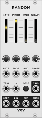
The RANDOM module works perfectly as a Gate to Trigger module. Simply make sure the PROB is at 100% and patch your gate to the TRIG input. A 1ms trigger will be output at the TRIG out.
Polyphonic Gate to 1 Sample Trigger
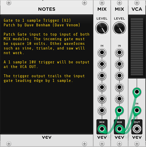
Generates a 10V trigger that is exactly 1 sample long upon the leading edge of an incoming 10V gate.
It is not stated in the NOTES documentation, but this construct fully supports polyphony.
EDIT - This is version 2 for this construct. It is simpler than the original
VCV Fundamental Gate to 1 Sample Trigger.vcvs (2.5 KB)
This patch takes advantage of the fact that each cable introduces a delay of exactly 1 sample. The incoming gate is patched to both MIX modules. The first MIX inverts the incoming signal and passes the result to the 2nd MIX. The 2nd MIX sums together the original gate with the inverted gate 1 sample delayed. The sum is passed to the VCA as both the CV and the input. The VCA prevents negative signals from passing through.
At rest both inputs at the 2nd MIX are 0V, so the output is 0V.
Upon initial receipt of a 10V input, the summing MIX receives the 10V input, while the negated signal remains 0V because it is delayed 1 sample, and the result is 10V.
One sample later, the negated input becomes -10V and the resulting sum is 0V.
When the input gate first returns to 0V, the delayed inverted input remains -10V, and the summing mix yields -10V. But the VCA blocks the negative voltage, so the output is 0V.
One sample later the inverted value returns to 0V, and we are back at rest.
Gate to 33 Sample Trigger
EDIT - This is version 2 for this construct. It is simpler than the original
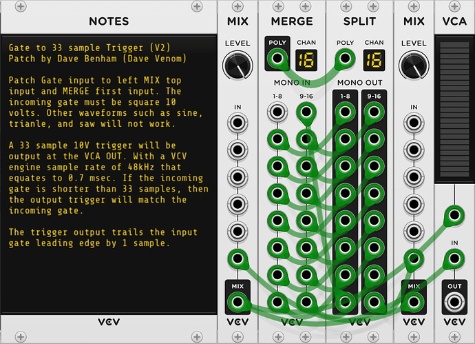
This is basically the same as the 1 Sample Trigger, except it uses recursive patching of MERGE and SPLIT to extend the delay to 33 samples. At an engine rate of 48kHz, that equates to 0.7 ms
VCV Fundamental Gate to 33 Sample Trigger.vcvs (6.6 KB)
Gate / Trigger Generator
Generates a precisely timed gate or trigger upon the leading edge of an incoming gate or trigger.
VCV Fundamental Gate - Trigger Generator.vcvs (6.2 KB)
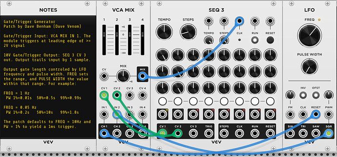
I’m really happy with the simplicity and elegance of this patch. The SEQ 3 uses only 2 steps. The first step represents the idle state, waiting for a trigger. The second step is the active output of the resultant gate or trigger.
Two triggers are needed for each gate output - the user patched input gate, and the end of gate trigger from the LFO. The VCA MIX VCAs are used as switches to control which triggers are allowed through, and the MIX output is sent to clock the SEQ 3. The SEQ 3 CV 1 is high and enables the input trigger only during the step 1 idle phase. The CV 2 is high and enables the end of gate trigger only during the step 2 output phase.
The patch relies on the fact that the SEQ 3 step transition is instantaneous. So when the end of gate trigger transitions from step 2 to step 1, the SEQ 3 will not be re-triggered if the input gate is still high. A subsequent gate/trigger cannot be generated until we return to step 1 AND the input gate must return to low so that a new leading edge high trigger can be recognized.
The length of the output gate is controlled by the LFO frequency and Pulse Width. The LFO is set to unipolar 0-10V mode, and inverted, so that a cycle starts low, and when it goes high it represents the end of gate trigger. The LFO is reset upon receipt of the triggering input gate, so step 2 always starts with the beginning of an LFO cycle.


