VCV Fundamental Constructs

Definitely a Bernouli Gate can be constructed. I still need to wrap my head around the different modes before I attempt to build one. If one construct that supports all modes becomes too large, then it might be split into different constructs, one per mode.

A companion topic for comments and or curated examples would be cool. But I think the table of contents at the top will allow this topic to remain functional even if it gets “littered” with lots of comments etc.

I nearly had it working, but the timing seemed way off and the A-Output was doing strange things. The 1>4 Switch has a fade-in and fade-out of about 2.4ms which could be very problematic for accurate switching.

I agree to open a discussion thread parallel to this topic. Maybe a mod would be so nice to move our postings to that thread. @DaveVenom would you please start that discussion thread?

Gates/Triggers

Gate to 1ms Trigger

The RANDOM module works perfectly as a Gate to Trigger module. Simply make sure the PROB is at 100% and patch your gate to the TRIG input. A 1ms trigger will be output at the TRIG out.

Polyphonic Gate to 1 Sample Trigger

Generates a 10V trigger that is exactly 1 sample long upon the leading edge of an incoming 10V gate.

It is not stated in the NOTES documentation, but this construct fully supports polyphony.

EDIT - This is version 2 for this construct. It is simpler than the original

VCV Fundamental Gate to 1 Sample Trigger.vcvs (2.5 KB)

This patch takes advantage of the fact that each cable introduces a delay of exactly 1 sample. The incoming gate is patched to both MIX modules. The first MIX inverts the incoming signal and passes the result to the 2nd MIX. The 2nd MIX sums together the original gate with the inverted gate 1 sample delayed. The sum is passed to the VCA as both the CV and the input. The VCA prevents negative signals from passing through.

At rest both inputs at the 2nd MIX are 0V, so the output is 0V.

Upon initial receipt of a 10V input, the summing MIX receives the 10V input, while the negated signal remains 0V because it is delayed 1 sample, and the result is 10V.

One sample later, the negated input becomes -10V and the resulting sum is 0V.

When the input gate first returns to 0V, the delayed inverted input remains -10V, and the summing mix yields -10V. But the VCA blocks the negative voltage, so the output is 0V.

One sample later the inverted value returns to 0V, and we are back at rest.

Gate to 33 Sample Trigger

EDIT - This is version 2 for this construct. It is simpler than the original

This is basically the same as the 1 Sample Trigger, except it uses recursive patching of MERGE and SPLIT to extend the delay to 33 samples. At an engine rate of 48kHz, that equates to 0.7 ms

VCV Fundamental Gate to 33 Sample Trigger.vcvs (6.6 KB)

Gate / Trigger Generator

Generates a precisely timed gate or trigger upon the leading edge of an incoming gate or trigger.

VCV Fundamental Gate - Trigger Generator.vcvs (6.2 KB)

I’m really happy with the simplicity and elegance of this patch. The SEQ 3 uses only 2 steps. The first step represents the idle state, waiting for a trigger. The second step is the active output of the resultant gate or trigger.

Two triggers are needed for each gate output - the user patched input gate, and the end of gate trigger from the LFO. The VCA MIX VCAs are used as switches to control which triggers are allowed through, and the MIX output is sent to clock the SEQ 3. The SEQ 3 CV 1 is high and enables the input trigger only during the step 1 idle phase. The CV 2 is high and enables the end of gate trigger only during the step 2 output phase.

The patch relies on the fact that the SEQ 3 step transition is instantaneous. So when the end of gate trigger transitions from step 2 to step 1, the SEQ 3 will not be re-triggered if the input gate is still high. A subsequent gate/trigger cannot be generated until we return to step 1 AND the input gate must return to low so that a new leading edge high trigger can be recognized.

The length of the output gate is controlled by the LFO frequency and Pulse Width. The LFO is set to unipolar 0-10V mode, and inverted, so that a cycle starts low, and when it goes high it represents the end of gate trigger. The LFO is reset upon receipt of the triggering input gate, so step 2 always starts with the beginning of an LFO cycle.

3 Likes

Yes - there are a number of constructs where I would like to use the 1>4 and/or 4>1 switches, but the cross fade feature is problematic. I’m sure the fade is to prevent pops when switching audio signals, but it sure would be nice if the switches had a context menu option to disable the fade feature for CV.

So instead of the switches, I typically use either VCA MIX or SEQ 3, depending on what I am trying to accomplish. Both of those can do instantaneous switching. But they sure do take a lot of space :frowning:

I’ve got some Bernoulli Gate constructs to post.

The more I think about it, the more I am convinced that keeping everything in one topic is better. It is much easier to comment or discuss about a particular post by simply replying or quoting from within the same topic. That is not so easy from a different topic. The table of contents will still allow people to find the relevant constructs quickly. The comments/discussions will end up being a bit helter skelter, but that is no different than if they were in a different topic.

1 Like

I made a Bernoulli gate and a Turing machine analog but I haven’t made the transition to V2 yet:

1 Like

Random Events / CV

I hope to add some descriptions of how these constructs work at a later date.

Simple Bernoulli Gate

Randomly send gates or triggers to one of two channels.

The probability setting always specifies the percent chance of selecting channel 2

EDIT - New version V2 uses OCT to round instead of QNT

VCV Fundamental Simple Bernoulli Gate.vcvs (12.6 KB)
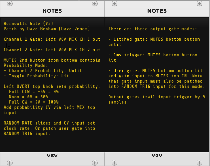
Bernoulli Gate

Randomly send gates or triggers to one of two channels.

The probability setting can either specify the percent chance of selecting channel 2, or percent chance of toggling between channels 1 and 2.

EDIT - New version V2 uses OCT to round instead of QNT

VCV Fundamental Bernoulli Gate.vcvs (20.8 KB)

Bernoulli Toggled Flow / Gate

The construct become very simple if all we need is the toggle mode. The RANDOM probability feature makes construction almost trivial.

And we pretty much get for free an entirely new feature - Two switched channels controlled by the gates that control flow of signals through A or B.

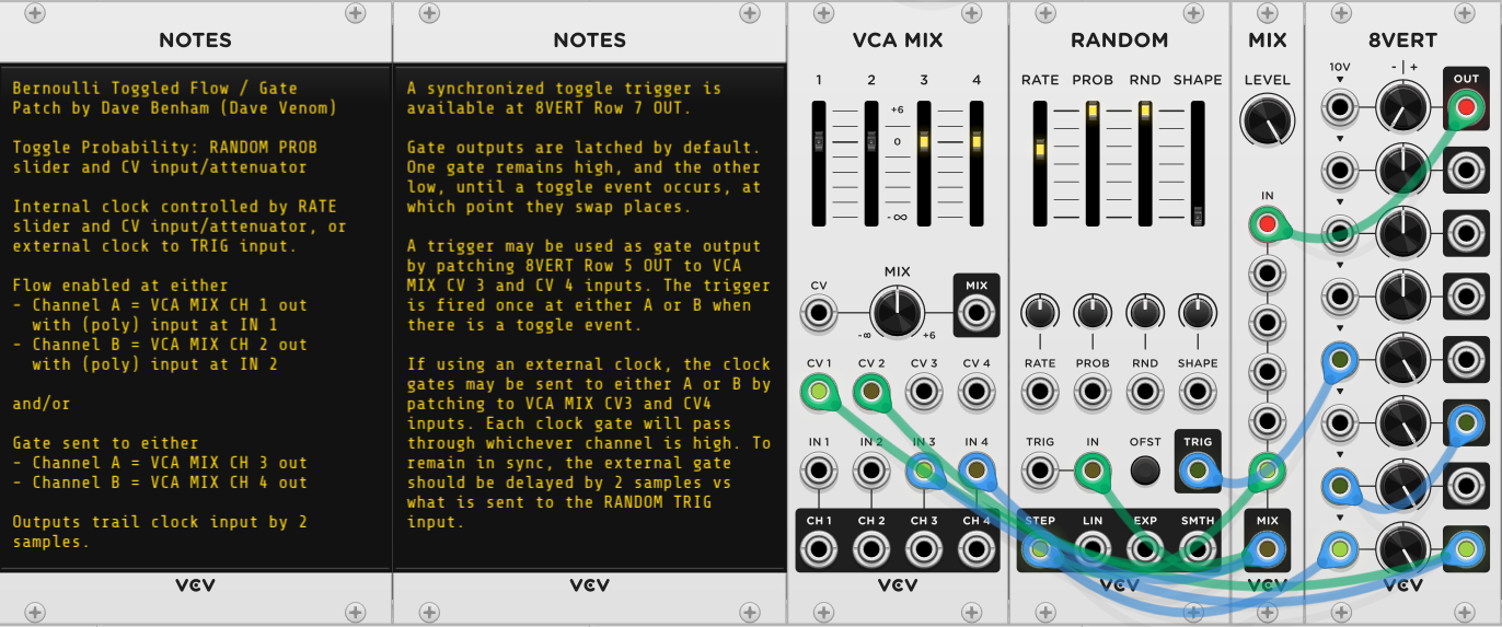
VCV Fundamental Bernoulli Toggled Flow - Gate.vcvs (6.5 KB)
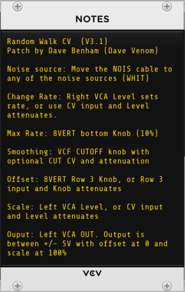
Random Walk CV

My attempt to provide a random walk similar to (but definitely different than) the Bogaudio WALK module. The VCV RANDOM module can also do a form of random walk, but this construct supports more localized variability within the context of a slowly changing average.

EDIT - This version 3.1 uses the same concepts as before, but the implementation has been largely redesigned to make it significantly smaller and use less CPU. Version 3.1 fixed a bug in V3 where an 8VERT knob was accidently nudged off its intended -10V setting

VCV Fundamental Random Walk CV V3.vcvs (19.4 KB)

Here is a somewhat cryptic explanation of how the random walk works:

Base Output - VCA MIX

  • Sums two inputs
    • Current value + random delta derived from noise: VCA CV is 100% (10V) only if magnitude <=5, else 0%
    • Current value - random delta derived from noise: VCA is 100% only if the first magnitude >5, else 0%
  • This arrangement always guarantees output within +/- 5V

The Random delta is derived from

  • Noise - running average of 6 consecutive samples. Passed through series of 6 Mutes, with each one going to a MIX set to average the inputs.
  • Times 8VERT attenuation for max rate of change (defaults to 10%)
  • Times VCA attenuation for final rate of change

To determine if the (Current value + next delta) magnitude is >5, use a modified combination of full rectifier + comparator:

  • Split signal in two
    • multiply 1st by 0.1 and use as CV for 1st VCA in a VCA MIX, with 10V input
    • multiply 2nd by -0.1 and use as CV for 2nd VCA in a VCA MIX, with 10V input
  • The VCA MIX output yields the rectified value (absolute magnitude) divided by 10 (value between 0 and 1)
  • Pass through OCT to round to two possible values
    • 0 (original value within +/- 5V range)
    • 1 (value outside of +/- 5V range)
  • Multiply OCT result by 10 to get controlling CV for the - delta signal
  • Negate the prior result (NOT gate) to get the controlling CV for the + delta signal

Correct sample delays need to be carefully inserted to make sure all signals arrive at the Base output VCAs at the same time. I use mostly MUTES to insert sample delays.

Final output

  • The Base Output is sent through low pass VCF for smoothing
  • Then offset added
  • Then final attenuation via VCA yields final output
4 Likes

Cool patch - I had some fun playing with it. But I’m not sure I see any Bernoulli gates. You only have one gate channel per random choice. Bernoulli gates could replace some modules in your patch, but I don’t see how any construct in your patch replicates the functionality of a Bernoulli gate.

I think each trio of Random/Unity/Random in your patch can be replaced by a single V2 RANDOM module - it gives you control over the probability that an incoming trigger will select a new random value.

I just took a look, the relevant bit is in the top center right but isn’t labeled. The cymbal and snare sound are controlled by an 8vert that sets the percentage chance of either of them being triggered.

Yep, I see it now - thanks. The notes in the patch were a bit misleading.

Math - Constant values, Scale values, and Multiply two inputs

Constant Big Integer CV

Easily generate a precise integral constant voltage with a range of +/- 1,000,000

VCV Fundamental Constant Big Integer CV.vcvs (4.9 KB)

7 x Constant CV +/- 100 or Scale 10

  • Generate up to 7 constant CV values with a range of +/- 100

or

  • Multiply input (polyphony supported) by up to 7 different scale factors with range of +/- 10

This is especially convenient for Constant CV as the knob percent number equals the output voltage.

VCV Fundamental 7 x Constant CV 100 - Scale 10.vcvs (2.9 KB)

7 x Constant CV +/- 1000 or Scale 100

  • Generate up to 7 constant CV values with a range of +/- 1000

or

  • Multiply input (polyphony supported) by up to 7 different scale factors with range of +/- 100

This is especially convenient for Scaling input CV as the knob percent number equals the scale factor.

VCV Fundamental 7 x Constant CV 1000 - Scale 100.vcvs (4.1 KB)

Polyphonic Scale +/- 10

Scale any input (polyphony supported) by a constant factor ranging from -10 to 10, with option to add offset CV input before scaling. This is a simple and compact construct.

VCV Fundamental Polyphonic Scale 10.vcvs (2.4 KB)

Polyphonic Scale +/- 100

Scale any input (polyphony supported) by a constant factor ranging from -100 to 100, with option to add offset CV input before scaling. This is nearly twice the size as the Scale 10, and the large scale factors are rarely needed, but it is very convenient to use because the knob percent number reads directly as the scale factor (100% = 100 x input)

VCV Fundamental Polyphonic Scale 100.vcvs (3.7 KB)

Multiply A x B

Multiply A (clipped at +/- 20V) times B (unconstrained)

VCV Fundamental Multiply.vcvs (14.1 KB)

1 Like

For the noobs here, what’s a Bernoulli Gate?

Randomly send gates or triggers to one of two channels.

Math - Comparators

All of these constructs compare incoming voltage against either constant CV, or else against another voltage source, and output either high (10V) or low (0V) depending on the relationship between the two.

One possible use for these is to convert analog signals into binary values (0 = False, 10 = True) so that logical operations (NOT, AND, OR) can be performed elsewhere (logic constructs still to come).

All the comparators use the same basic technique. A MIX sums together A + inverse B + 5 V. If A is >= B, then the result will be >= 5V. If A < B the result will be < 5V. That result is then used as CV for a VCA to attenuate a 1V input. The result will be >= 0.5 only if A >= B. That then passes through OCT to round the value to either 1 if A>=B, or 0 if A<B. Finally the result is amplified by a factor of 10 by VCA MIX to get the final output of 0V or 10V.

Many of my constructs elsewhere in this topic rely on some variation of this technique.

Comparator

Outputs 10V if A >= B. B can be constant CV, or another input signal.

VCV Fundamental Comparator 16.vcvs (16.8 KB)

Polyphonic Comparator

Outputs 10V if A >= B, with support for polyphonic inputs for both A and B.

VCV Fundamental Polyphonic Comparator.vcvs (12.3 KB)

Comparator x 16

16 Comparators that output 10V if A >= B. There are 16 inputs for A, and B is either a universal constant CV, or a monophonic input that is replicated for each of the comparators.

Window Comparator

Four outputs available that compare A against B, with a Window range to test if A equals B. Both B and the Window can be constant CV, or an input signal.

  • 10V if A >= B
  • 10V if A<B
  • 10V if A=B within a Window tolerance (|A-B| <= Window)
  • 10V if A <> B within a Window tolerance (|A-B| > Window)

VCV Fundamental Window Comparator.vcvs (15.9 KB)

Polyphonic Window Comparator

A polyphonic version of the Window Comparator. Both A and B are polyphonic inputs. The Window is either universal constant CV, or else a monophonic input that is replicated for each of the comparators.

The output is polyphonic.

VCV Fundamental Polyphonic Window Comparator.vcvs (29.8 KB)

Schmitt Trigger Comparator

A comparator with memory and two thresholds that is resistant to noise on the inputs. See the documentation in the Notes for a full description.

VCV Fundamental Schmitt Trigger.vcvs (11.9 KB)

4 Likes

MATH - Min / Max

Send two inputs in, and one output has the maximum voltage at that instant, and the other output the minimum.

A comparator creates two binary signals, one is 10V if A>=B, and the other is 10V if A<B. Then four VCAs are used as switches with the results of the comparison as the CV. The switches direct the signals to the correct outputs. Each input is sent to both outputs, but the VCAs only allow the correct values through.

Min / Max

Support for monophonic inputs A and B

VCV Fundamental Min Max.vcvs (12.5 KB)

Polyphonic Min / Max

A polyphonic version of the above.

VCV Fundamental Polyphonic Min Max.vcvs (23.3 KB)

3 Likes

LOGIC

All of the following logic constructs assume all inputs are binary with a voltage value of 0V (False) or 10V (True). If you have unconstrained analog inputs, you can use any of the Comparator constructs to convert them to binary before feeding them into a logic gate.

All of the logic constructs support polyphony. If all inputs are polyphonic, then the outputs will be polyphonic as well.

Most of the constructs include their own copy of an 8VERT to supply constant CV. But that can become wasteful if there are many logic gates in your patch. Feel free to patch in the needed constant CV from elsewhere and remove the redundant 8VERTs if you can.

Polyphonic NOT Gate

VCV Fundamental Polyphonic NOT Gate.vcvs (2.0 KB)

Polyphonic Simple OR Gate

It is “common knowledge” that a mixer can be used as a simple OR gate. However, the outputs are not restricted to 0V or 10V. This construct is included for completeness.

VCV Fundamental Polyphonic Simple OR Gate.vcvs (873 Bytes)

Polyphonic OR Gate

This slightly more complex version of an OR gate forces the output to be 0V or 10V.

VCV Fundamental Polyphonic OR Gate.vcvs (2.6 KB)

Polyphonic Simple NOR Gate

Like most of the logic constructs, the negated version simply appends NOT logic to the base construct. The simple NOR may have false outputs that are < 0V.

VCV Fundamental Polyphonic Simple NOR Gate.vcvs (2.0 KB)

Polyphonic NOR Gate

Again, a bit more sophisticated version to force outputs to be 0V or 10V.

VCV Fundamental Polyphonic NOR Gate.vcvs (2.9 KB)

Polyphonic AND Gate

Another “common knowledge” construct that is included for completeness.

VCV Fundamental Polyphonic AND Gate.vcvs (876 Bytes)

Polyphonic NAND Gate

VCV Fundamental Polyphonic NAND Gate.vcvs (2.7 KB)

Polyphonic XOR Gate

An XOR gate can be created by combining OR AND NAND

VCV Fundamental Polyphonic XOR Gate.vcvs (4.6 KB)

Polyphonic XNOR Gate

XNOR can be created by combining NOR OR AND

VCV Fundamental Polyphonic XNOR Gate.vcvs (4.8 KB)

Trivial Logic Demo

The following patch demonstrates each of the logic gates. There are two versions of the demo.

  • The version at the top includes the 8VERT for each logic gate.
  • The version at the bottom shows how it might look if the gates share a common 8VERT.

For each version, the top two MUTES buttons represent the A and B inputs, with lit representing FALSE, and unlit TRUE. The ML Voltmeter next to each gate shows the current value for A and B at the top, as well as the resultant output at the bottom.

VCV Fundamental Logic.vcv (5.7 KB)

4 Likes

Clock Modulators / Frequency Dividers

Chainable 3 Stage Flip Flop - Resets ON

A SEQ 3 module with the correct settings works perfectly as a Flip Flop. And they can be chained by sending the Reset and Clock output triggers from one into the input of the next. This version sets all gates ON upon reset.

Note that each chained SEQ 3 flip flop runs one sample behind its parent unless you patch appropriate sample delays to the parent gate outputs.

VCV Fundamental Chainable 3 Stage Flip Flop - Resets ON.vcvs (3.8 KB)

Chainable 3 Stage Flip Flop - Resets OFF

This is identical to the previous construct, except all gates are set to OFF upon reset.

VCV Fundamental Chainable 3 Stage Flip Flop - Resets OFF.vcvs (3.8 KB)

Binary Frequency Divider 1-512

This construct chains 3 SEQ 3 flip flops together, but also adds carefully constructed sample delays to ensure that all gate outputs are in sync with each other. It provides power of two divisions from 1 to 512.

VCV Fundamental Binary Frequency Divider 1 - 512.vcvs (21.8 KB)

Clock Divider - Integers 1 - 8

This uses SEQ 3 modules and sample delays to provide integral clock divisions from 1 - 8.

VCV Fundamental Clock Divider Ints 1-8.vcvs (24.2 KB)

Clock Divider - Integers 1 - 16

4->1 Switches are added to extend the concept to integers beyond 8.

VCV Fundamental Clock Divider Ints 1-16.vcvs (47.8 KB)

Clock Divider - Any N

This patch is inspired by an idea/patch from Loops. It provides a reliable way to set a clock divisor of any value by simply entering a formula for a knob parameter: 2.0001 / N, where N is the desired divisor.

VCV Fundamental Clock Divider Any N.vcvs (10.3 KB)

I simplified Loops’ original idea by using a single SEQ 3 to take the place of a RANDOM and SEQ 3 pair.

The SEQ 3 uses 2 stages:

  • Stage 1 - Waiting for the Nth clock input
  • Stage 2 - Waiting for the triggering Nth clock input to go low

The RANDOM trigger has two clock inputs, each enabled/disabled by a VCA

  • The clock input which is only active during SEQ 3 stage 1
  • The end of stage 2 trigger which is only active during SEQ 3 stage 2

The SEQ 3 clock receives two inputs, also controlled by VCAs

  • The RANDOM STEP output, only active during stage 1
  • The negated clock input, only active during stage 2

The sum of the current RANDOM output + the delta passes through another VCA that is only active during stage 1.

The RANDOM starts out with an output of 0V. Each successive clock trigger adds the delta (2.0001/N), until a value >=2V is reached, which triggers the SEQ 3 to go to the second stage.

As long as the triggering clock remains high, the negated signal is low, so the 2nd stage remains active. Once the clock goes low, the negated signal goes high, which triggers the SEQ 3 to return to stage 1. It also triggers the RANDOM, but the 3rd VCA is off, so the IN receives 0V and the RANDOM is reset back to 0V - ready to start a new cycle.

I avoided the need of an 8VERT by using the various outputs available from the SEQ 3.

The stage gates provide the signals that control the VCAs.

The CV1 step 1 sets the delta (the divisor)

Both steps for CV2 are permanently set to -10V, which is needed to negate the incoming clock.

CV3 is permanently set to 10V at stage 2 to be used for the gate output. I could have used the 2nd stage gate as the gate output. But I opted to use CV3 to keep user patch points separate from the construct patch cables.

The SEQ 3 also conveniently provides the trigger for stage 2 as well.

Clock Multiplier 1-16

It wasn’t long ago I thought there would be no practical way to create a clock multiplier. But then I realized the RANDOM STEP output already has the ability to subdivide any given time unit by integral values from 1 to 16 via the SHAPE. All that is needed is a comparator that can detect each time the output voltage jumps to the next step (could be a positive or negative jump)

An inverted MIX module with a -10V constant CV plus the STEP output feeds the RANDOM input, so it toggles between 0V and 10V. The minimum step size (at 16 steps) is 0.625V. Multiply that value by 4 and you have more than enough to trigger another RANDOM, which also outputs a clean 1ms 10V trigger of it’s own.

To detect each jump, I use a MIX to sum the current STEP output with the inverted value of the previous sample that has been delayed 1 sample. I do the same with the inverted current value and the original previous sample. One of those sums will be positive going from 0 to 10, and the other when going down from 10 to 0. Both are used as CV for a VCA, with 10V input. Only the positive jump will register. The VCA MIX multiples by 4, which is enough to trigger the 2nd RANDOM.

Note that the clock divider may stall if the incoming clock rate changes too quickly. If that happens, simply momentarily disconnect the blue cable from the RANDOM STEP output to the MIX input.

One important thing that I did not discuss in the documentation - You can opt to randomly drop beats by setting the PROB slider below 100% on the right RANDOM module. This works really well with percussive voices to introduce life to the rhythm.

VCV Fundamental Clock Multiplier 1-16.vcvs (8.5 KB)

3 Likes

Wave Manipulation

Polyphonic Rectifier

A VCA functions as a half wave rectifier if you feed the signal into the CV input and 10V constant CV into the input. That will block the negative signal, leaving just the positive signal.

Invert the signal before rectifying, and you have the inverted negative signal. Invert again and you have the original negative signal.

A mixer can sum together the positive signal and the inverted negative signal to get full rectification.

It is quite simple with additional inverters to get all possible outputs. The only trick is to make sure each signal path goes through the same number of patch cables so they all stay in sync.

The Version 2 VCV VCA has great support for polyphony, and there is no need to replicate the constant 10V to multiple channels when rectifying a polyphonic signal.

VCV Fundamental Polyphonic Rectifier.vcvs (5.6 KB)

Amplitude Modulation

If your modulator is already unipolar, then all you need is a VCA. This construct includes convenient offset capability so it can work with bipolar modulators.

VCV Fundamental Amplitude Modulation.vcvs (3.3 KB)

Polyphonic Amplitude Modulation

This version simply adds a MERGE so the offset can be replicated to mix in with the polyphonic modulator.

If either the carrier or modulator is monophonic, then it need not be replicated - the VCA will automatically replicate the signal to match the channel count of the other. But if both inputs are polyphonic, then they should have the same number of channels.

Note that the cable that feeds the MERGE module must be replicated to match the number of channels in the modulator. For example, if the Modulator has three channels, then the MERGE should have the first three inputs fed by the top 8VERT OUT.

VCV Fundamental Polyphonic Amplitude Modulation.vcvs (4.0 KB)

Ring Modulation

Ring modulation requires multiplication of negative values. But the VCA CV input blocks negative values. So the carrier wave must be rectified with the positive signal going to one VCA, and the negative signal inverted before feeding into the 2nd VCA. The negative result must than be inverted again and then summed with the positive result. Management of sample delays is critical to make sure the summed signals align properly.

VCV Fundamental Ring Modulation.vcvs (5.4 KB)

Polyphonic Ring Modulation

Just need to swap in four VCA modules to replace the VCA MIX to get flexible polyphonic support.

As with the polyphonic amplitude modulation, if either the carrier or modulator is monophonic, then it need not be replicated - the VCAs will automatically replicate the signal to match the channel count of the other. But if both inputs are polyphonic, then they should have the same number of channels.

VCV Fundamental Polyphonic Ring Modulation.vcvs (6.5 KB)

Hybrid Amplitude / Ring Modulation

This combines features of the amplitude modulation and ring modulation.

If the modulator is bipolar, then offset by 5V and you have amplitude modulation. Use 0V offset to get ring modulation. Values in between give hybrid results. I don’t know what to call it if you use negative offset.

Polyphonic Hybrid Amplitude / Ring Modulation

A polyphonic version of the above.

As with the amplitude modulation, the MERGE module must have the cable feeding it replicated to match the number of channels in the modulator.

VCV Fundamental Polyphonic Hybrid AM - RM.vcvs (8.8 KB)

3 Likes

Timing

Simple CV Fade In/Out

This is simply an ADSR with a latching button to establish a long term gate to turn the CV on or off (with optional gate input), and a VCA to provide exponential response for more option on the shape of the fade in and out.

This is very effective and simple to build, but the ADSR attack and release timings are very inaccurate (but consistent)

VCV Fundamental Simple CV Fade In-Out.vcvs (5.9 KB)

Precise CV Fade In/Out

This uses a completely different design to achieve precise timing of the fade in and out times.

The SEQ 3 is used to keep track of what stage we are in, and establishes controlling voltages and gates for the different stages. The fade in/out shape and length are established by an LFO that gets reset at the beginning of each fade stage, so the shape and timings are consistent. The LFO signal also determines when the fade stage ends - it is scaled so that when the peak is reached, it is just enough to trigger the next SEQ 3 stage. VCAs are used as switches to control the flow of various voltages so they go to the correct destination depending on the stage.

VCV Fundamental Precise CV Fade In - Out.vcvs (12.5 KB)

Countdown Timer

This construct requires two different modules to serve as memory. The SEQ 3 keeps track of what stage the countdown is in (Waiting to start, Counting Down, or Countdown Complete), as well as establish controlling voltages and gates. A RANDOM is used to keep track of how many counts are left. At the input, each 0.0001 volt represents one count. That value is scaled up to 1V per count, and then Reset stores the initial count in the RANDOM. Upon countdown start, each clock tick stores the current value minus 1V. The countdown is complete once 0V is reached.

VCV Fundamental Countdown Timer.vcvs (17.2 KB)

Visual Countdown Timer

Same as above, but additional modules are used to compute the digits of the various powers of ten in the count number across polyphonic channels so they can be graphically displayed by a VCA. This can be handy as a performance aid to keep track of how much time is left.

VCV Fundamental Visual Countdown Timer.vcvs (25.5 KB)

Compact Countdown Timer

After building the Clock Divider Any N, I realized I could build a much smaller countdown timer as long as I don’t care about generating an integral voltage that represents the count remaining. As with the clock divider, simply increment RANDOM by 2.0001 / N, and the controlling switch will end the count once 2V is achieved.

VCV Fundamental Compact Countdown Timer.vcvs (8.9 KB)

Compact Visual Countdown Timer

I add a visual display of the remaining counts by multiplying the current RANDOM voltage by 5, inverting, and then summing with 10V. The result is graphically displayed by the VCA Level.

VCV Fundamental Compact Visual Countdown Timer.vcvs (11.9 KB)

2 Likes

Switches

The VCV 1->4 and 4->1 switches have a slew limiter that makes them great for audio, but not so good for switching CV. Here are constructs without any slew limiting that work well with CV.

Polyphonic Sequential Switch 1->8 or 8->1

The SEQ 3 does most of the work, and doesn’t even need configuring, other than to specify the number of steps. The VCAs use the SEQ 3 gates to control which channel is active.

VCV Fundamental Polyphonic Switch 8-1 or 1-8.vcvs (8.1 KB)

CV Addressable Channel Selector

Generates a polyphonic output with the selected channel having a 10V gate, and the others 0V. Unipolar CV is used to select a channel.

This construct was originally intended to be used with any number of N->1 or 1->N switches. But the output could be used any way you see fit.

Unlike the sequential switches, the channels can be selected in any order with appropriate CV input.

  • LFO saw wave for ascending order
  • Inverted LFO saw wave for descending order
  • Triangle wave for ping pong
  • RANDOM sample and hold for random order
  • SEQ 3 sequence for user assignable pattern

Use the Channel Selector to drive as many switches as you want!

VCV Fundamental CV Addressable Channel Selector.vcvs (25.5 KB)

Switch N → 1

A simple patch to be used with the Channel Selector that allows directing one of N inputs to a single output.

VCV Fundamental Switch N to 1.vcvs (2.2 KB)

Switch 1 → N

Another simple patch to be used with the Channel Selector to send 1 input to any one of N outputs.

VCV Fundamental Switch 1 to N.vcvs (1.6 KB)

3 Likes

I have replace the Random Walk CV with version 3 that is significantly smaller and more CPU efficient. But it is functionally the same. I also attempted to explain how it works.

1 Like