VCV Compare, Gates, Logic, and Process

4 new built-in utilities for VCV Rack, available now!

  • Compare: CV comparator and limiter
  • Gates: gate and trigger manipulator
  • Logic: binary gate processor
  • Process: slew limiter, sample & hold, and shift register

VCV CGLP

Coming soon: a collection of premium audio effects for VCV Rack Pro

41 Likes

Results of some quick tests on LOGIC:

Mono functions all appear to work.

  • Inputs < 1V are considered FALSE (low), and >= 1V are TRUE (high).
  • FALSE output is always 0V, and TRUE output is 10V

The B state is the logical OR of the B input and the B button

Polyphony is completely broken, or else I cannot figure out the logic. :frowning:

Poly input to A and/or B results in poly output. The number of output channels is the max channel count found in A or B. But only channel 1 output is ever high, and input channels above 1 can affect the output for channel 1 (in a non-sensical way).

I cannot test the behavior of mismatched channel counts in A and B with the broken polyphony. I presume/hope it will function as previous modules.

  • One input poly, the other mono: Mono input state applied to all channels
  • Dual but mismatched poly inputs: Missing channels assumed to be 0V

I also cannot test what the poly behavior of button B is in this broken state. I presume the B button state will be applied to all B channels (ORed with each B channel).

Polyphony has been fixed in version 2.3.1 - Yay!

The number of output channels is the max number of channels found among A and B inputs.

If one input is monophonic, and the other poly, then the mono input is replicated to match the poly count of the other. But if both inputs are poly, but one has fewer channels, then the missing channels are treated as 0V.

The B button is applied to all B channels, meaning it is ORed with all B channels before A and B pass through the logic “circuits”.

The button provides a few interesting use cases. For example:

  • Temporarily mute a constant 10V signal: If B input is empty, then NOT B is normally high, only going low when B is pressed. Effectively the opposite of PULSES behavior.
  • Conditional momentary button: Patch controlling input to A, leave B empty, and take AND output. The B button will result in 10V only when A is high

I think it would be useful if there was a context menu option to turn the B button into a toggle button, or else provide two B buttons, one momentary, the other toggle (like PULSES)

All that being said, I think I would have preferred if the B button were replaced by C and D inputs plus NOT C and NOT D outputs. This would be able to support 2, 3, or 4 input OR, NOR, AND, NAND, XOR, XNOR. (unpatched inputs would be ignored)

2 Likes
  • Inputs < 1V are considered FALSE (low), and >= 1V are TRUE (high).* FALSE output is always 0V, and TRUE output is 10V

I think it’s a schmitt trigger according to VCV standard of gate detection:

The problem of adding more than 2 inputs is that you can’t have AND high when using only 2 inputs… it’s probably better to consider this module as a single neuron and piles a buch of them together for crazy rythm :smiley:

That’s awesome Andrew, thanks! Noob question: What’s the difference between a slew and a glide signal?

I think it’s going to be explained in the manual but GLIDE gives you slew when GATE is high (think portamento legato glide when playing kyeboard, or enabling glide per step 303 style)

SLEW is the opposite, always slewing (your normal slew output) and slew turns off when gate is High, could be usefull for acelerating a random signal for instance

3 Likes

I’ll type what my brain and mouth did when I clicked on this post:

“oOoh”

2 Likes

Nope, not what I am seeing based on my experiments. I don’t think I have ever seen a logic module with a Schmitt trigger with hysteresis - that would interfere with some of the common use cases of logic modules.

It is true that most VCV Fundamental module gate/trigger inputs use a Schmitt trigger that transitions to high at 2V and low at 0.1V. But it is not used with LOGIC.

That need not be the case. For example, you could simply ignore C and D if only A and B were patched.

But the Fundamental modules seem to generally reflect what is typically done with analog hardware, so you would expect the inputs to be normaled to some constant voltage. That would not work for this module because you would want different normaled values for different logic gates. For example, AND would need the input normaled to 10V, but OR would need the input normaled to 0V. And so on…

So I can see how C and D inputs would not fit in with the design principles of the Fundamental series.

1 Like

Ooh, nice feature! In fact all four new modules have interesting features.

Not only do the new modules fill in basic functionalities that were missing in the Fundamental collection, but each one also manages to slip in features and/or combinations of features that are not offered in similar 3rd party modules.

And it is easy to envision each of the modules as an actual hardware module.

2 Likes

Fundamental documentation seems to be falling further and further behind. There are original modules that are still missing documentation, many of the version 1 module docs have not been properly updated for version 2 features, and none of the newer ones have docs.

Is anyone actively working on the Fundamental documentation?

I will gladly contribute if my help will be accepted. I’ve already attempted to write some unofficial docs.

6 Likes

Thanks for those links! this is super useful anb interesting :slight_smile:

@Vortico ?

.isConnected() ?

:thinking:

Notes on GATES behavior based on experiments:

Summary

Many uses

  • Gate start/end detector
  • Flip Flop
  • Trigger to variable length gate
  • Delayed gate

Controls and Inputs

LENGTH knob - specifies length of GATE output gate length, and/or DLY output gate delay length. Specified as milliseconds, with a range from 1ms to 10 seconds (10000 ms)

LENGTH CV input - Modifies length using a V/Oct (Log2) scale. 0V has no effect. Each positive volt doubles the length. Each negative volt halves the length. So if LENGTH knob is 10ms, then 0V = 10ms, 1V = 20ms, 2V = 40ms, -1V = 5ms, -2V = 2.5ms. I don’t know what the upper and lower length limits are when using CV.

RESET gate/trigger input and PUSH (reset) button - both reset the FLIP FLOP outputs to initial state, and abort GATE and DLY outputs.

GATE gate/trigger input - Triggers all outputs

Both GATE and RESET inputs use a Schmitt trigger that transitions to high at 2V and transitions to low at 0.1V

Outputs

TR high (top left) output: - Outputs trigger when GATE transitions to high. Ignores length and reset.

TR low (top right) output - Outputs trigger when GATE transitions to low. Ignores length and reset

FLIP output - “inverted” flip flop output. Starts out and resets to a high state. Each GATE high transition toggles the FLIP state. Ignores length.

FLOP output - “normal” flip flop output. Starts out and resets to a low state. Each GATE high transition toggles the FLOP state. Ignores length. The FLOP output is always the logical NOT of the the FLIP input.

GATE output - Converts input trigger/gate (high transition) to a gate with length specified by LENGTH. The output gate can be retriggered before the previous output gate is finished. So if the length is 2 seconds and an input trigger is sent with a second trigger 1 second later, then the resultant gate will be 3 seconds. A reset will immediately abort any GATE output.

DLY output - Outputs each input gate after a delay specified by LENGTH. Multiple gate inputs may be buffered before any of them appear at the output. The length of each output gate matches the length of the input. A reset will immediately terminate any current DLY output, and also clears all buffered input gates.

Polyphony

The number of output channels is controlled by the GATE input

When polyphonic, a mono input to LENGTH and/or RESET will be replicated to match the number of channels at the GATE input. If LENGTH and/or RESET is poly, but fewer channels than the GATE, then missing channels are treated as 0V.

The PUSH (Reset) button is applied to all active channels

Bypass Behavior

When the module is bypassed, then all current input states and buffered gates are remembered and all timing for GATE and DLY outputs are paused, and all outputs go immediately to 0V. Input state changes are ignored while bypassed. When the module is un-bypassed, then the input states resume with the current inputs, and all timed events resume from where they left off.

For example, suppose an input GATE is fired and being held high. The TR High will have already fired. When the module is bypassed while GATE is high, then the input GATE can transition any number of times while bypassed - all transitions will be ignored. Then when the module is un-bypassed, the TR Low behavior depends on the state of GATE input at the time. If low, then the TR Low fires immediately. If GATE input is high, then TR Low fires when the GATE input goes low.

If bypassed while a DLY output is in the middle of a gate, and an additional gate is buffered, then when the module is later un-bypassed, the first DLY gate resumes where it left off, and the timing for the buffered DLY gate will resume.

My wish list for enhancements

  • Add a GATE button. (Rename existing PUSH button to RESET)
  • Add an additional TR output that fires when GATE input transitions to High or Low (the OR of the two existing TR outputs) Sure this can be done with addition of LOGIC module, but that introduces a sample delay, which may not be wanted.
  • Allow the RESET and/or LENGTH inputs to specify the poly channel count. Use the maximum channel count found across GATE, RESET, and LENGTH. There are some good use cases for this
    • A poly LENGTH with mono GATE input would allow a single trigger to produce multiple poly gate outputs of varying lengths, and/or allow for the trigger/gate to be delayed a varying amount on poly DLY output.
    • A poly RESET with mono GATE input would allow a single trigger to control multiple poly flip flop outputs, but you could still reset each channel independently.
  • Add a context menu option to disable GATE output retriggering. I suppose this would also prevent triggering another DLY output until any existing DLY output has begun.
  • Perhaps add a context menu option to effectively perform a reset and also clear all input states whenever the module is bypassed. So delayed events would be lost, and the TR Low would never fire when un-bypassed. I suppose FLIP FLOP would be reset to initial states as well.
  • Perhaps add a context menu option to apply the LENGTH as a delay for TR and FLIP FLOP outputs. If this were done, then perhaps a reset should be able to abort delayed TR outputs. I suppose the same could be said for a delayed FLIP FLOP trigger.
1 Like

Exactly what I had in mind for C and D inputs. But as I said in a prior post, I can now see arguments against doing this.

Thanks to Andrew and the VCV Rack team for the new fundamental modules. Nice design; simple, easy to understand and use.

2 Likes

love these new modules. simple and work great.

I would like to request that the compare get a equal and not equal gate. this can be achieved by putting the outputs through the logic module and using XOR and XNOR, but it would be nice to have it onboard.

2 Likes

There are a few additional things/changes I would like to see. For example, it would be great if = and <> have a tolerance or window factor.

The existing CLIP and LIM outputs are interesting, but I find the labeling extremely confusing / non-intuitive.

The top CLIP is the value of A, clipped to stay within +/- B. This makes sense to me

The top LIM is the overflow of the CLIP computation, computed as A - CLIP. The label does not work for me. I think of this as an overfow output (OVER)

The bottom CLIP is high (10V) if |A| <= |B| ( i.e. top LIM=0), else low (0V). This is opposite of what I expect based on the label.

The bottom LIM is high (10V) if |A| > |B| (i.e. top LIM<>0), else low (0V). Again, the LIM (limit) term is confusing to me.

The CLIP output is a clamp operation, but I wish it could be offset from 0.

I don’t think I have seen a module with the top LIM output, and it has intriguing possibilities.

But with the following changes, I think the module could be much more useful:
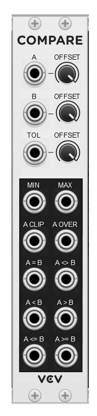
Proposed Inputs

An offset knob would be added to A, functioning the same as the B input.

B inputs/knob would stay the same (though different layout)

The critical addition is the TOL (tolerance) input and offset knob. The tolerance would be used for all computations except MIN and MAX. This is equivalent to specifying the size of the window for a windowed comparator.

All inputs would be normaled to 0V, and all offset knobs would range from -10V to 10V.

Proposed Outputs (I will use T to represent the tolerance value):

MIN - Minimum of A and B (no change)

MAX - Maximum of A and B (no change)

A CLIP - The value of A, clamped to within B +/- T.
This can be computed mathematically as: Min( Max(A, A-|B|), A+|B| )
This is basically the same as the existing CLIP, except now B is the offset from zero, and T is the tolerance. To get the old computation, patch the old B value into TOL, and keep B at 0.

A OVER - The amount that A overflows the CLIP constraint, computed as A - CLIP * Sign(T)
For the old behavior of the top LIM, do the same as for CLIP, but make sure the TOL is positive. If it is negative, then it will invert the output.

A = B - Output 10V gate if |A-B| <= |T|, else 0V.
This is equivalent to old bottom CLIP if patched as described for A CLIP.

A <> B - Output 10V gate if |A-B| > |T|, else 0V
This is equivalent to old bottom LIM if patched as described for A CLIP.

A < B - Output 10V gate if A < B - |T|, else 0V
Same as old output as long as TOL = 0

A > B - Output 10V gate if A > B + |T|, else 0V
Same as old output as long as TOL = 0

A <= B - Output 10V gate if A <= B + |T|, else 0V

A >=B - Output 10V gate if A >= B - |T|, else 0V

Granted, many of the outputs above are easily computed from others, but having everything in one module provides a number of benefits:

  • Less CPU (fewer modules needed)
  • Smaller footprint (good as long as not too crowded)
  • Easier to keep divergent signal paths in sync down to the sample level (this is a big one for me)

I’d love to see this implemented within the VCV Fundamental plugin. But I think it would be worthwhile in any plugin - I don’t think there is anything else with that level of flexibility at the moment.

EDIT

I actually implemented a version of this in my Venom plugin WINCOMP module

7 Likes

That sounds like a great module, but probably advanced enough to be it own thing :slight_smile: I see what you mean with LIM, it might not be perfect, it’s intended as “limited content”, but I think using the term “over” would be misleading because it also outputs the content of A when it’s UNDER -B

1 Like

Yes, the concept is easy to visualize in my head, but hard to come up with terse, yet unambiguous and clear language. I don’t think I have succeeded yet.

When I think of overflow, I am considering the magnitude (absolute value). In the programming world the concept of overflow is a natural fit. Integer (or floating point) arithmetic may overflow in either the positive or negative direction. But I can see how that language might not be intuitive for the average person.

I struggle with “limited content” because both the CLIP and LIM have limited content. Actually the CLIP has a true limit. The LIM output is virtually unlimited, within the constraints of the floating point implementation - it just has a hole around 0V .

Upon reflection, I suppose I prefer LIM for the CLIP output because CLIP implies to me the signal has definitely been clipped, whereas LIMIT implies the signal is constrained, which may result in clipping.

That still leaves what is currently labeled LIM. A short term (possibly an abbreviation) is needed that means “magnitude overflow”. What I really like about the term overflow is it implies a quantity, which I think is important.

Hurray! LOGIC polyphony has been fixed in release 2.3.1!

4 Likes