TL;DR version: would VCV Rack be an appropriate real-time environment to supply actual control voltages to physical hardware?
I’ve cobbled together a VCV Rack plugin that sends CV values to a Raspberry Pi. The Pi in turn interfaces to a custom board with a digital-to-analog converter, sending the CVs to CEM 3340 oscillator. I’ve got the basics working, Pi, DAC, (not pretty looking) plugin. The plugin’s process method sends current CV values to the Pi, the Pi manipulates a DAC, the oscillator does its thing. Seemed like a cool concept to me- utilize VCV Rack LFOs, envelopes, sequencers and all that; have some underlying physical hardware that just follows along with a fully analog audio path.
Ideally I’d like to send data once every few milliseconds. That should be good enough for most CV signals. What I’m noticing is that my plugin’s process gets called reliably for 1200 - 1800 samples then there is a delay of 50-100ms between calls to process. This happens once every 1200-1800 calls to process. So no DAC data during that time window. That 50+ ms delay is a bit tough to work with.
Before asking if there is a way to reduce that, I probably ought to start with is generating semi-real time CVs a use case I should consider for VCV Rack? And yeah I know the caveat that neither the Pi nor the Rack host I’ve got are real time systems to begin with. If this might be workable, what might I try to minimize any delay for a plugin?
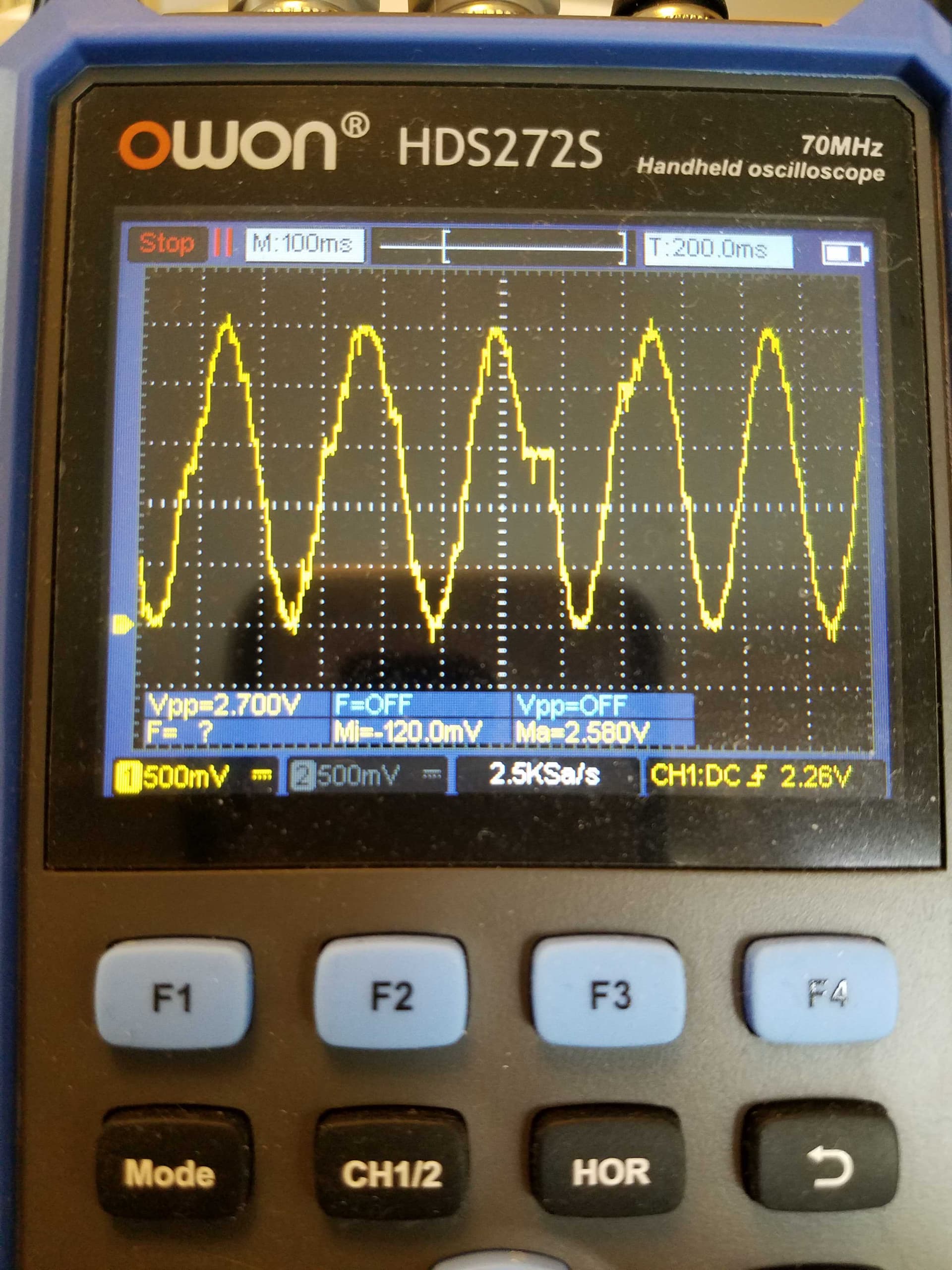
Here’s an oscilloscope shot of DAC output. This is coming from a ~5 Hz VCV Rack generated LFO wired to the plugin I’ve got. Looks decent til you get to that flat spot in the middle where process doesn’t get called.
What do you mean? A module’s process gets called without hiccups, otherwise you’d get audio cracks etc.
The problem probably lies in the way you send the data to the PI or how the PI outputs it. You haven’t said much about how that is done so it might be hard for people to help.
I heard many people use Rack with hardware using the Expert Sleepers CV interface and noone seems to complain about such “hiccup issues”.
FYI you can run Rack directly on the PI as well thanks to the Sonaremin project.
Doing some more RTFM’ing and I’m coming to similar conclusions that my plugin is too naive, and that process() ought to be treated like an interrupt handler, handing stuff off for processing. And when I say naive that’s pretty much exactly what this plugin’s process() logic is right now: if a value hasn’t been sent in the last 2ms, call sendto(). I’m gathering I ought to be surprised it’s actually working this good given my lackadaisical system calls in there.
So a more correct approach would be to just track current values in process(). Then have a thread wake every few ms to do the system call, sending data to the server. I’ll try that out.
Thanks for the tip on the Sonaremin project, I’ll have to take a look at that. Running Rack locally would be pretty cool!
I played around with having process() update a store of current CV values (along with a boolean noting it’s been updated). A separate thread loops forever: write a system timestamp & the CV values to a file, clears the boolean, then sleeps for a microsecond.
Even with the thread added what I’m noticing is there are quite a few milliseconds where CV data is not updated. I think it’s related to blocksize & along with my naive implementation. With a small blocksize I see fewer instances of data not being updated. Large blocksizes and not much data is ever current.
I’m guessing what I need to do in this module is buffer a couple milliseconds, at least a blocksize worth. Basically emulate an audio device; request a block of data instead of being spoon-fed one sample at a time. Which kind of makes sense since this is outputing to a hardware DAC at the end of the chain, I’ll need to come up with the analogous device driver.
I wasn’t familiar with the Expert Sleepers module, I took a look. It’s connected via SPDIF, which is going to have an underlying driver for it. Any buffering and such would be handled at a lower level than the module, by the SPFDIF driver itself. That lifts the buffering burden from the module. Smart. Looking at their github repository confirms the code isn’t doing any threading or buffering of samples; it’s not an overly complex module. Makes sense.
So I think my next step here would be to determine what sort of buffer size I need and how much latency I ought to introduce. I think it’d be related to the blocksize / sample rate being used.
Think I need to back out on this a bit; not surprisingly looks like this has been solved elsewhere. Seeing this from the development blog from ~2 years back:
Added fix suggested by @stoermelder to allow plugins to register their own audio/MIDI drivers. For example, it will be possible to create a plugin that installs an audio driver that communicates with an Arduino over a serial connection and exposes CV as a 1000 Hz audio interface. You will then be able to select the “My Custom Arduino Protocol” driver in VCV Audio, and it will handle resampling as needed. Or, register a MIDI device that converts MIDI CC messages to/from your custom Arduino protocol. I’m sure there are many ideas the plugin developer community can invent with this API.
I’m guessing that’d be the way to go before I reinvent the wheel. Looking to get more info / examples / documentation on that.
1 Like
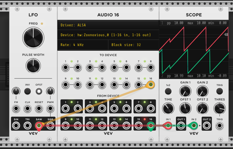
Well this certainly looks promising: setup a Pi as an audio gadget using the g_audio module. I configured with 16 channels (I’ve not tried more) and a low sample rate of 4 kHz.
To see if it works: run alsaloop on the Pi while a host runs VCV Rack. And here’s how CV data looks roundtrip. Patched an LFO to the Pi and read the same data back from the interface. So what you’re seeing on scope should be roundtrip latency. Seems workable.
I think something like that ought to be sufficient. I’ll take a look at core Audio module as a starting point and tweak from there.
2 Likes
Very nice! @Jens.Peter.Nielsen was looking to do something similar and I also ended up looking at the suggestion from Andrew of an audio interface and suggesting that to Jens. Interesting project, keep us posted.
PS: With Nyquist and all, shouldn’t it be sufficient to keep the samplerate at 2x + a bit of the highest desired CV samplerate? So if you want to transfer CV, say an LFO up to 100HZ then a samplerate of 300HZ should do? Dunno, I never fully understood Nyquist and how you end up with accurate waveforms 
Re: Nyquist. You’re not going to like a 100 Hz sine wave reproduced with 3 data points (300 Hz) for an LFO.
That’s what I figure, so I don’t know how it works for a 20KHZ wave at 44K samplerate - like I said - I don’t really fathom why Nyquist works for audio. Anywho…
What do you reckon is the minimal, acceptable samplerate for a 100HZ sine LFO? Imagine you’re doing vibrato with it on a VCO - when would it be good enough for no artifacts to be audible by humans?
That’s really outside my area of expertise and my intended scope of this thread, but since you asked… Also, a 100 Hz sine, is that really considered an LFO at that point? Tabling that one.
Maybe approach the question as “at what update rate would one not perceive zippering from a modulator?” Polysynths from the 80s used to update DACs somewhere in the range of 2-8 milliseconds. Say it’s 5ms / 200 Hz sampling rate. They produced some decent software envelopes and LFOs at that rate. Nothing in the 100Hz LFO range though. Also consider stuff like k-variables in Csound; they’re used for control values and updated much less frequently than audio rate (1/10th the audio rate I seem to recall? it’s been forever ago I used Csound. may not be current).
If I can get in the range of 1-3ms per update out of this and the latency is decent I’ll be happy. I’m well beyond my scope of expertise here in pretty much this entire project. Lots of hardware designing/hacking/soldering. Having fun at it, so that counts.
Now, if I can get the Pi to setup as both an audio gadget and a midi gadget simultaneously that’d be a trick. So far I think it’s either one or the other. And that’s definitely outside the scope of this thread.
1 Like
This looks promising. Is the audio output DC coupled?
you do need to filter out the resulting “stair steps”. In audio that would be called a “reconstruction filter”. After all, you don’t want your CD player (back when they existed) to put out stairsteps with harmonics up to Infinity!
For a practical example, look at my ancient “LFN” module. It runs at 1/200 of the audio sample rate, then uses a one pole filter to smooth it out. The result? a graphic equalizer and noise generator that take virtually no CPU. done!
1 Like
yup, it’s a PCM stream of samples. No digital capacitors to block DC