I’m wondering if anyone might have suggestions on how to provide an intuitive interface for patching physical components in VCV Rack. I realize I’m going off the deep end with this but here’s the setup…
I’m developing hardware that can be controlled in VCV Rack via a plugin & modules. The hardware generates analog signals, and has decent but limited routability between physical boards. The big idea being VCV Rack provides the control voltages along with a set of modules to provide a facade to each hardware board; the audio path is completely analog.
Towards the actual patching between boards, this is done in hardware with analog multiplexors. Switching the muxes is controlled through a VCV Rack plugin. This is where things start to deviate from the Rack virtual world since the hardware can’t do the any-patch-point-to-any-patch-point you’d have with typical Rack modules.
My first approach on this is to have each module with knobs or buttons to select which other module it’s patched to. It’s not the patch cord / VCV Rack way but easily-ish doable. A downside is it’s not visual like patch cords on the routing. Another side effect is none of the modules have Output jacks, since the module uses knobs/buttons to tap other inputs (ie- turn the knob to select which physical signal to tap into).
Another direction might be to have Output jacks and actually create routing through VCV Rack patch cables. This seems frought with issue- each module would need rules on whether that’s a valid patch or not, and virtual VCV jacks couldn’t patch to an (intended) physical analog jack. And even among the physical boards not all routing is possible; rules for where one could patch are needed.
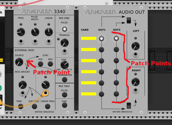
I’m wondering what one might expect to see in the UI for crossing the gap between the virtual an physical worlds here. Screenshot of how the first idea is shaping up. The called out patch points are where each module are using muxes/switching to select signals from other boards.
One idea that comes to mind is symbols and colors. If there are a fixed number of routes you could create a symbol and color for each. So like a red start and a yellow moon. Thenv you could draw the corresponding symbol at each end. Just a thought.
Your also ask what people might expect. Is the anything else similar to this that you can find? That might be a good place to look for inspiration.
Good direction, and thanks for the idea. Yeah- having a UI widget on both ends with some info to highlight the to/from. Basically a patch cord but not an actual patch cord; a mnemonic instead
Thanks for bringing it up here @Jens.Peter.Nielsen, now I recall seeing that and the EMS Synthi. yeah- that would definitely set the bar for visualizing something like this. Having a separate module where the sole purpose is to highlight the routing- I like it. I’m a bit daunted at the paradigm shift: where currently I’ve been thinking the “business rules for patchability” would be in each module; this may change that so a separate routing module would have the patching rules. But I asked for UI ideas, not on implementation and you highlighted a very flexible way to visualize the patching.
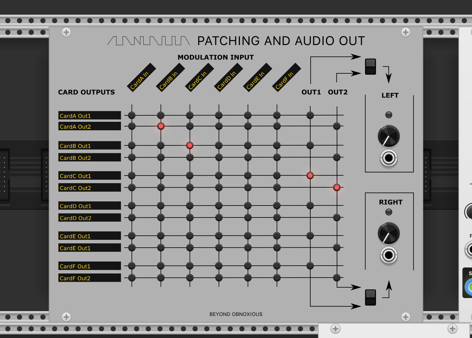
Mock up of what this could end up looking like. I like how this represents the combination of the virtual & physical side of things: VCV Rack cable patching for control elements and the analog signal routing via the patch matrix. Curious what others might think as I’m flat out awful with UI.
The text ought to be dynamic based on what physical hardware is present. The shown “CardA Out1” is not descriptive. “3340 Pulse” would be better. Even better would be “3340 Pulse (1)” to allow for multiple instances of the same hardware card.
And the patching is not likely to be a complete matrix as shown; the hardware I’ve got will limit some of the patch points. So some columns will allow only 1 or 2 patched selections (ie- allowing only 1 the column acts as radio buttons).
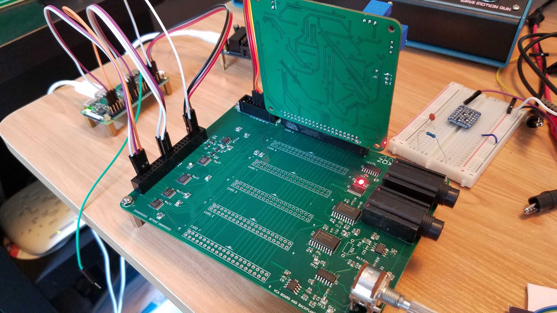
For context and to show the hardware geeks, here’s a picture of the backplane I’m working on that will hold 6 cards. The vertical card is a 3340 oscillator board. It’s got a Raspberry Pi Zero jumpered right now; the Pi will mount on the board where it’s jumpered to after some more testing.