Timing of clock-dividers

Trying to get my head around clock-dividers from a development point of view. Perhaps I am trying to “trip my own legs” (make it more complicated than it should be), as I would like the divider to react in the same way whether the input is a trigger or a symmetric square-signal.

Clock-dividers for even divisions at exponents of 2 (2, 4, 8 …) are very easy to implement. A full clock-cycle consists of a “high” and “low”-phase (e.g. written as “10”). Hence a “/2” divider should toggle its high/low-state each time the module receives the base-clock input (e.g. detected as a “clock” going high using a dsp::SchmittTrigger). Likewise a “/4” divider should toggle its high/low-state each 2nd time the module receives a clock-input (or each time the “/2” toggles to high). So whether such a module is fed an input-clock in form of a square-waveform or each “clock” is a 1 ms trigger, the module would work, as it simply have to “count” the number of times the input goes high (hence using a dsp::SchmittTrigger). For that matter the input could be a manual push button, as it simply have to “count” the number of “going-high” signals.

Clock/1: 101010101010 (1=High, 0=Low)
Clock/2: 110011001100
Clock/4: 111100001111

But for any other division (e.g. “/3”) I can’t see how to do it simply “counting” the number of input-clocks. As I see it, the only way to implement a “/3” divider (or any other odd-divider) is to measure “the time” (number of cycles) between 2 successive incoming clock-signals? A full clock consists of a high-phase and a low-phase, hence the base/input-clock could be seen as “10”. A “/2” division could then be seen as “1100”, so as written above, simply toggle between high/low each time the input-clock goes high. But a “/3” division if seen as “111000” should stay high 3 times as long as the base clock is high (as long as the input is a symmetric square). So to also support input’s as triggers, first measure “the time” (number of cycles) between receiving two input-clocks, so we have “the time” of a full clock cycle. Then divide this by 2, in order to know “the time” of the high/low-phases. Finally multiply this by 3, so we know for how long time our “/3” should be high (and naturally it have to be low as much time afterwards) ?

In stead of measuring “the time” of a full (high/low) clock-cycle, you could measure the time the base/input clock is high (half a clock-cycle). But in that case it would only work as long as the base/input clock is a symmetric square-waveform, hence it would not work if feeding the input-clock with trigger-signals, and I can’t see that this would work with a manual push-button, as it is no longer about the “count” (number of times input is “going high”) but is all about timing?

Am I totally wrong? or is there a another/better approach than “keeping track of time” (between successive clock-inputs), hence needs to have received two input-clocks before being able to calculate the correct timing for odd divisions?

I’m guessing the same method (time between 2 base-clock) would have to be used if you want to have a module that can multiply clocks. E.g. to output a “*2” clock (double the frequency of the incoming base-clock), you need to have received 2 input-clocks before you know “the time” a base-clock takes, as the “*2” should take half the time?
2 Likes

It’s easy for any integer. You can just count clocks, you don’t need to measure the time between clocks.

In fake c++:

if (inputClock) numClocks++;
if (numClocks > x) {
     dividedClocks++;
     numClocks = 0;
}
1 Like

To turn a stream of triggers into gates, run them through a flipflop.

In stead of only counting incoming gate-high wouldn’t I have to count in stead the number of times the incoming signal toggles between going low-to-high and high-to-low?

/1 = 101010101010101010101010
/2 = 110011001100110011001100
/3 = 111000111000111011100011
/4 = 111100001111000011110000
/5 = 1111100000111110000011111
/6 = 111111000000111111000000

First line is the (incoming) base-clock, and if generated by an LFO with a frequency of 1 Hz, a full clock-signal will be 500 ms of gate-high followed by 500 ms of gate-low (hence 1000 ms between each clock signal). However in this case shouldn’t a “/3” division then consist of 1500 ms gate-high, followed by 1500 ms of gate-low?

I can’t follow all that, but it sounds like you are concerned with when the output goes from high to low. It doesn’t matter. It’s triggers that matter, not gates (usually).

If you’re looking for a method to perform an odd division but keep an equal mark/space ratio, have a look at VCVRackPlugins/src/inc/FrequencyDivider.hpp at master · countmodula/VCVRackPlugins · GitHub which is what I use in my Voltage Controlled Frequency Divider MkII. Note, my other dividers simply use a count and preserve pulse width of the clock.

And before Squinky reminds me, I know it does not have any anti-aliasing yet.Oversampling is on my list of things to do. :smiley:

2 Likes

I’d suggest taking a look at the manual for the Doepfer 1-160-2 Clock Divider 2 module: A-160-2

What you are describing is similar to the A-160-2 “gate” mode. It think what it does is look for the falling edge of the incoming clock to know when to flip the odd-number divisions.

As to your actual question, I agree that in order to make a “gate” clock divider that always outputs a 50% pulse width signal (regardless of the pulse width of the input clock signal) your module would have to calculate the high/low times for all the reasons you identified.

1 Like

yes, all that is true, but I’m pretty sure that’s not what OP really wants to do. I think they just want to make a “normal” clock divider, which a) is not always the same duty cycle as the input, and b) is trivially easy to make.

@Squinky as I started out, I am perhaps “tripping my own legs”, and trying to make it more complicated than it have to be. Yes my goal was to generate output where each division would output as a symetrical-square (equal high/low-time), so this is where the whole “timing issue” is rooted. Hence the need to know the timeing (or count edge-changes), in order to know the “length” of the high-phase, which for odd-divisions would “end” inbetween two clocks of the base-clock. If simply outputting odd-divisions as triggers it’s true I could simply count the number of input-clocks.

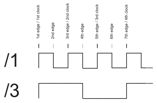
I clearly failed with my 0’s and 1’s (and my poor description). So I generated this image to perhaps better show what I’m trying to achieve: Div3rd

@CountModula I had a brief look at your source and I can see your gate.anyEdge() is detecting both leading- and trailing -edges. So instead to having to deal with timing’s betweeen clocks (which could be “interesting” in itself, with dynamic clock-rates), I can simply count the “edges” of the incomming clock. A “/3” high-phase will begin at the same time an input clock (“/1”) is received, and it will stay high until 3 edges are received (1st edge started the cycle), so the “/3” goes low when the base-clock goes low for the 2nd time (3 edges), and then simply 3 more edges for the “/3” to ends it cycle. Doing so, if the input-clock is symetrical, so will the division-outputs be. If the input clock is not symetric the divisions will not be either, but at least the divisions will go high at the correct time, and there can’t be any drop-outs (no matter how fast the rate of the input-clock is changed) which is the most important aspect.

@computerscare Thanks for the link, will have a look.

However gentlemen (I assume) when it comes to clock-multipliers, can you see any way to implement that, other than meassuring time between 2 succesive clock-inputs. E.g. a “*2” clock would every 2nd time fire at the same time as the base-clock, but you would also have to fire it “between” input-clocks (a “*3” clock would have to fire twice between base-clocks). Going down the “timing-route” would only “work” as long as the input-clock is steady. If the input is slowly changing, there would be a “timing issue” with the “in between” clocks (generate clocks between the base-clock signals), whereas if the input-clock is changing rapidly you could end up generating too-few/many inbetween clocks (e.g. with a “*4” clock-multiplier, if the base clock changes by more than 25% “it won’t be pretty”).

1 Like

Yes, if you really want the output to follow the duty cycle of the input (in your example 50%), then you do need to measure the period, as you and others have said.

Most clock dividers don’t do that.

Enjoy!

1 Like

@computerscare Had a closer look at the doepfer-link and I was actually trying to do something similar. In this small snippet of my panel (starting out as a concept-design in InkScape), I’ve placed a small Red/Green-toggle button next to each output where green=gate, red=trigger (here both /2 and /4 are set as trigger-outputs). The small buttons next to Clk/Rst is to fire these manually:

DivPanelTop

1 Like