+1 for Jens’ suggestion, I use it often and does the trick.
Who wants to hear about a more convoluted solution? Anyone?.. I’ll take your silence as a yes.
If for some reason you can’t use the above module in your patch (whether it’s due to self-imposed restrictions or you’re taking on a challenge that limits module selection), here’s a fundamental-only trigger buffer :
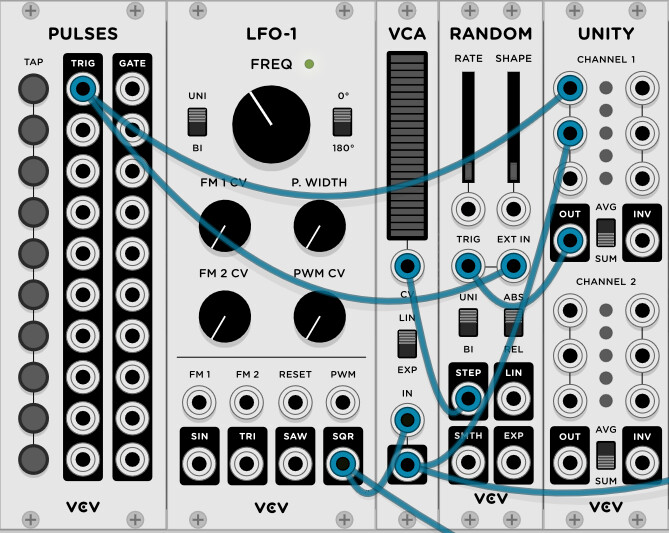
Came up with this as I was working on the latest “Day of the Dead” contest (which was filtered down to VCV Fundamental, Vult and Geodesics modules). Just make sure you use triggers throughout, not gates. It works as follows :
The trigger coming from PULSES is what you’d consider your “advance” button (this can be replaced by any other module that sends trigger signals)
By going through UNITY, it triggers the S&H of the RANDOM module. Since the trigger itself is also used as the external input, RANDOM holds on to a 10V value. This is the latch.
This value opens up VCA, which will let through the next clock signal (coming from an LFO-1 with PW brought down to 1% in this case, but which you could replace with Clocked)
When the clock signal goes through the open VCA, you can use the VCA’s output to wherever you need in your patch to bring about any changes that you want.
At the same time, the clock signal that the VCA lets through is also being sent to UNITY and then to RANDOM to trigger another S&H. This time, RANDOM will hold on to a 0V value because no voltage is being fed to the external input, thus closing down the VCA once again, severing the latch.
Here’s a little patch to showcase this. Simply tap PULSES and when the next clock signal hits, the trigger goes to a sequential switch module, causing the VCO to alternate between two notes.
Man I’ve been "rack"ing my brain trying to design a trigger buffer, but could never get it right. This is brilliant, so simple yet effective. Nice one @Loops
Clever - I like it. The S&H was not an obvious choice, but it is effective. But this only works when the clock is a trigger.
If the clock is a gate and the pulse happens in the middle of a high clock state, then the pulse is sent immediately - it does not wait until the beginning of the next clock high state. When I first tried to replicate your patch, I missed the LFO “clock” PW setting, I used the default 50% and of course it did not work properly. But setting PW to 1% is effectively a trigger, and thus works.
Also, the advance button must also be a trigger and not a gate, else a single advance pulse can trigger multiple pulses if the advance gate is held high.
The ML Trigger Buffer works well equally well with gates or triggers for the clock and/or the advance button.
While there are plenty of free ways to do this, just wanted to mention that ShapeMaster Pro can do this too when it is in Sync mode with lock on. The lock essentially quantises all trigger inputs to the beat (or whatever the cycle length is)
So if you send a manual trigger to the T/G input, and have a simple gate shape, the manual trigger will be treated as early and the gate output will be quantised and fire on the beat. You even can be slightly late (there is a something like a 100 sample grace period).
Good point, I should’ve mentioned in my post that you need to stick with triggers, not gates (for both the clock and the latch) if you want it to work well.
Even then, I admit my little patch is poorly tested and surely people here can find more ways to break it. It just happened that when I used it in my patches, it did the job
It is not particularly hard to transform a gate into a trigger using VCV Fundamental modules, so Loop’s solution can be used with either triggers or gates.
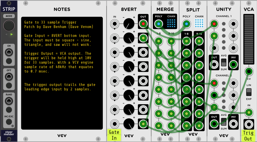
Below is a picture of a simple gate to trigger strip. The labels are not included in the strip.
The UNITY Channel 1 functions as a logic NOT gate, and Channel 2 coupled with the VCA is an AND gate. The VCA screens out negative voltages, so the AND output is always 0V or 10v. The 8VERT provides constant -10V and 10V CV needed by the logic gates. The MERGE and SPLIT function as a 33 sample delay.
The incoming gate is sent to both the AND gate and the 33 sample delay. The delayed signal then goes to the NOT gate, and the result is then also sent to the AND gate. Starting with the gate signal low, the NOT input is high, and when ANDed with the low gate, the result is low.
When the gate goes high, the non delayed AND input immediately goes high, coupled with the high NOT results in a high output. After 33 samples the NOT input finally gets the high gate, resulting in a low output, that forces the AND back to a low state. Note that at 48kHz, a 33 sample delay equates to a 0.7 msec trigger.
Here is Loop’s delayed trigger patch after it has been modified to work with gates. It uses the PULSES gate output instead of a trigger, and the LFO “clock” PW is set to 50% so the clock also becomes a gate. I then use a couple instances of my strip to convert the gates to triggers, so Loop’s original design can work.
fundamental gate buffer.vcv (20.0 KB)