Squinktronix Phase Patterns discussion thread

Again from @john_rose .

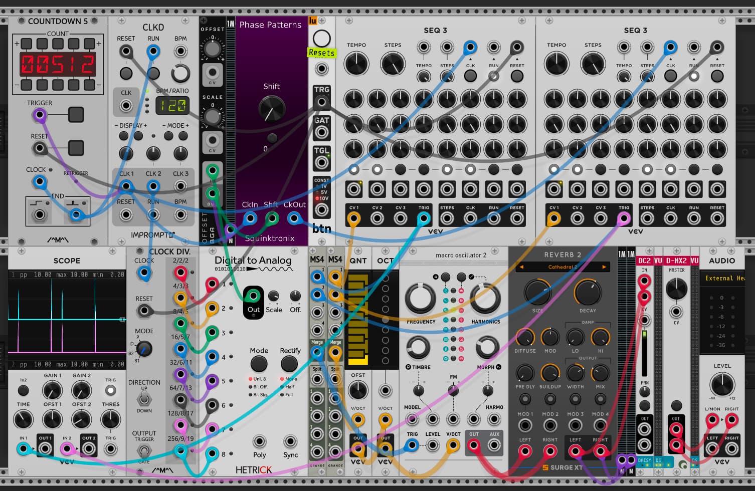
"It would be neat to make it repeat indefinitely, and to be able to select much longer (more than 8 beats) patterns. [much later, crawling out of the rabbit hole] Ah. Used Hetrick’s Phasor Generator set to a very low frequency, scale its output to 0.1, and plug that into the Shft input of Phasepatterns. I got patterns over a minute long. "

Yeah, got any specific suggestions? ATM it’s “shifts by one clock after 8”. more general of course woud be “shifts by ‘n’ clocks after ‘m’”. Would even be nice if ‘n’ were not limited to integers, so you could shift by half a clock…

I don’t want to turn it into an unusable “does everything”, but clearly it’s too limited now. And of course you can (in theory) feed stuff into the CV input an make your own… Along with this - the CV, at least by convention, is limited to 0…10V. But what if you want to delay by more than 10 clocks???

“Just gotta set the clock bpm to be some multiple of the Phasor frequency such that when the Phasor wraps around from 10V back to 0V you’re not in the middle of a clock cycle. This can be a fun module, being a big Steve Reich fan myself.”"

Well, I can’t wrap the “real” value from 10 to 0, because 10 really is 10 clock delay… Oh, on second thought, maybe I could do that…

“One feature to add might be a zero-delayed clock output normalled from CkIn, just so you can easily trace the two clock signals back to the one module, for a tidier-looking patch.”

It would be impossible to do that. Modules always have a 1 sample delay, I can’t do anything about that.

“I just noticed this: The name on the panel is “Phase Patterns”, The manual calls it “Phasepatterns”.”

Yeah, I changed the name to “Phase Patterns”. Clearly I didn’t update all occurrences, tx!

Oh yeah … I made a “fencepost error” there, but I’m not sure it matters that much for really long-duration interference patterns.

…and…

I changed that. PHASOR GENERATOR is out. Now (in my test patch) I’ve got the main clock going to Count Modula’s CLOCK DIV, those 8 outputs go into the 8 inputs of Hetrick’s DIGITAL TO ANALOG, that output passing through Bogaudio’s OFFSET (for the scaling), and then that output into PHASE PATTERN’s Shft input. That way I can independently change the length of the timing with either the CLKD’s multiplier/divider knob or the Scale knob of the OFFSET module, and any transition from 10V back to 0V will occur on a clock pulse. It doesn’t fix the fencepost error, but I could always add some logic (an 8-input AND gate plus one logic inverter for the 8th bit?) that resets the CLOCK DIV one click earlier. At (or just after) binary 11111110, I think. I might need a sample delay or something somewhere. Plus time for my coffee to kick in. It (the bunch of AND gates) could be adapted to giving pattern lengths of arbitrary numbers like 37, and not just powers of 2, but then I need to do arithmetic the figure out how much to scale the ramp going into Shft so that it starts/ends in integer values.

I was able to make a pseudo-Reich patch (that rabbit hole) using two SEQ 3 modules set up to play a four-note melody “C D - - D C - -”, and the phase pattern repeats in about 1 minute 35 seconds with CLKD set to 120 BPM. Now the fun part will be making it work with three or four “players”

Ooh - I can use Count Modula’s COUNTDOWN 3 instead of the octal AND gate. For figuring out the scale value, I had better educate myself on the care and feeding of BASICally to do it automagically after I type in the COUNTDOWN 3 number.

See what you’ve gone and done? Rabbit hole!

Here’s what that pseudo-Reich patch looks like. In both SEQ 3 modules:

  • CV2 and CV5 are set to 0.167 (a “D” note).
  • All others are set to 0 V (middle C),
  • only triggers #1, 2, 5, and 6 are enabled., for the “da-dum, dum-da” rhythm

Main clock:

  • CLKD is set to default 120 BPM
  • CLK1 to 4X
  • CLK1 to 1X - adjusting this one is one way to lengthen or shorten the pattern without affecting the tempo
  • At 512 CLK1 ticks it stops, with both SEQ 3 modules in synch.

If I disconnect the END trigger output from COUNTDOWN 5 the pattern repeats and runs indefinitely.

Oh yeah. If I move COUNTDOWN 5’s END trigger output to the CLOCK DIV’s Reset, and change the number to 511 (I think?) it should get rid of the fencepost error in the Shft voltage between indefinite repeats.

I have to confess this is getting a little over my head… But hopefully it’s saying that this relatively simple generic module can do some cool things when it plays with others :wink:

just come back and tell my what more to add or change :wink: Also, it the “fence post error” you refer to what happens when you take the CV from 10 to zero? I guess you would want the accumulated 10 clock delay to stay around, rather than disappearing? It give me a weird feeling - esp since I tried something like that and the whole delay would go away… details are foggy… ]

It still seem like one way or another you want to be able to get more than 10 clocks delay from CV…

Oh, should the RIB button also have a CV? Seems difficult to get that “reich in a box” without using that?

Anyway, when you have to some time, let’s condense all this (hopefully) into a plan for the next version.

It’s like what my sons call “emergent gameplay”

Also, it the “fence post error” you refer to what happens when you take the CV from 10 to zero?

Uh… I guess? I’m talking about the notion of calculating the number of fence post required for a fence. Say you want fence posts 1 meter apart, and the total length is 10 meters. The quick answer might be 10 posts, which is wrong, because you need an 11th post to hold up the far end. Conversely, for a circular fence of 10 meters circumference, you might be thinking of that earlier calculation, and buy 11 posts, because that’s how the hardware store bundles the package. This is one extra, unless you make it 11 m circumference. A similar thing can happen in animation of a rotating object that has an extra frame, because the first and last frame are the same view.

I guess you would want the accumulated 10 clock delay to stay around, rather than disappearing?

I don’t see what you’re getting at there, as long as the intervals between the original clock are all the same. If it’s a steady 120 BPM, that’s an interval of 0.5 seconds. Chop out, say, 10 beats (or 5 seconds), the surviving intervals are still 0.5 seconds apart.

If it was a clock with swing added, or from a Euclidean rhythm generator, then I could see trouble happening. In that event, put Phase Patterns upstream of those components. :thinking: I think that should work.

It still seem like one way or another you want to be able to get more than 10 clocks delay from CV…

Well, didn’t I get 511 unique delays (or intervals) in my sample patch? I’m not sure I really understand what you mean by “10 clock delays”.

I’m only interested in fractions of a single interval, since all intervals are the same. I could get many more unique intervals, although at some point I might have to double up on the CLOCK DIV and Digital to Analog modules, feed them alternating pulses from a flip-flop, and sum the outputs for double the resolution (to 16 bits) of the output ramp. The flip-flop is so that they don’t both increment on the same clock pulses.

Oh, should the RIB button also have a CV? Seems difficult to get that “reich in a box” without using that?

Maybe something like two boxes to enter numbers into. One for the number of clock pulses for the duration of the pattern then a second one for how many pulses (a smaller number) you want to stretch out to the same time. It would be rather like how EUGENE has a “Length” selector and a “Hits” selector.

Except that Phase Patterns would spread them out evenly with equal intervals, say 7 pulses for every 8 clock pulses, or 73 for 80, and not simply skip them. That would really save users from having to do a lot of arithmetic to get a desired outcome, and predict when the pattern comes around to both clocks being in synch again.

The number entry could be like how Count Modula has the add/subtract buttons above and below the red LEDs in COUNTDOWN 5. Probably 4 digits (on two display pads) would be plenty though. No need for 7-segment digits either—simple smaller numbers (like EUGENE’s) would do just fine.

And those two values could be selectable by CVs. I have no idea how you make Phase Patterns work in the first place, so I have no clue about how hard that is to make happen, nor what kind of performance hit it would cause. My ignorance is bliss.

1 Like

I’ve found out that Phase Patterns works very nicely with Geodesic’s IONS, using the normal clock to drive the Blue sequence and the phase delayed clock to drive the Yellow sequence. Both set to use only their own LOCAL CLOCK. Make PROBABILITY 0.5 (=50%)

2 Likes

we are not thinking about this the same way.

to me, 2 sequencers start of playing:

abcdefg abcdefg

then, one gets a whole clock behind the other

abcdefg xabcdefg

Then two clocks:

abcdefg yxabcde

being one clock behind is not the same as being zero clocks behind.

Now, that said it could work that way. As it happens it doesn’t work that way, and terrible things happen when you go from 10 to 0. But ignoring that, say it did what you expect. What would the display show? It’s actually useful now - it shows you how many clocks have slipped since the start.

Say it was displaying 10, because you are in fact 10 clocks behind. Then you give it one volt input - so it goes to 11. But what should it display? 0? 1? Well, the display can go as high as it wants, so that’s ok.

But what if you increase the voltage in to 10, so it’s 10 clocks delayed. You can’t delay any more from CV, because CV isn’t “supposed” to go over 10. and even more important, what if you were delayed by 10 clocks, but it was displaying 0? Then you want to catch up. But Phase Patterns doesn’t let the CV go negative, so you can’t.

I think it’s important to consider what happens if you want to delay more than 10 or less than zero.

I’m sure there are ways to make it work how we would like, but we first have to define what that means.

Does that makes sense?

Oh. In that example I would call it “one step behind the other” and “two steps behind the other”. If, in the example of abcdefg & yxabcde, step “a” ends up starting at exactly the same time as step “y” (and “g” coincides with “e”), then isn’t the clock difference (tempo and phase) effectively zero, from the point of view of the sequencers? :thinking:

probably. I think I’ve been stung by cases where that is all true, but they didn’t end up the right number of steps behind each other. for me it’s super important to make it actually work musically. I know they aren’t incompatible…

To answer your specific question - sure shifted by a clock, the input clocks look the same. But something happened such the that step number of the sequencers are different. different by one. It would be easy to make a clock shifter where they were not different by one, but were different by zero. Or by two.

So here’s my Phase Patterns Use Case:

Use a sequencer of some sort to generate triggers for a drum.

Route that trigger into the clock input of Phase Patterns.

Use a logic OR like Submarine OG-104 to merge the original drum trigger with the Phase Patterns output.

Tweak shift and duration etc. You get a drum pattern with interesting flamming added. Also you can use the drum gate through a bernoulli switch to turn on RIB+ and/or RIB-.

The result can be super subtle or crazy, but because it’s a correlated timing shift it mostly adds up, but also sounds complexified in a musical way.

1 Like

oh, nice technique with the or!