First of all…
I guess there isnt really a Category in the VCV Rack forum to share info on the more theoretic bits? So I ended up in the lounge, where ‘anything goes’…
Would be nice to have a separate category on synthesis techniques and theory. Some knowledge of the more gory details is pretty usefull (and often inspiring). E.g. stuff about the various synthesis techniques and their effects on the spectrum or the relationships between the ‘wave shapes’ and the related ‘spectrum’. Audio synthesis is often pretty much about manipulating one or the other. Changing the wave shape, changes the spectrum. Chnaging the spectrum, changes the waveshape.
Anyway…
On changing a specific type of waveshape: the Modulation of the Width of a Pulse.
For many PWM might just be a knob or slider on a synth or oscillator. But many will know that Pulse Width relates to the ON and OFF time for a single duty cycle (e.g 50/50 or 40/60 or 20/80). Since the both percentages will always add up to 100%, we can just pick one to describe the width (e.g. 50%).
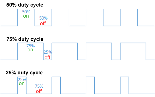
Modulating the Pulse Width is a pretty recognizable due to the ‘phaser’ like change in the spectrum, related to the pulse width. Though it is also very usefull to ‘set’/‘select’ a specific static width (to get one of the many.many resulting spectra)
But…what is the actual spectrum for a given pulse width / duty cycle?
The many words below assume a mathematically perfect binary pulse: at any point either fully ON or OFF (at some static amplitude/gain level).
Yes, in the ‘analog’ world, this ‘perfect’ shape is actually pretty uncommon…so it most often will look different and thus will sound different as well…but we’ll assume we have ‘digitally’ perfect squares/pulses here.
Simply put a ‘perfect’ pulse will have a spectrum comparable to a ‘perfect’ SAW. Where the amplitude of each harmonic is 1/rank (1=100%, 2=50%, 3=33.33% etc). But, other then for a SAW, for a PULSE, every 100/pulsewidth harmonic is missing. At least…as long as 100/pulsewidth is an integer…
So at 50% every 100/50 = 2nd harmonics is missing. At 25% every 100/25=4th is missing etc.
But…for any non-integer ‘interval’ it is more complicated. We get more or less the spectrum resembling phase shifted saws. A comb filter / phaser effect like spectrum (sort of camelback bumps spectrum). Yes…cutting corners here.
BTW, mixing/phase shifting a SAW and and inverted SAW will give you a pulse/PWM (though the offset might move off the center). Which is handy if your synth does not have PWM, but can invert a SAW. Detuning them will then give you the PWM effect. But I digress…
For anyone interested, the actual PWM spectrum for a specific pulsewidth/duty cycle:
Given:
an = amplitude for harmonic n d = 0 < duty cycle < 1 (e.g. 0.5 or 0.33 or whatever) V+ = Voltage positive (assuming V- is 0) PI = 3.1415… (approx. 355/113)
The amplitude for harmonic n at voltage V is:
an = (2/n) * (V+/PI) * sin(n * PI *0.5)
E.g. for duty cycle 50% (0.5) at 8V
We get (roughly):
a1 = 5.0V (1/1 = 100%) a2 = 0.0V (every 100/50 zero) a3 = 1.7V (1/rank = 1/3 = 33%) a4 = 0.0V (every 100/50 zero) a5 = 1.0V (1/rank = 1/5 = 20%) etc.
But for non-integer divisions it’s not that simple. E.g. at 19%, 100/19 = skip every…5.26th harmonic? Does not compute…since harmonics are integer multiplications of the first harmonic (no fractions).
This is ‘solved’ by sort-of chewing off bits of amplitude of adjacent harmonics amplitudes (crude comparison). Resulting in these wavy/bumpy amplitudes/spectra.
Some more info on Pulse/PWM and spectrum in this short document
And on PWM (various forms/implementation) on Wikipedia