While reading through wikipedia’s article on pulse-width modulation during my previous forum post, I ran into pulse density modulation as well. I figured I’d make a quick topic to see if there are modules or setups that would generate a result similar to this image, but for speech waveforms:
A rectified cosine wave (synced with a sine wave) to FM a square wave makes a simple one as in that image, similar to what I’ve done with LFOs here:
This is then about the density of pulses. The amount of individual pulses per second in relation to input signal amplitude. Not just compressing/expanding the width of a square using FM/PM).
Maybe this is actually just an AM thing over a PWM encoded signal (where the width of the pulse relates tot the amplitude of the signal, as described in your other post and the related Wikipedia article ).
AM with a SQUARE just transforms any signal in a an equal width pulse train since AM with a square will reduce amplitude of a signal to 0 when the SQUARE is LOW (0 times whatever the amplitude is at that point) and leave amplitude as is when HIGH (1 times whatever the amplitude is at that point).
Since the input is already a binary stream, it will just switch every alternating bit to 0 en leave others untouched (being either 1 or 0). o need for a comparator or something similar to maximize +/- amplitudes to binary.
The frequency of the square modulator then determines the width of the pulses.
You will definitely recognize the original input signal, since AM just causes sum and difference frequencies.
As the modulation frequency increases, the sum frequencies might (will…) soon be pushed beyond Nyquist. With aliasing as a result. Normaly, if the frequency ratio between carrier (input) and modulator (square) is not “musical”, all sort of inharmonics will appear. But…the input PWM signal is most likely already pretty messy, and this will not improve by chopping into it with AM…
In AM (unike FM) the DIFFERENCE frequencies will NOT bounce back (at inverted phase) from 0 Hz. They just sort-of ‘disappear’. So…at least one less thing to worry about.
BTW, All just theory. I have not tried any of this in VCV Rack yet.
It’s been many years since I’ve worked with high-power shortwave AM transmitters (eg 250 kW) but here’s what I recall about Pulse Width Modulation. It also works in switching power supplies.
Using the formula P=VI or “Power = Voltage x Current”, when a switching circuit is wide open, the current is high, but the voltage is effectively zero, so the power dissipated in it is effectively zero. When it’s switched off, the voltage is high but the current is zero, so again the power is zero. By controlling the width of the pulses, the voltage or power to the load can be regulated with a minimum of heat dissipation in the regulating circuit, which makes them very efficient, compared to analog circuits.
Some of the transmitters I mentioned were modulated by twenty-four 600 Volt PWM supplies in series, for a peak carrier (plate) voltage of 14,400 V. This made it real easy to reduce power as desired. The switching frequency never changed, only the width of the pulses.
That being said, since we’re not dealing with actual kilowatts of power here and sending it to some place (or thing) outside the system, I’m not sure how useful PWM is in a Rack patch.
But yeah, it could yield some interesting results. And “pulse density”, where you FM the pulse train is an intriguing variation too.
Suffice to say that PWM is one of the basic M’s in synthesizers (AM/RM, FM, PM are probably less common). Modulating the pulsewidth is a pretty recognizable ‘effect’ due to the ‘phaser’ like change in the spectrum, related to the pulse width. I might go into the actual spectrum for each duty cycle / pulse width elsewhere.
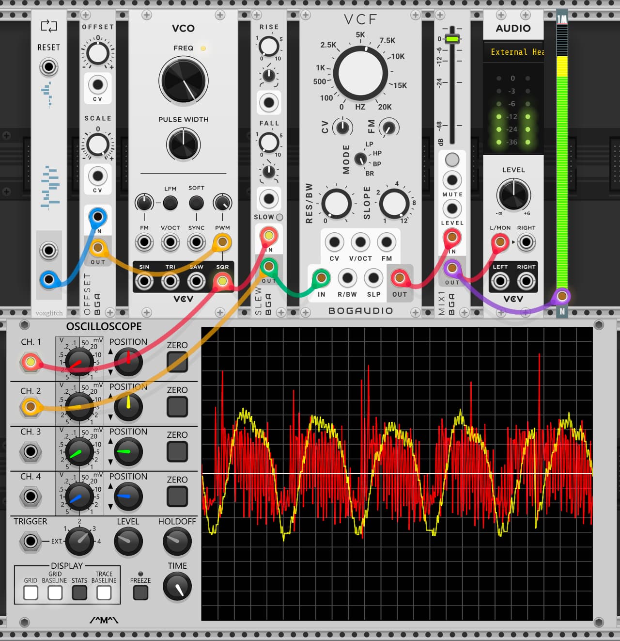
The VCF is being a tight band-reject filter to try to notch out the “carrier” frequency of 5900 Hz from the VCO. A lot of harmonics still get through though.
The demodulated audio (yellow scope trace) was recognizable speech, but it sounded like a really noisy single-sideband radio. I might use it sometime to fake a CB radio.
Signal encoding/decoding is definitively not my area of expertise…
But…very interesting. Definitively another domain to explore.
I guess many signal encoding/decoding pairs, when translated to VCV Rack, would open up all sorts of creative effects when (ab)used in creative ways. I guess mainly many ways to ‘Lo-Fi’ your signals.
Guess I need to dive deeper into more basic electronic circuitry for this sort of stuff.
More generally it’s fun and educational to actually create basic electronic circuits from basic modules in VCV Rack to learn about how stuff actually works.
Stuff like Jakub Ciupinski demonstrates in his videos, making the most of modular, with applied deep knowledge.
The Fundamental VCO has ‘analog’ waveshapes. Not mathematically perfect shapes. The ‘square’ is not square. There are also ‘per module’ differences in how fast modulation values are evaluated. So not all VCO’s do equally well at audiorate PWM.
I had much cleaner results using Befaco evenVCO, which also has a much more ‘square’ square.
With the Befaco evenVCO, I set the frequency to its max 1/16th, which at C = 8372 Hz. Also, I added a Lowpass Filter at about 5K, instead of the Band Reject Filter (and Slew limiter). The Fundamental VCF worked very well at 8K.
Silent parts in the source signal (speech) were reduced to a bit of crackle. No real audible carrier (LowPass filtered out).