I’ve been studying the excellent MI Ripples clone which offers LP2, LP4, BP2 and LP4>VCA outputs. My goals are:
- learn more about filter design / schematics
- work out how to generate other response outputs
- build an un-official Ripples v2 clone with HP2
I am not an expert in circuit design or simulation, but aspire to become more knowledgeable!
A number of resources describe how you can employ pole mixing in order to generate novel outputs:
- most relevant probably https://pichenettes.github.io/mutable-instruments-diy-archive/static/documents/pole_mixing.pdf
- Multimode filters, Part 2: Pole-mixing filters – Electric Druid
- VCV Rack VCF - BP? - #4 by Curlymorphic
Existing Ripples clone understanding
The existing clone, by @AlrightDevices uses an RK2 integrator to solve the ODEs of a series of 4 low pass cells, including resonant feedback path from the final back to the first. Source code here.
        // The 2164's input terminal is a virtual ground, so we can model the
        // vca-integrator cell like so:
        //                            ___
        //               ┌───────────┤___├───────────┐
        //               │             R             │
        //               │                  ┌───┤├───┤
        //               │           A*ix   │    C   │
        //         ___   │          ┌───┐   │ │╲     │
        //  vin ──┤___├──┤        ┌─┤ → ├───┴─┤-╲____├── vout
        //          R    │ ↓ix    │ └───┘   ┌─┤+╱
        //               ╧        ╧         ╧ │╱
        //
        //  We can see that:
        //    ix = (vin + vout) / R
        //    A*ix = -C * dvout/dt
        //  Thus,
        //    dvout/dt = -A/(RC) * (vin + vout)
Bandpass 4 pole (Warmup)
Bandpass 4 pole Summary
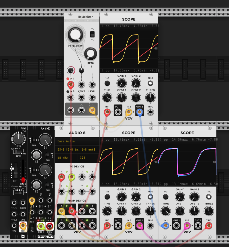
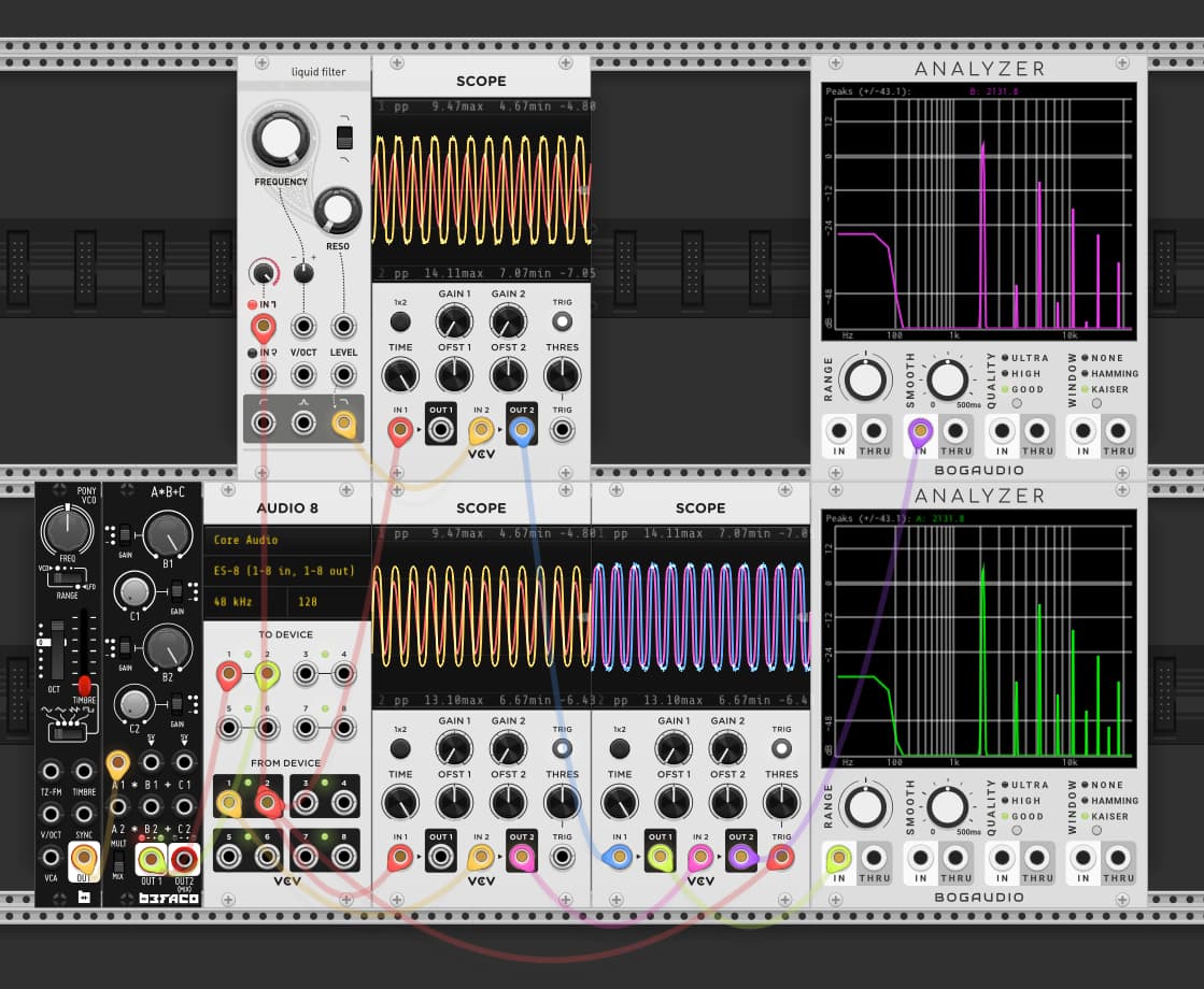
As a warmup, I can modify to output say BP4, by using the coefficients in Emilie’s pole mixing document.
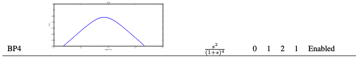
float bp4 = (lp2 + 2*lp3 + lp4) * kBP2Gain;
This works well, and I get good agreement with other BP4 models.
So far so good!
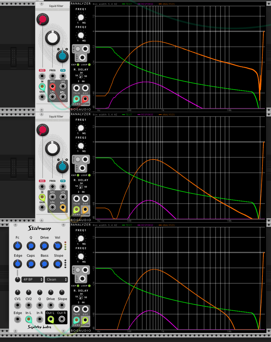
Highpass 2 pole
Highpass 2 pole
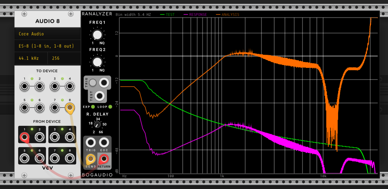
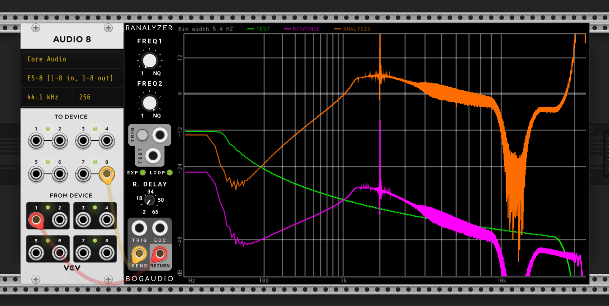
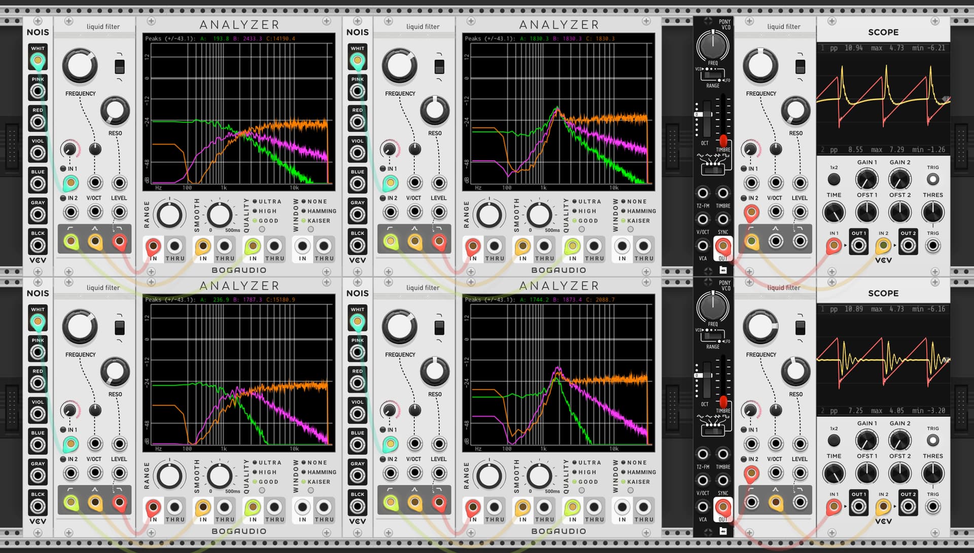
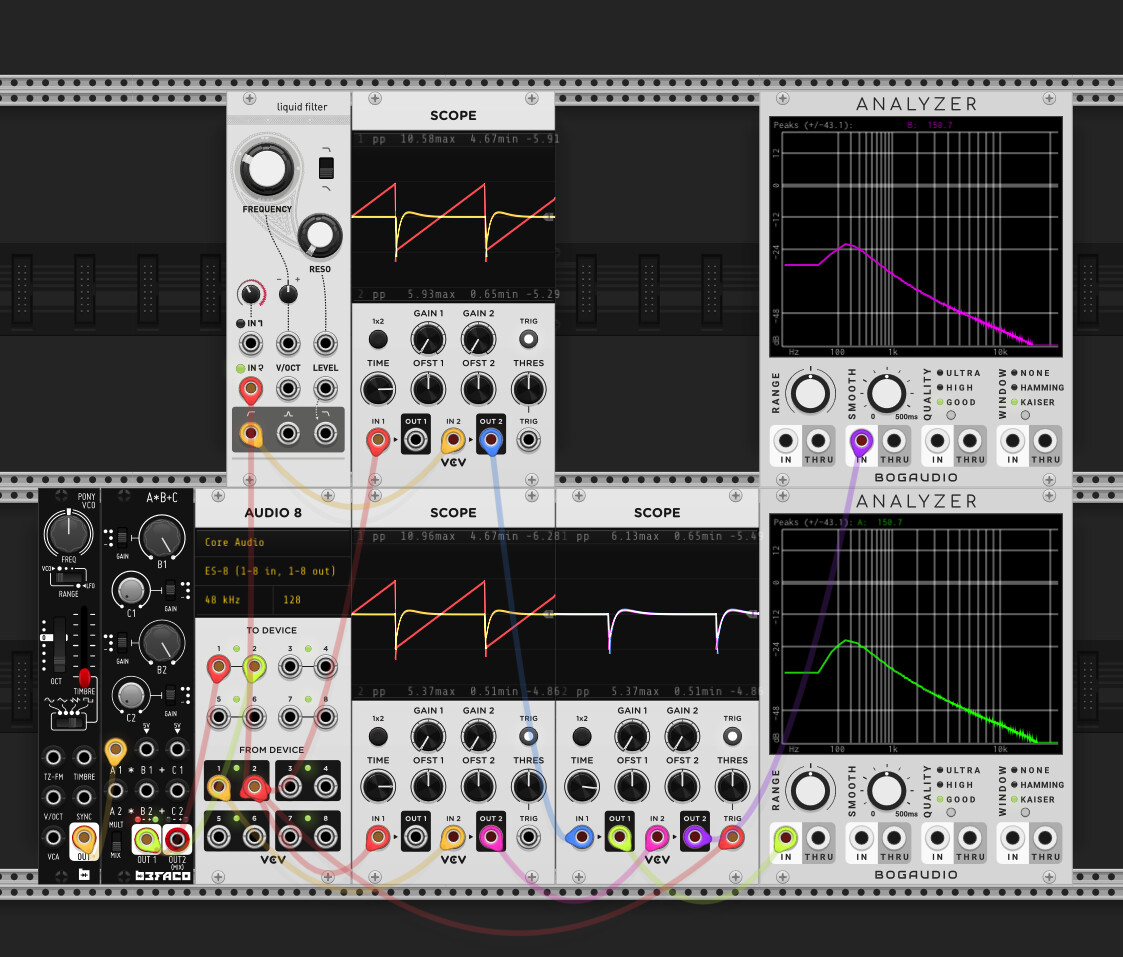
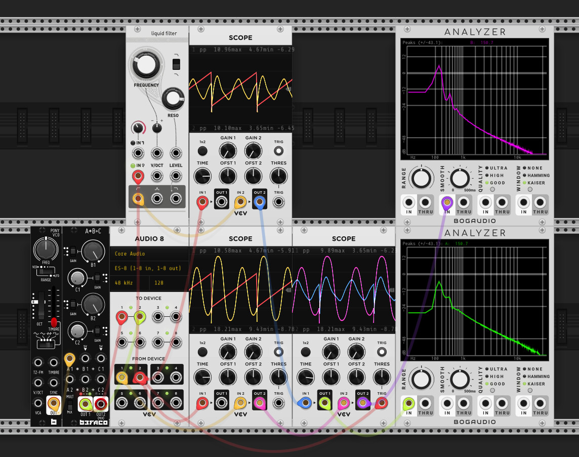
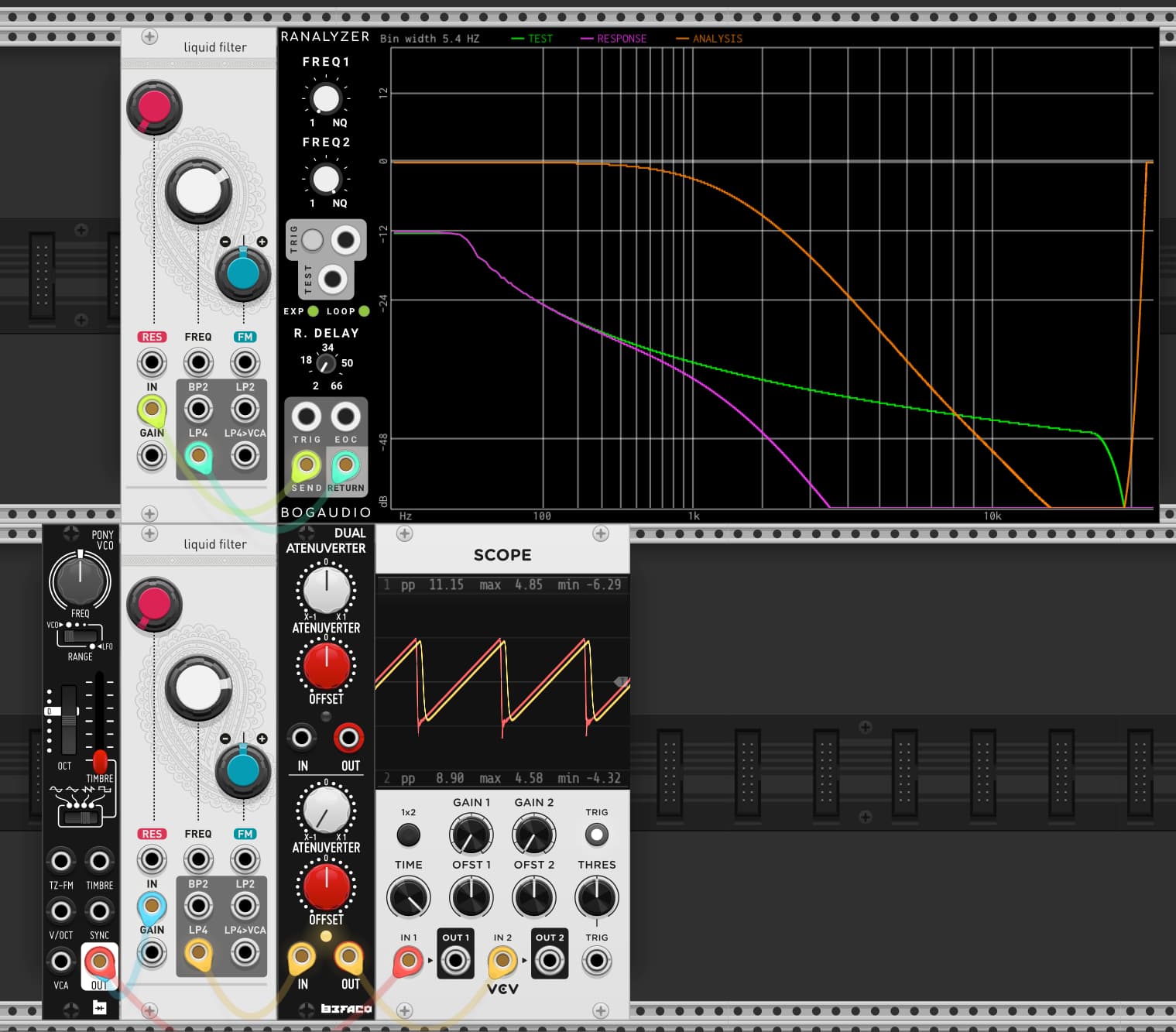
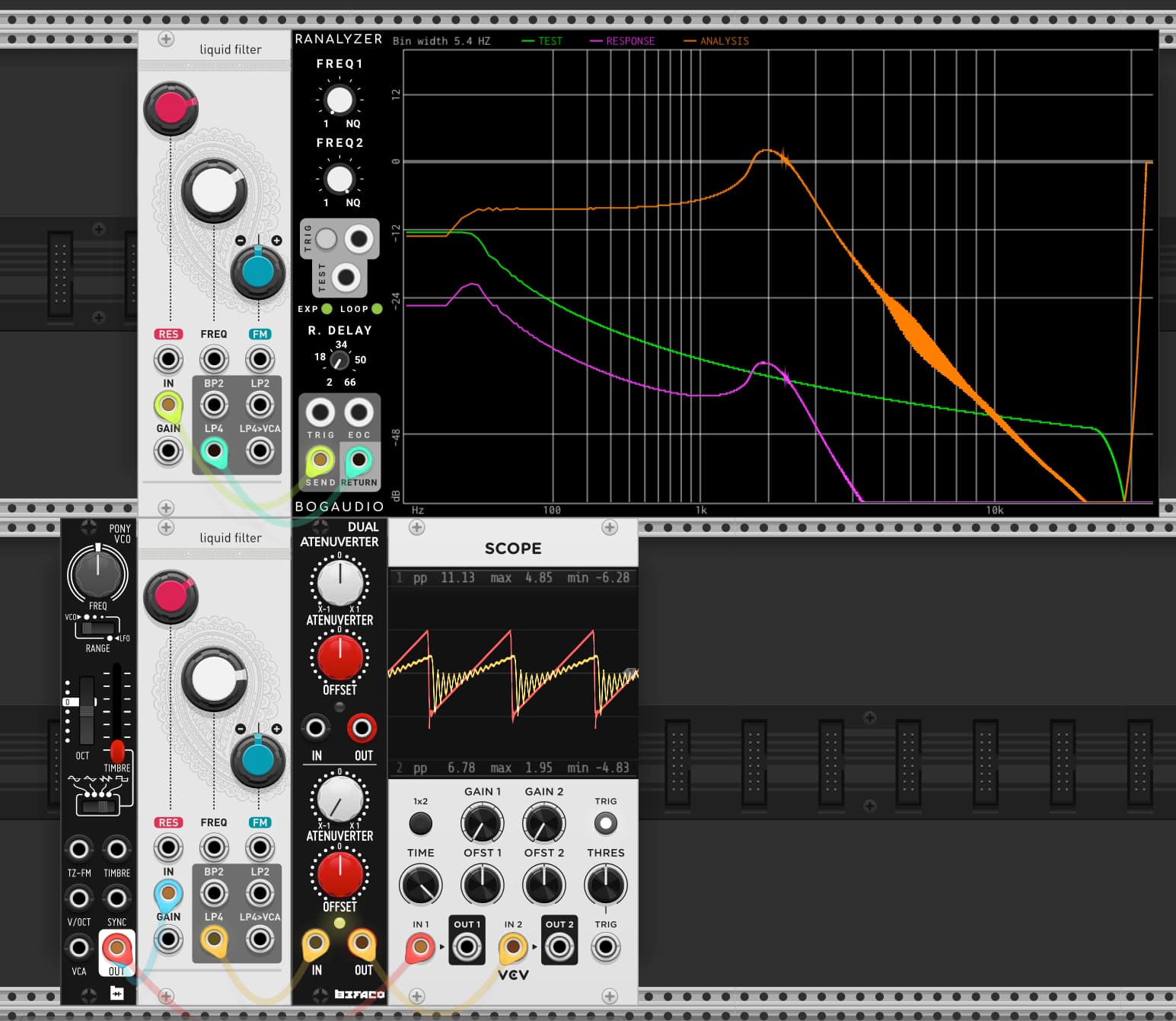
First I’ve taken a bunch of measurements of my Ripples v2 (ignore the notch at ~12k, that’s just ES8 doing something weird). It’s a little hard to tell, but whilst there isn’t a constant roll-off slope wrt resonance (this is documented in the manual), there is good attentuation at low frequencies.
| Description | Image |
|---|---|
| Resonance 0 | |
| Resonance 9 o’clock | |
| Resonance noon | |
| Resonance self osc onset (~2 oclock) |
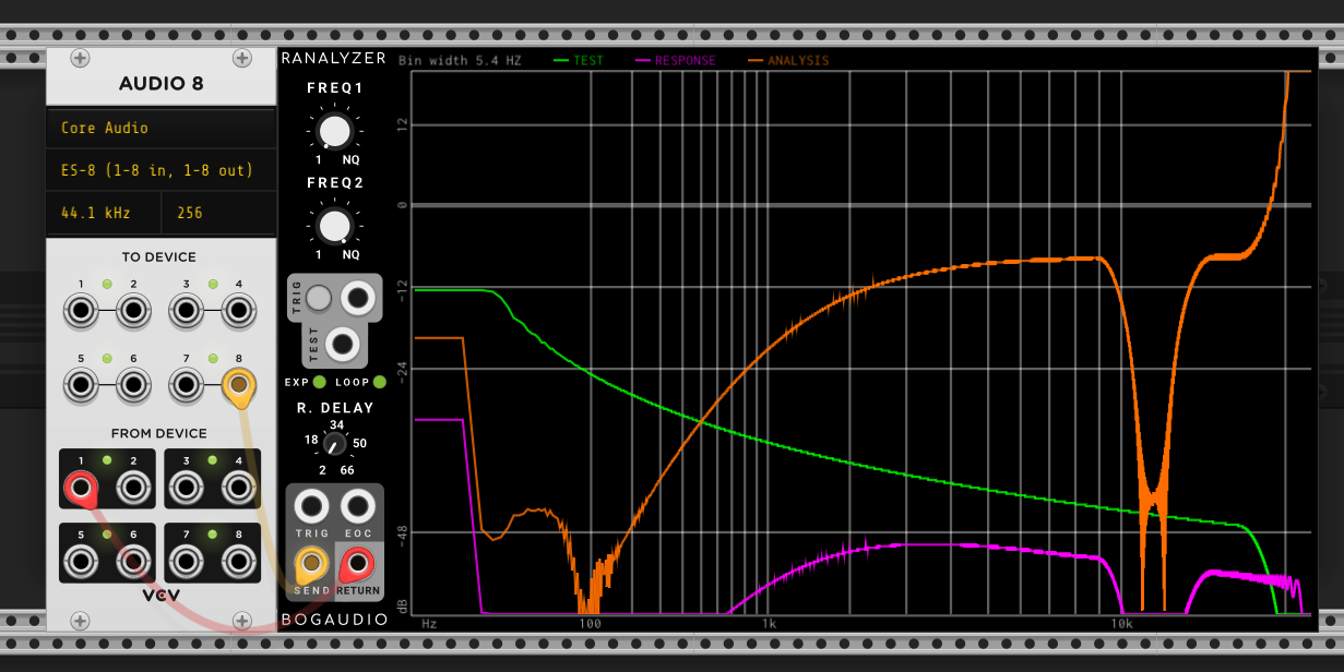
Approach 1:
According to electric druid page, you can get HP2 by the following formula:
Response name {Input, 1-pole, 2-pole, 3-pole, 4-pole}
12dB highpass {1, 2, 1, 0, 0}
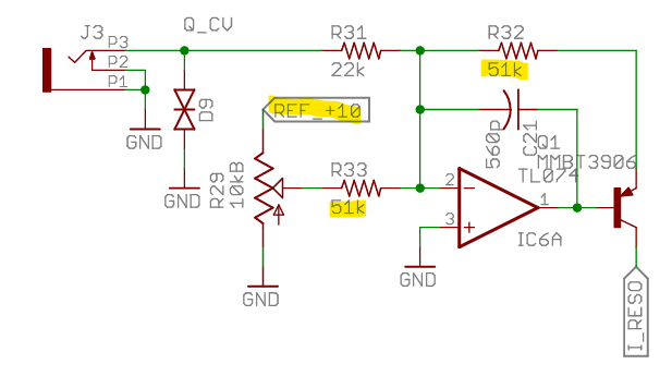
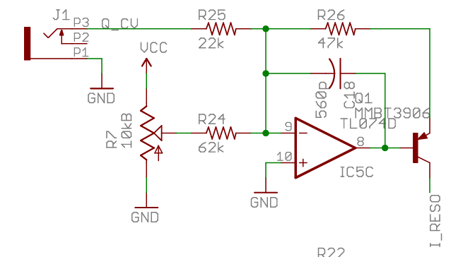
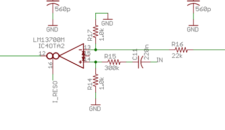
The Ripples v2 schematic actually shows something very similar
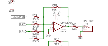
where (I think!) input is mixed with 2x LP1 cell + LP2 cell (here FILTER_IN is the attenutated input as it enters the 4 LP “cells”). I think the (inverting) mixer is combined with an active LP filter that doesn’t appear to be relevant based on cap and resistor sizes.
In code this looks like:
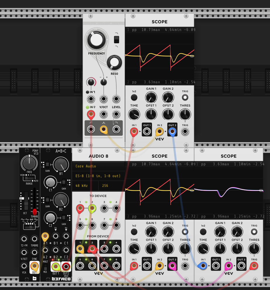
float hp2 = (inputs[0]*kFilterInputGain + 2*lp1 + lp2);
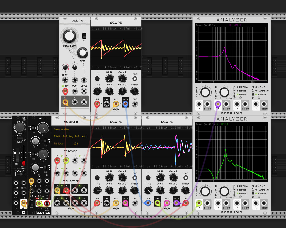
It produces something sensible at zero resonance, but looks less convincing at higher resosances. It does self-oscillate eventually though.
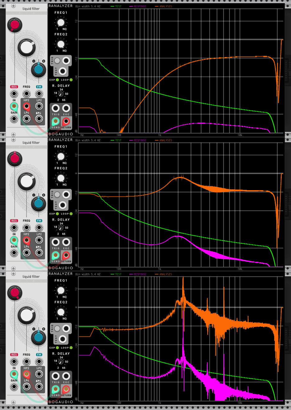
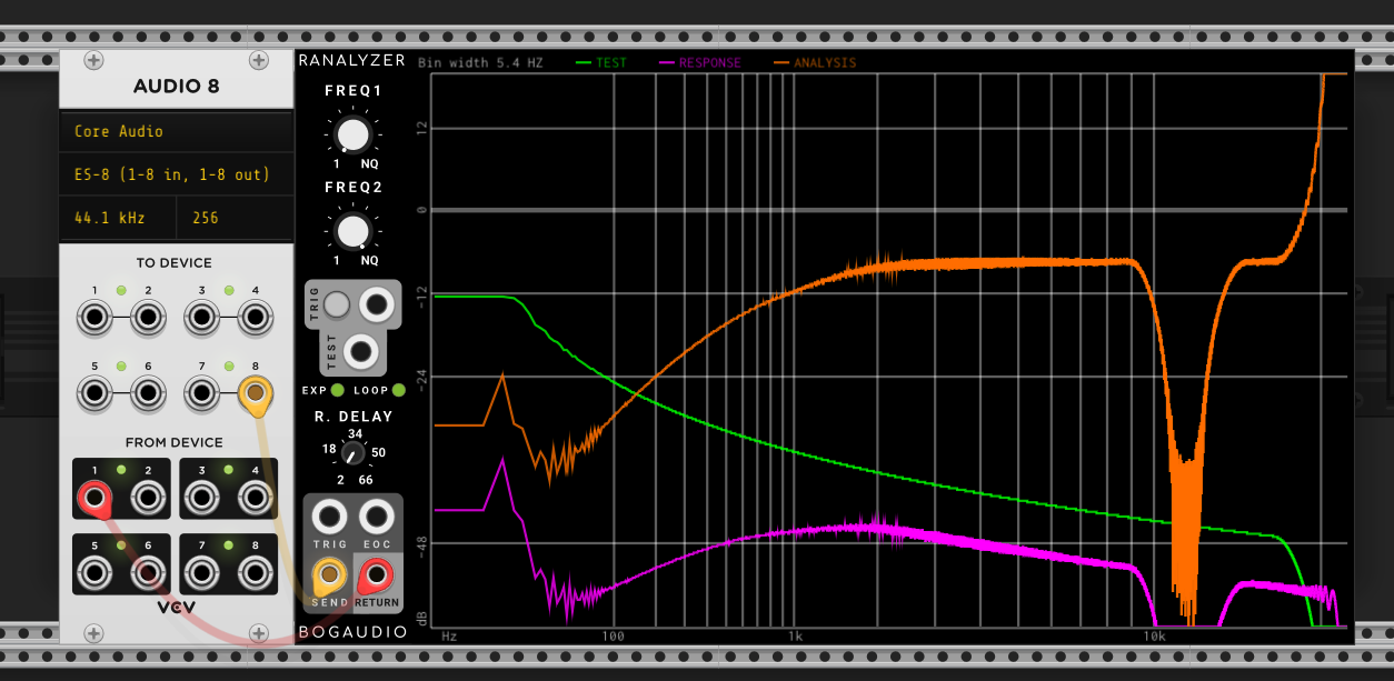
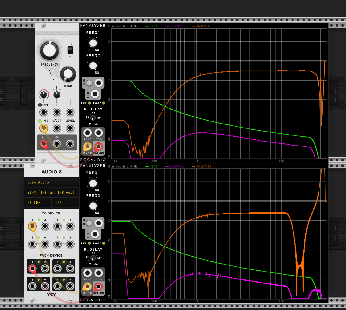
I am curious as to why this doesn’t work, given that the schematic shows something very similar. Specifically by “doesn’t work”, comparing measured and simulated with resonance at noon.
Approach 2 (not advised!)
Quoting the pinchettes pole mixing doc
A possible solution is to add a switch in the circuit to bypass the first low-pass cell (or more accurately use a lower integration cap to provide a very high cutoff-frequency). Using this approach, transfer functions of the form:
can also be implemented using the same circuit and the same design equations, with the only change that the first inverting 1-pole cell has been bypassed and replaced by a simple inverting cell.
I can manually set the first cell cap value to a very small value to approximate a short in the circuit, meaning the first cell is very close to a pure inverting cell. This is a bad idea though because solving dvout/dt = -A/(RC) * (vin + vout) with tiny C is a very stiff ODE, but as an experiment it is interesting as we at least can observe close to the behaviour expected (except no self-oscillation at lower frequencies < 5k).

Approach 3 (in progress!)
I next will try to explicitly replace the 1st LP cell with a pure inverter stage - my initial attempts to do this (i.e. inject -inputs[0] into the second cell) failed, so I might need to “un-roll/un-simd” the RK2 integrator to properly understand what is happening.
Conclusions/Questions
- It’s pretty straightforward to generate a subset of filter responses where all 4 LP cells are “enabled”, e.g. BP4
- Reponses where the First LP stage must be disabled are proving harder.
- I don’t know why an approach similar to the schematic (Approach 1) doesn’t exhibit the desired roll off behaviour
- Am I doing anything else stupid / missing an obvious solution to this?
I will continue and update this post but any help from those more knowledgable very welcome!
 Passband")

