I’m working on a patch that lets you control the drift of clocks based on a pendulum wave. I would love to add a visualizer based on JW’s Thing Thing. Is there a way to add other simple pendulums rather than adding angle to the same pendulum?
I’m thinking about trying to learn how to code one, but thought I would check the forum first to see if there is already something similar or if someone else was interested in trying to build something. Ideally, it could accept 16 signals to run 16 different simple pendulums and the length of each would be determined by an incoming frequency or clock signal. Any ideas or advice would be greatly appreciated!
Here’s the work in progress patch if anyone is interested!
isn’t a pendulum similar to a sine wave, or rather half a sine? so should be able to build it with some sine LFOs that have V/Oct or frequency input… Not tried, so just theorizing, hoping I understood what you are after…
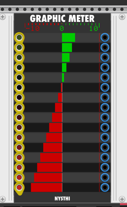
The closest I’ve gotten to the visual I am looking for so far is using the NYSTHI Graphic Meter to show LFOs synced to the clocks. There might be a way to do this with a 2D plotter, but I haven’t cracked it yet.
I got the 2D plotter hooked up. Using the clocks to control the x and y positions. It’s closer to the effect I am trying to get, but here the heights are arbitrarily set rather than being controlled by the clock speed.
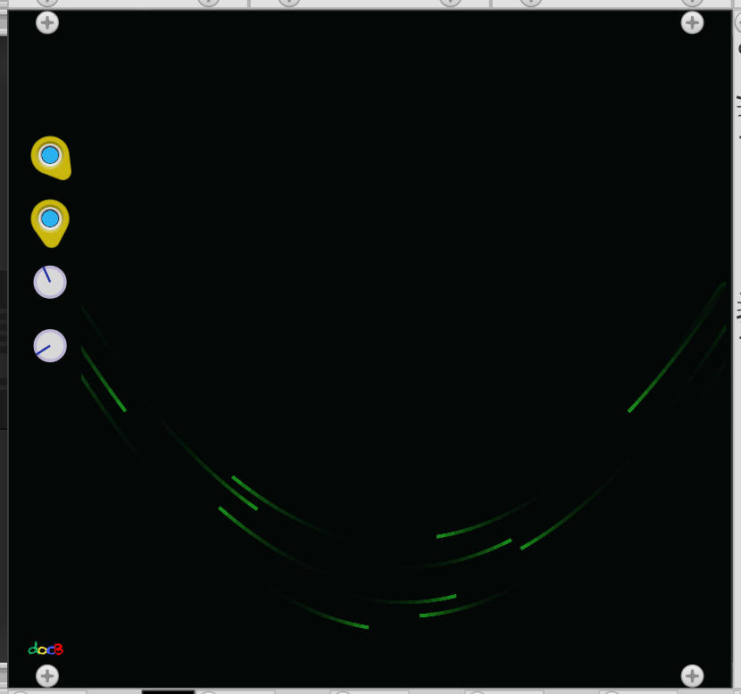
Using @fractalgee’s LFO idea, I worked up a patch that uses Bogaudio LVCOs’ FM input to adjust the spread between “pendulum” frequencies. The docB Plotter worked to visualize, but after running it for several minutes I noticed that the LVCOs never perfectly realigned. They were forming groups that were slightly ahead or behind each other. I’m not sure if it’s due to rounding or different numbers of cables adding 1ms delays, but the errors accumulate over time. Here’s a view of the effect after running almost half an hour. At this point, in a perfect patch, the LVCOs would be lined up.
Here’s a simplified version of the patch without the Plotter visualizer and with some added explanations in notes. Any ideas to achieve this customizable pendulum wave with more precision would be greatly appreciated!
Here’s a significantly streamlined version that takes care of all the math in docB’s Formula One (Thanks for the help, @DaveVenom!) All modules are docB or VCV Free modules with the exception of a Bogaudio LVCO that I couldn’t figure out how to replace.
I still can’t figure out why the “wave” is desyncing. Here are the leading theories from Dave who knows WAY more than I do about how VCV Rack works:
Limitations of single precision floating point
Inaccuracies in determination of 0 crossing, especially since the channels of the LVCO are running at different speeds, yet the tolerance factor is constant
If anyone has ideas about the source of the desyncing or possible solutions, I would love any help you can offer.