I’m just starting out with building modules for Rack, and I wanted share my early ideas for a module I’ve named imagine.
“pachde” is my brand, formed from the first two letters of my given, middle, and family names. Pronounced “patched” or “patch dee”, hence the logo: #d, because # looks to me like a patch on clothing.
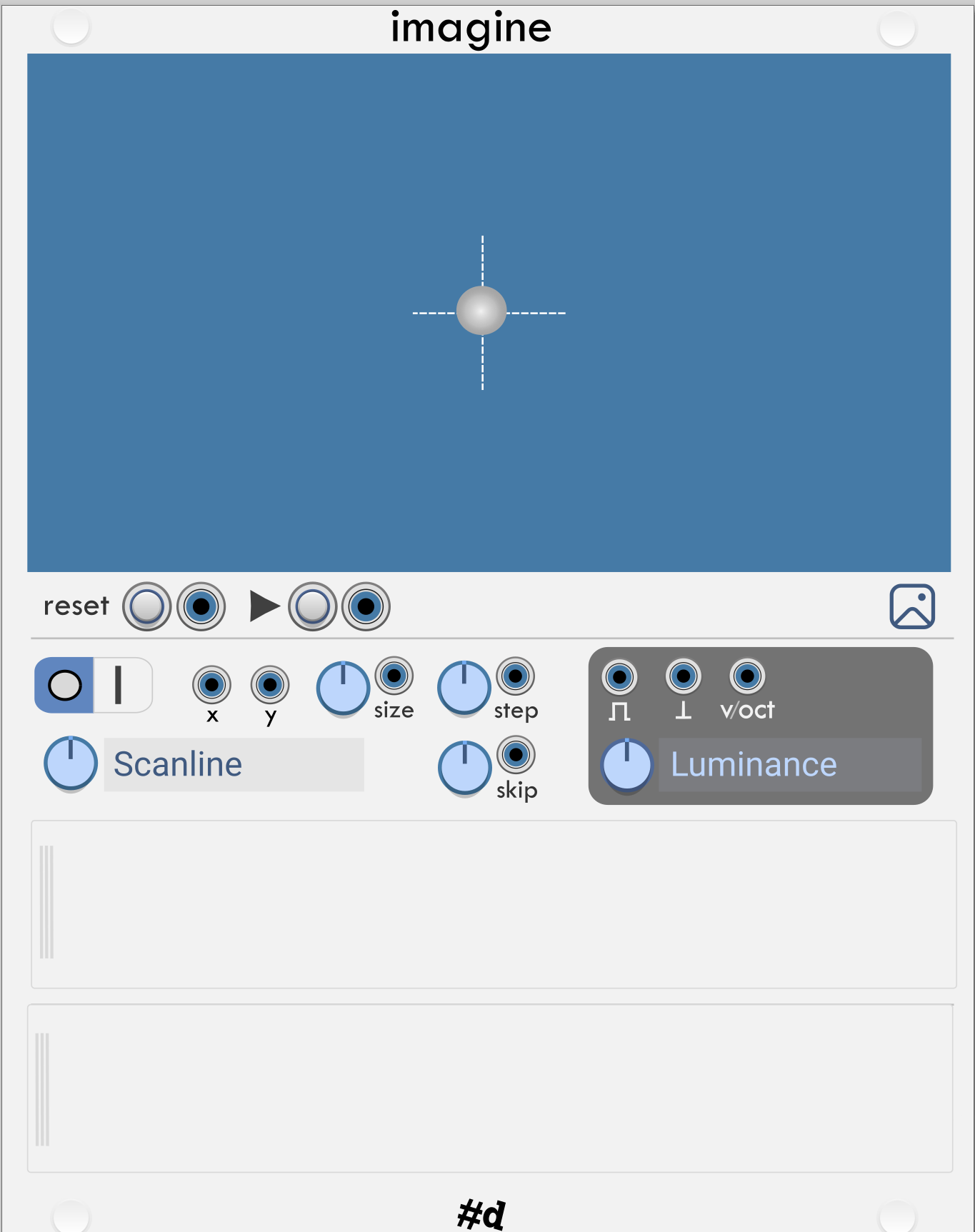
This module loads an image (you know, a png or jpg), and lets you set up one or more read heads. Each read head generates control signals – gate, trigger, and v/oct. I’m leaving direct audio generation to other modules. You can think of it as an eccentric sequencer, rather than an oscillator.
The circle with crosshairs suggests the read head. (graphic here likely to change – I need to think about how to set initial position.
There is room for this set of inputs and outputs to show 3 read heads.
Buttons+inputs for Reset (go back to starting position) and Play/Pause.
Click the “mountain and moon” icon to Open an image file.
Then, three rows for read heads. Number may vary in final module. Additional read heads may be possible with a future extension module. (Possibly a premium plugin, if I decide to go that route).
To keep the UI uncluttered, this prototype hides unused read heads behind panels. Double click the “gripper” to remove the read head cover. Read heads with cables, and the first read head can’t be covered. Might be too cute an idea and more than needed for MVP.
I’ve read the debates about screws vs no screws. I lean to no screws to reduce the visual noise, but I understand people want it to look like something physical like you might see in a EuroRack, so I’ve taken a middle position and put nice caps on my screws. I might even make it possible to remove the caps and show the screws in all their slotted glory for the die-hards who like screws. Binary menu options are simple.
Read heads
Read head shape: circle or bar. Circle samples the image for a given radius around the read head position. The bar reads a small vertical rectangle of the image.
Inputs for x/y position of the read head. Protocol TBD, maybe 0-10V or 0-1V for position in proportion to image dimension, maybe selectable in right click menu.
Knob+input for read head Size. Knob is attenuation when a cable is connected, otherwise absolute size.
Knob+input for read head Step (or Speed). Signal protocol TBD.
Knob+input for read head Skip. This produces a gap or spread when the read head reaches a boundary.
Knob for Path (or “orbit”). This selects from a number of ways a read head could traverse an image. When you have cables on the x/y inputs, Step, Skip, and Path are ignored. Possible selections: Scanlines (left to right, top to bottom), Other scanning-type paths: RLBT, LRBT, TBLR, BTRL,…), Boustrephon (alternating left to right then right to left scanning down, Circular, Album (spiral in, like a vinyl record). Pong (randomized bouncing at the edges), etc. Might need some controls to set a trajectory for some paths, like starting point and angle, then a toroidal (wrapping) at image edges. I can start simple then figure out the UI for other ways of getting around.
Output:
Straightforward Gate, Step, and V/Oct output jacks.
Knob to select data used to generate the signal. Possible values include any of the fundamental components of a pixel in various coding schemes: Luminance, Lightness (from HSL), Value (from HSV), Hue, Saturation, RGB Ave, etc. Gate and trigger happen when a value crosses a threshold looking at previous and next samples of the image. More sophisticated edge detection may be required or useful. Might need a knob for threshold/sensitivity.
Example use case
Imagine your image is rows of bar codes defining rhythm patterns. For this use case you want the bar read head shape, a size matching the height of the bar code, a skip for the gap between rows, and the Scanline path. V/Oct output is unused.
The output knob will let you choose the value going to the V/Oct. With 3 read heads you can have them all on the same path and choose the H, S, V (or L*ab, HSL, RGB, Luv…) component for the 3 outputs. it might be useful to provide a switch for a normalled inputs – where 1 read head feeds all 3 outputs.
There are too many possible components to provide outputs for them all on the module surface, unless I provide only a single read head.
I didn’t see a doc link for Sparkette’s module, so I don’t know the ranges it expects for the inputs. 0-10v? Are there other modules that want color components for input?
Might do a square read head, too. Particularly useful when you’re manually designing an image for precise control, and using a small size 1-8 pixels averaged.
The circular makes more sense for large images (like landscape photos), and as suggested by the circle’s gradient. I’m imagining circular gaussian-weighted sample centered at the x/y pos with a radius given by the size knob/input.
I haven’t written any of the sampling yet, so it’s hard to predict what sampling technique will give the most useful results. Much will depend on the size and nature of the input image, so I want to provide option, with a reasonably clean UI.
This looks like it’ll be a nice tool. Thanks Paul. What do you think of getting it to load animated .png or .gif files? The only module I know that can load an animated gif is computerscare’s, but it’s purely a visual panel. VCV Library - computerscare Custom Blank
@cosmoproductions – Good idea! Animated formats could be supported. I can image a number of ways to use them, either advancing the frame when the current frame has been fully traversed, or by scanning all frames before advancing the position. I can add this to the backlog – I want to get to MVP first to see if I can get musically useful information from images using simple methods.
@existentia - Thanks for the reference to Loco TEX – from the description it appears to be a very simple version of the idea here. I looked in the Rack library and didn’t find it.
At the moment I’m focusing on control information via relatively naive methods before advancing to audio-rate spectral processing. That’s higher-level DSP+math that I’ll need some time to digest ;-).
I’m interested in hearing about what types of signals would be most useful on both inputs and outputs: Unipolar 0-10V, bipolar -5-5, 0-1V? CIEE color standards are usually 0-1.0 floating point values, but easily converted to any of these voltage ranges.
Finally, haha. I think I even wrote about this kind of idea in my “wet dreams” thread, haha (aka ideas for any interested developers) or somewhere else. I don’t even remember now.
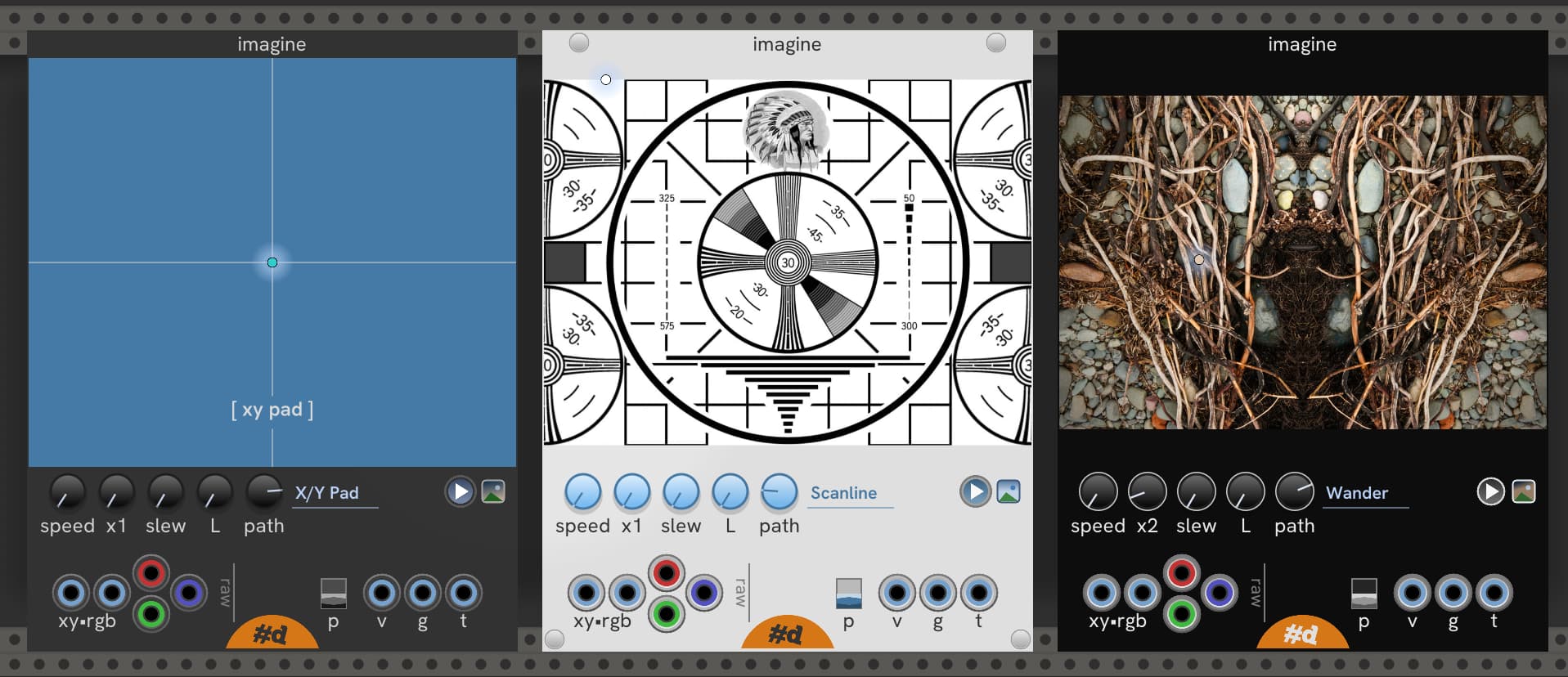
Here’s a snapshot of the current implementation so far. I think I’m very close to beta-ready.
What you see is three copies showing the Dark, Light, and HighContrast themes. Two instances have loaded images, and the third without an image has the Path set to XY Pad, and the module acts as an x/y pad. All knobs are clicky == increment (decrement with CTRL/CMD click).
Turns out there’s only room for one read head. Additional read heads would have to be by extension modules.
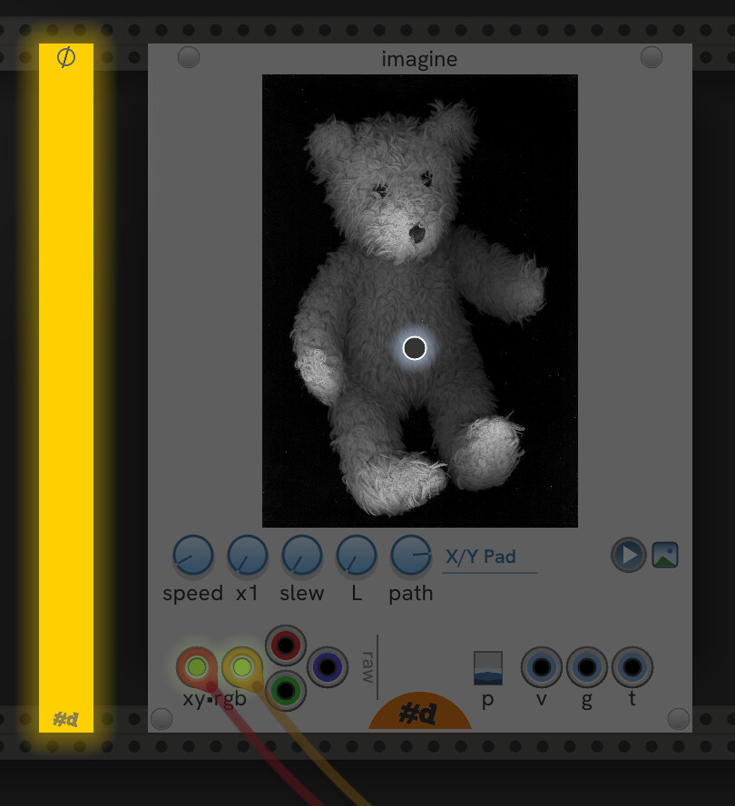
The read head is animated and lights up when the room is dark.
Not shown: the Null (blank panel) and Info (notes module). Null is done, and Info is MVP (setting text is via plain text menu entry – no editing, but this is all some other notes modules do).
TODO:
implement gates and triggers. Will probably needs UI to set thresholds, and I have a rough design for that widget.
I’m tempted to add in input port to animate the brightness of the light, but that would clutter the panel. Maybe turn one of the screws into an input port ;-).
Maybe better to hold off and get gates and triggers for imagine working, but this is what happens with fun-down development.
Is the source image in Imagine visible with Room Brightness turned down? I can’t tell from this example. How about a right click menu option to enable/disable the image’s visibility when room brightness is down? Perhaps vertically aligning the top and bottom screws would be more consistent with the visual style in VCV. Thanks for your work on this. Looking forward to trying it out.