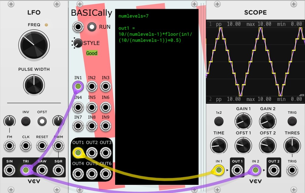
I would like to quantize CV values to a pre-defined but variable (selectable) number of levels, for example 7 levels including the bottom (min) and the top (max), plus the 5 levels in between.
So, I managed to come up with a suitable formula in BASICally involving the floor function (see pic), but am wondering: Is there already a module that can quantize CVs to a predefined number of evenly distributed steps?
I know there is ‘Steps’ by cf, but changing the number of steps there also changes the signal range.
Thanks for trying BASICally! Your solution seems to have trouble with even values of numlevels, as you likely noticed.
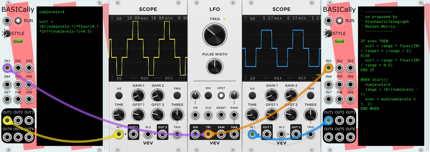
After a lot of fiddling, as weird looking as this is, I think this BASICally code might work closer to what you want:
IF even THEN
  out1 = range * floor(IN1 / range) + (range / 2)
ELSE
  out1 = range * floor(IN1 / range + 0.5)
END IF

WHEN start()
  numlevels=7
  range = 10/(numlevels - 1)
  even = mod(numlevels + 1, 2)
END WHEN
doesn’t a good quantizer need some hysteresis? It never seems right to me when an “in between” input can make the output swing wildly between adjacent quantized values.
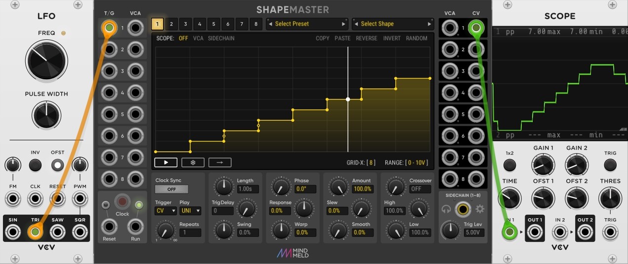
Thank you for this great recommendation, steve! Shapemaster is splendid, although I know I still need to get to know it a lot better.
A strong point is that I can draw in any quantization shape I like. The number of steps on the x-axis can be chosen with ‘Grid X’.
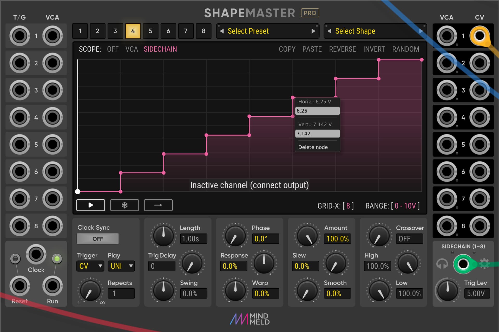
However, how do I adjust the ‘Range’ grid on the y-axis, as it seems to be fixed with the ‘Range’ parameter (0-10 V in the pic)? I am trying to have 8 steps cover the range of 0-10 V evenly, so I am assuming this would be easier to draw with an 8 step y-grid.
Thank you so much for looking into that and for your response! I really like BASICally, even though my coding skills are rather rudimentary. It makes me dig up some long-forgotten learnings .
Actually thought that my formula provided me with what I had in mind, including coverage of even numbers (see pic with the example numlevels=4).
Nevertheless, I don’t know whether what I envision might still be less practical than the code you are proposing. Your code stratifies between even and odd numbers for ‘numlevels’. Can you help me understand why this distinction is needed or beneficial? It also seems that your code reduces the signal range on the y-axis and, using the example of numlevels=4, only yields 3 steps.
[Independent of all that, I did simplify my formula a bit more in the meantime, so the streamlined form I currently use is:
Hi Squinky, I may not be advanced enough to fully appreciate that. How would the respective curve look like? Isn’t quantizing all about the jumps and to avoid soft transitions, e.g. when thinking ‘pitch’?
You can’t change the Y grid - it changes automatically based in the range selected. For 0-10V the grid is 10 x 1V steps. What you have done in your grab, using 7 of the 10 steps, looks fine - there’s no need for it to go all the way to the top.
Not sure I completely follow Bruce - what do you mean by an “in-between input” - can you give an example?. In ShapeMaster any voltage down to a few decimal paces can be mapped to any other voltage you want. And because the mapping is constant across the range, there are no ‘in-between’ values as such - any given input will be mapped to a given output. The only way you would get the output swinging between adjacent quantised values would be if your input signal had some 'vibrato-like" modulation that happened to be centred around the change point. By that I mean if the change point was set to 1V, and the input was modulating between 0.97 and 1.03V, you would get the swing between adjacent quantised values - but if the input is constant, there’s no swing.
Also, if I understand correctly what you mean by hysteresis in this scenario (a ‘range’ around the expected change point?), I think you can just draw that in. By that I mean if you expect a change to happen at say 1V, but you want to give a little room for error around that, you can make it happen at 0.9V or 0.9675V instead for example - or whatever other value you want.
Perhaps I have misunderstood you though.
I’m not claiming ShapeMaster is the perfect quantiser by any means, but it’s kinda unique in that it lets you design your own quantisations and it’s easy to do things like give additional probability or ‘weight’ to certain notes in a scale (when fed with a random input) which is not so easy to do with a traditional quantiser.
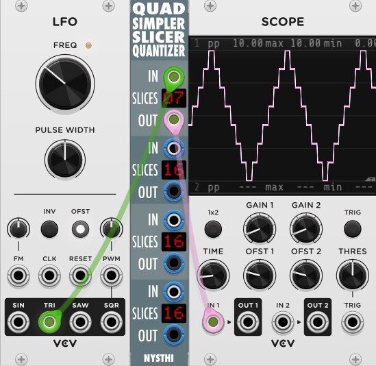
To stretch out Shapemaster’s 0-7 V output of the example into a 0-10 V range with 8 levels (7 slices), I would simply scale the signal with an additional module, such as Bogaudio’s Offset with an amplification factor of 10/7.
Sure. Say you are quantizing to the regular 12 tone even tempered scale. If your input is right in between C and C#, do you output C or C#? With no hysteresis an infinitesimally smally change in input would cause you to switch back and forth between the two. Often that isn’t what you want. That’s why, for example, the VCV spec for gates also has hysteresis. Because you won’t want any noise or ringing on the gate input to trigger a burst of events.
This could easily happen is you are quantizing some sort of noise or noise-like random source.
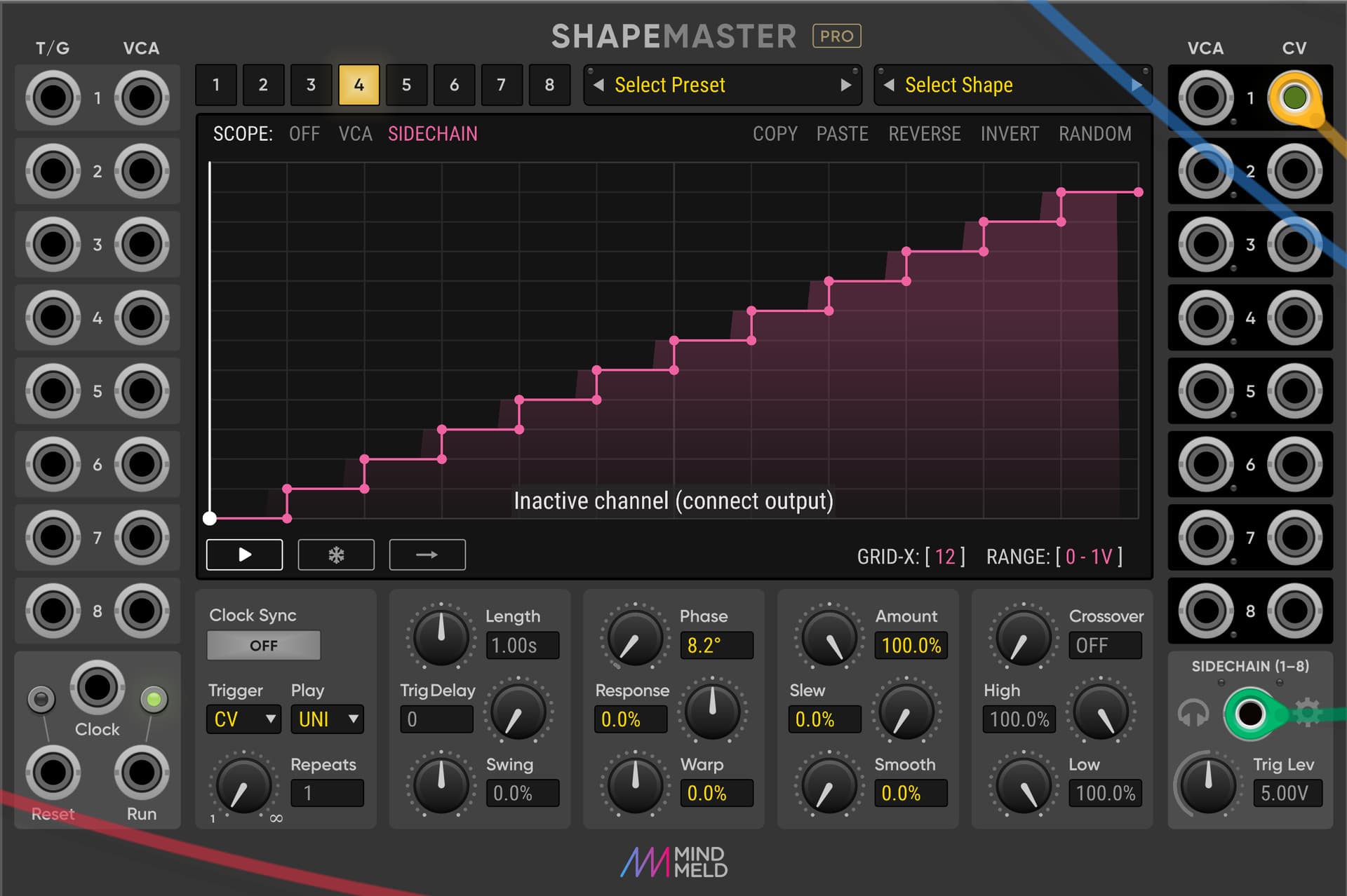
Oh I see - sorry I misunderstood you originally - I thought you wanted to convert a 0-10 input into a 0-7 output - but what you want is both input and output to be 0-10V but with 8 levels (7 slices) right? In which case yes, I could see how having a Y grid value could help with that, but it’s still quite easy to do as you can input specific X and Y voltage values for nodes by right clicking on the node.
So you just make each vertical step 10/7 = 1.42857… SM gives 3 decimal places so your steps would be: 0, 1.429, 2.857, 4.285. 5.714, 7.142, 8.571, 10.
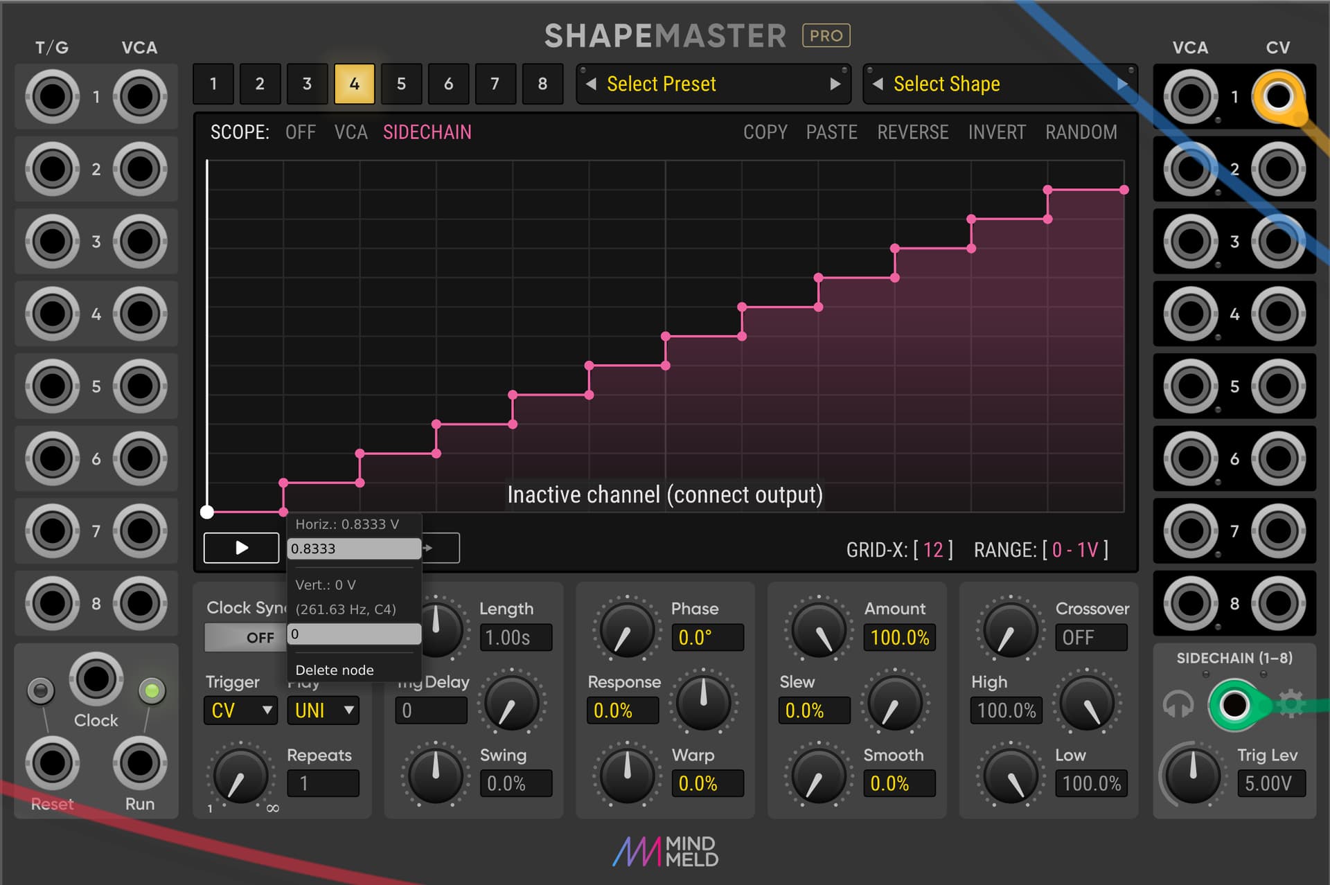
Well with SM as I said the quantising is constant - for every input value you can set a corresponding output value. So a really basic setup could look like this where everything below 0.8333V (C#4) is treated as C4, and everything equal to or above 0.8333 is treated as C# (until you hit D)
yes, but no hysteresis. Well, that’s fine, I’m sure plenty of quantizers don’t have that.
[ in case the distinction isn’t clear, with hysteresis the transition for c to c# would occur at a higher voltage than the transition for c# to c. Thus avoiding switching back and forth between the two if the input is right in between and has a little noise on it, too. ]
Right - no hysteresis - it’s just remapping one voltage to another So missing a feature that some quantisers have, but also offering features that other quantisers don’t (designing your own scales and weighting of notes in the scale, or across octaves as mentioned earlier)
I’m speaking mostly out of ignorance here, but scientists prefer to use the “ansatz” term which means an educated guess starting assumption (in contrast to a “SWAG”)…
When I was coding a quantizer for Meander, I looked a lot of quantizer modules’ code. I do not remember seeing the term hysteresis in any code, but there were a lot of variations of approaches, some of which were not really clear what and why they were doing what they did.
In the end, I followed the example of the VCV brand quantizer QNT. I used the approach but recoded the algorithm. The interesting thing in it for me was that it does a bidirectional search for the nearest note, rather than giving the user a choice between two or more search scheme, such as “closest up” and “closest down”, etc. I partly used this scheme as it reminded me of a binary space partition algorithm as I have used many times over the years in various sorting, sampling and even 3D game engine rendering. In 3D, there is an effect called “Z buffer fighting”, where pixels on the screen start “arguing” as to whether the 3D projected point in the scene that corresponds to a 2D screen pixel is closer or farther away from the “camera” so distance occlusion will work properly. In those game engine days, I spent a lot of time trying to keep those pixels from fighting and flickering