I’m trying to build a Seq, and I’m facing a huge problem on sync the desidered sequence with external modulation. This because Rack is always 1-sample delay for each cable between modules.
In my case, I’ve:
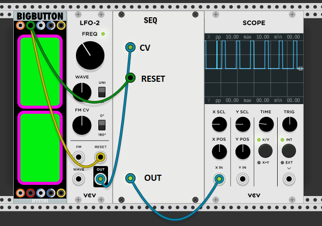
Trig → Reset Seq
→ Reset Mod
Mod → CV Seq
Somethings like this:
Once I trigger (sample index 0), I reset both Seq and Mod the next sample (sample index 1), and the Mod send the resetted CV value to Seq another sample ahead (sample index 2)
When the Seq reset (sample index 1), I don’t have the real/actual value of the resetted Mod value, because it will come in the “future” (i.e. at the next sample).
The fact is: in the Seq reset stage, I decide (for example) if start or not a trigger for that first step, based on the CV value of mod.
So it happens that “sometimes” it play, sometimes doesn’t, depending by the value of the last Mod value before reset, not the actually first reset value. That’s because when I evalutate the CV, it always get a “random” value, due to when I click reset, not the first (fixed) mod value.
I could simply “discard the first sample on seq reset, and take the next from CV”, which allows me to get the real resetted CV mod value. But what if I place another cable between the Mod mudule and the Seq CV? The delay will be 2, so I should discard 2 samples and take the next. And so on, whatever number of cables I will place. I can’t mange this.
Is that a “limit” on VCV Rack? Which will always introduce inconsistency?
Or do you know a way to resolve this?
If I “ignore CLOCK triggers up to 1ms” I will receive a different CV value once “I read it after 1ms”, depending of the amount of cables between Mod and CV.
Because the actual value is shifted by the number of cables. So the 44° CV value I process ( 1ms at 44100) is different if the Mod have 1 or 2 cables between it and the actual CV on Seq… right?
Its under construction. All the settings are hardcoded right now; later I’ll add what I need.
The CV pilot how to trigger step based on the input value.
That’s irrelevant I guess.
The clock is managed by the module itself (its 60bpm now.
The problem is on “reset”, where I reset the sequence…
You will get more params in the future, don’t worry
As I said, based on that CV value, I evaluate how to trigger each step.
Once the Seq need to trigger a step (I have 16 steps in 1 beat length pattern at 60bpm), I read the CV value and evaluate if trigger it or not.
Well, that’s the key. I assume your “CV” input produces some sort of clock at time t to advance your sequencer’s state. The standard says that if your module resets between t - 1ms and t, the clock should be ignored.
My sequencer advance your own way, following its bpm counter and division.
Don’t need any external clock here, its internal.
CV is NOT clock, is a CV signal from any modulator (LFO-2, for example).
The problem is “which sample” (i.e. the CV value) is read, when I need to read it.
This reading is single (i.e. a sample), and due to it some settings are evalutated accordingly (in this case, if the step play or not, when internal clock occurs).
But if this CV value change due to the number of cables between the modulator and the target CV, it becomes inconsistent…
Oh, I assumed that your clock had a dependence on the CV input, because you directly said it here.
I still don’t understand why the timing standard doesn’t apply. If your module is generating clocks internally, you should ignore your internal clock up to 1ms after a CLOCK trigger is received. If your CV input is only read upon an internal clock, then it won’t be read shortly after receiving a RESET trigger.
I think you don’t get what CV input value does for steps Probably because english is not my native language, sorry. I try to re-iterate.
CV “evaluate how to trigger each step” means that based on the value, when the clock “tick”, it determine if start a trigger (on out) or not.
Very basic example: I setup a seeded sequence of random values, for each step (so, if I have 16 steps, 16 random values). Fixed, when I load the plugin.
Once a step need to start (i.e. clock “tick”) I read the input CV value, and if the value its >= of the seeded value for that step, I do a trigger out. Else, it doesn’t trigger. And so on for each step.
Thus:
if for step n. 2 I have a seeded prob of 0.3 and I read from CV 0.9 (1 cable delay) the step will trigger; but if I add another cable between Mod and CV (which introduce a sample delay), it will read another CV (that could be 0.1), and won’t trigger.
When doing logic with gates, you need to “clock” your gate evaluations, just like a microprocessor. If you build a black box in analog/digital hardware or VCV Rack with N gate/CV inputs and change one of them, you need to wait some time for the “dust to settle”, or in other words, for the gates to stabilize. The “clock rate” is determined by a reasonable minimum amount of time it takes your gates to stabilize, and for Rack, 1ms is typical. If logic in circuits was instantaeous, CPUs could have unbounded clock rates. Instead, they clock at rates on the order of 1GHz for the fastest processors.
What this means for your module, I don’t know. But that’s up to you.
What does it means “for the gates to stabilize”?
CV, by definition, is varying during the time. Its a modular system, I’d like to provide CV signal.
Even if I sample (& hold it) the CV input (this is what you mean with stabilize?) it will vary due to the number of delayed sample. So clearly that’s not a solution…
Are you saying that I can always do this supplying DC values to my Param?
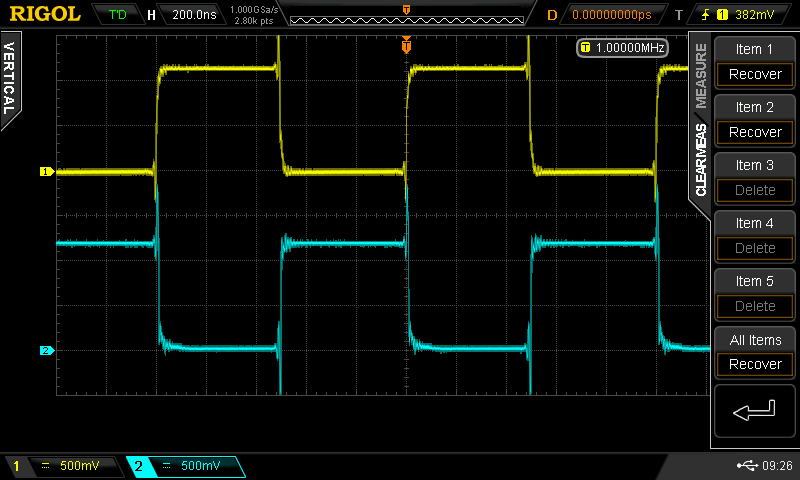
If you’re ever messed with logic circuits, you’ll notice that transistors, logic ICs, etc have a nonzero response time to a change of input.
Of course in Rack, there’s no slew like in the picture, but there’s 1-sample delay in cables which gives a similar result.
In hardware, you’d need to wait some time between changing gate inputs and reading the output. In the context of your module, you could delay 1ms or so after your internal clock before reading CV inputs. There are many other ways to solve this issue.
No This won’t solve the problem. It only delay the read of 1 ms.
Let say I delay the reading of CV input of 10 samples (instead of 1 ms, so I can show you what I mean), as you suggest.
Mod output from 0 to 10, with a sine walk (0 to 10 to 0 to 10 and so on).
1 cable between Mod and CV.
Seq will receive:
0 0 1 2 3 4 5 6 7 8 9 10 9 8 7 6 5…
Let say I reset, and as said, I read the value after 10 samples (instead of 1ms). So it reads the value 8.
Now add a cable between Mod and CV (2 cables), that basically do nothing (it just pass the signal as it is).
Seq will now receive:
0 0 0 1 2 3 4 5 6 7 8 9 10 9 8 7 6 5…
Now I reset again, and if I read the value after 10 samples (instead of 1ms), it reads the value 7.
Which is different!
That’s the inconsistency I refer to.
I think your problem is that you are running your example at samplerate, e.g. 48kHz. Your description may be technically accurate, but isn‘t it irrelevant because your sequencer won‘t be running at samplerate? Which input will provide such a sequence with 48kHz?
As @Vortico said, wait some time before holding the next sample from the input. You have to assume that the input changes not that much within a short period like 1ms.