I was thinking of the case where the modulator and isn’t a sin. Maybe that’s not an option on this one.
Something I forgot about, that’s worth keeping in mind when doing any kind of precise measurements on Neóni (or any other Instruo module):
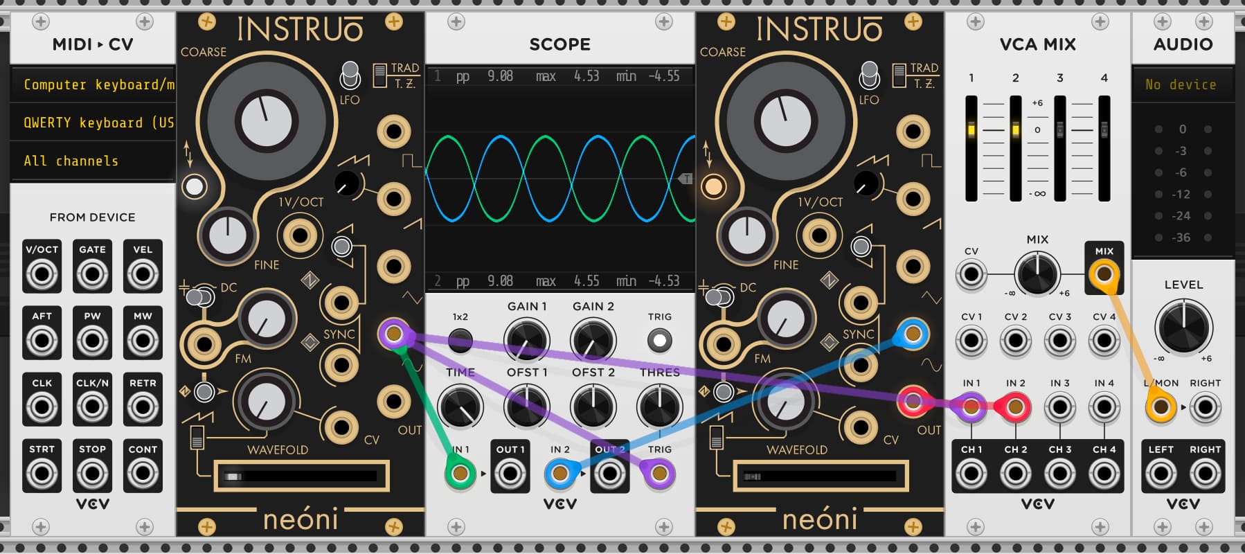
Each module instance is unique unless you duplicate the module. The analog-modelling variations are stored in the module preset, for example this what it looks like for Neóni :
"deviations": {
      "frequency": {
        "minimum": 4.9221057891845703,
        "maximum": 36986.58984375,
        "fine": 294.71685791015625,
        "vpo_error": 0.0025462107732892036,
        "fm_bias": 0.10182031989097595
      },
      "amplitudes": [
        4.6731810569763184,
        4.9873456954956055,
        4.8539471626281738,
        4.6713700294494629,
        7.5132479667663574
      ],
      "wavefolder": {
        "minimum": 0.62925446033477783,
        "maximum": 0.8389657735824585
      },
      "waves": {
        "sawtooth": {
          "bias": 1.0427894592285156,
          "invert_level": -0.19707153737545013
        },
        "sine_shape": 1.8943305015563965
      }
    }
Here’s a patch with 40 Neóni modules where I made sure to never duplicate a module, so each one is unique. All 8 groups of 5 are configured the same (in fact the parameters are tied together by instances of stoermelder MIRROR) and running through the same algorithm sequence (via Algoseq’s polyphony in this case), yet the result is obviously not the same. I cycle through the 8 via MixMaster, and each is plotted on the analyzer. I think the result is very interesting. Really an Instruo-specific sort of chorusing effect. ![]() Just scratching the surface. It would be cool to see these variations across polyphony channels of a single Instruo module.
Just scratching the surface. It would be cool to see these variations across polyphony channels of a single Instruo module.
(with apologies to Thomas Dolby)

neon sisters algmp.vcv (16.0 KB)
5 Likes
Very interesting find, and cool patch.
I’m pretty sure I either read, or saw demonstrated, this technique of introducing slight random variability for each instance of a module that emulates analog hardware. But I had completely forgotten about it. I don’t remember which plugin used it.
I need to test to see if I see variability in the coefficients that I measured. At this point I’d almost be shocked if I don’t see variability.
2 Likes
It’s disturbingly pleasing to know that this little experiment would cost ca. 15000 EUR in Eurorack world.
4 Likes
Hmmmm - I found the wave inversion parameter “invert_level” in the preset - and it appears to be restricted to the sawtooth wave!
  "waves": {
    "sawtooth": {
      "bias": 1.0326603651046753,
      "invert_level": -0.20151174068450928
    },
    "sine_shape": 1.8627051115036011
I assume this has to do with the whole business of running the oscillator in reverse for negative frequencies, but why would this parameter be needed only for the sawtooth? I’m curious if the hardware has something similar.
Perhaps this explains why I saw different behavior with how the sawtooth responded to phasing issues vs the other waveforms. Without a sync signal, there can be a phase issue between the modulator and carrier. The resultant waveform and sound varies a bit with the other waveforms, depending on the current phase relationship - but they are all clearly related, and there is obvious symmetry. But the triangle wave can take on very different appearances depending on the phase relationship, and does not look as symmetric.
I can randomly get these different relationships by momentarily disconnecting the FM input.
I tried setting the invert_level to -0.00000001, and indeed the saw inversion takes place at the 0 point. But unsurprisingly it did not fix the spike in the folded sin peaks that I think are introducing the noise in the frequency spectrum.
My process for changing the value was:
- From the Neoni context menu Preset menu - Copy
- Paste the preset into a text editor and edit the value
- Copy from the text editor
- Paste back into Neoni
- context menu initialize Neoni
Or you could track the same module 40 times and get the same result…more work of course, but same principle.
No, because the whole point of the patch is to have 40 different instances of the module, each of which is slightly different. Tracking the same module 40 times will give the same result (more or less) 40 times.
I don’t have a hardware neoni, but can assure you it works with other VCO’s as the tracking is never perfect due to oscillator drift. If the neoni hardware uses analog components there is a very big likelihood it will drift.
ps. each record pass will capture a different amount of drifting. I suspect the VCV version instantiates with a different offset to mimic the variations inherent in electronic components…
I have to admit, I don’t have experience with hardware, but I was aware of drift. I was assuming variability between components would be more than drift over time. But perhaps that is a bad assumption.
I can do a proper test in a DAW to illustrate what I mean, but I can see from this simple patch that there is drift between the oscillators. It’s visible in the scope as the phase relationship changes and audible - admittedly the drifting is very slight perhaps only a few cents of a pitch and therefore not easily audible in a conventional unison / chorus type effect.
I think the VCV version uses a random seed on loading the module to mimic how each module would have slightly different electronic tolerances at the components, which is why you might see different values when initialised.
ps. For clarity I copied and initialised the second neoni, if it is copied there is still some drifting but it looks like it is a bit less. this would suggest that as the random seeds are the same the drifting is less (audible)…
It’s a bit of a can of worms… and I’m not an expert on analog circuits so others may be better placed to comment. However, here’s my basic explanation:
Drift can be thought of in basic terms as small fluctuations in pitch due to the way electronic components behave. In hardware this behaviour varies based on the design of the oscillator - it could be VCO, DCO, divide down oscillators… In some hardware designs I would expect these small electronic variations to go beyond pitch variations and alter the harmonic content of the waveform (eg. waveform phase, symmetry etc…).
In a digital sense the term drift could be simplified to variations in pitch - however this depends on the developers approach to modelling an analog oscillator. The more complex the approach, the more CPU overhead is required to mimic these small variations…
ps. did a bit more research as I understand neoni is based on a triangle core design, this thread might help to explain some of the strange things that happen in hardware designs: what's so special about triangle core VCOs? - MOD WIGGLER
I’m not either - I switched from electrical engineering to software in 1983, because my boss was much better at circuit design than I.
But I have made a few analog VCOs, so I know a little bit about drift.
While there all kinds of things that can drift and be imprecise, many of these effects are small. The really big one is the thermal drift of the exponential converters needed to turn a volts per octave input into something linear that the VCO can understands. So, just like in a digital VCO there is a exponential function on the pitch CV.
I think all of these (at least way back in my day) used the voltage/current relationship of a transistor. The collector current of a transistor is an exponential function of the base-emitter voltage. But the function is extremally temperature dependent. It is so temperature sensitive that you can’t make a usable VCO without doing something to compensate. But even with compensation the pitch will be temperature sensitive. It will also not be perfectly in tune up and down the pitch range.
The first “single chip” VCO I remember was the SSM. It was a relaxation oscillator (saw core), and required an external temperature compensation resistor, the infamous “Q81”. There were then mounted right on top of the VCO IC and glued with a temperature conducting glue. Then there was also a trimmer control for “high frequency tracking”, as well as trimmers for V/oct and possibly initial pitch. I think the high freq mis-tracking might have been due to the finite discharge time of the relaxation oscillator, but I’m not sure.
So when everything was tuned up and stable, you could adjust so that VCO was in tunes at three frequencies, and reasonably in tune up and down a keyboard.
Yes, everything can and will drift, usually with temperature being the main cause. But typical circuits were not nearly as sensitive as this one.
Later on Curtis semi made a VCO with a triangle core, and temperature compensation built into the IC. SSM also added tempco to their vcos, which remained sawtooth.
The Curtis VCO became very popular. It was used in the Prophet 5, and in my Voyetra-8. At least at the time we though that it was more in tune than the SSM chips.
Note that analog synth filters have the same exponential converter as VCOs, but people didn’t worry too much about the filters tracking to accurately. I expect the integrated ones did have some tempco on them, however. We used the SSM 2044, as it was based on a ladder structure and to us sounded better than the other, more popular VCF chips.
These circuits were so problematic, and expensive, that a few synthesizers decided for forgo the V/Oct standard entirely! I know that both the Yamaha CS-80 and the Korg MS-20 did not use v/8. But this made them harder to patch, so all the moogs / arps / Oberheims etc…used V/8.
1 Like
Fascinating info. Thanks. I have the reissued Curtis chip in my Electrosmith 3340 (which does both linear and exponential FM, though not through zero).
In the Voyetra-8 I insisted we add Liner FM, but of course as you point out it would not go through zero. We just had an on-off switch so that the VCO2 LFM input on each voice could take the output of VCO1. It was fairly subtle, but didn’t cost much.
1 Like
you forgot the infamous UA726hc (dual transistor expo converter with heater for stabilization) used in minimoog D, all the roland 70s (700m 100m), teisco sf110m and other synths now goes for $100 a pop and there are a lot of counterfeit
1 Like
Do you have a reference for that? I didn’t know any minimoogs used a heater! I used a heated voltage reference in my home-made modular in 1978 - that was cool.
SSM did have a prototype of a VCO with a heater on chip. We tried it in the Voeytra, but it seemed like the heaters were dumping too much current into the ground, or something. There was something really bad about them. I don’t think they ever released those commercially.
I was looking for evidence that Moog used one in the mini D.
Sorry. It is mentioned here: https://forum.moogmusic.com/viewtopic.php?t=25682&start=15
1 Like
Thanks! I never knew that.