oh, one more in the mix  My SFZ player is a sample player that has through-zero PM.
1 Like
I don’t think anyone said it is impossible - but rather it requires a bunch more circuitry in the analog world. Even the video alludes to the fact that the Rubicon has extra circuitry to support TZFM.
1 Like
The Chebyshev can sound qualitatively the same as Neoni TZFM if the modulating signal is offset -1 volt. It then also becomes a wavefolder, with the modulator setting the fundamental pitch, and the carrier the texture/amount of wave folding.
Neoni vs Chebyshev.vcv (2.7 KB)
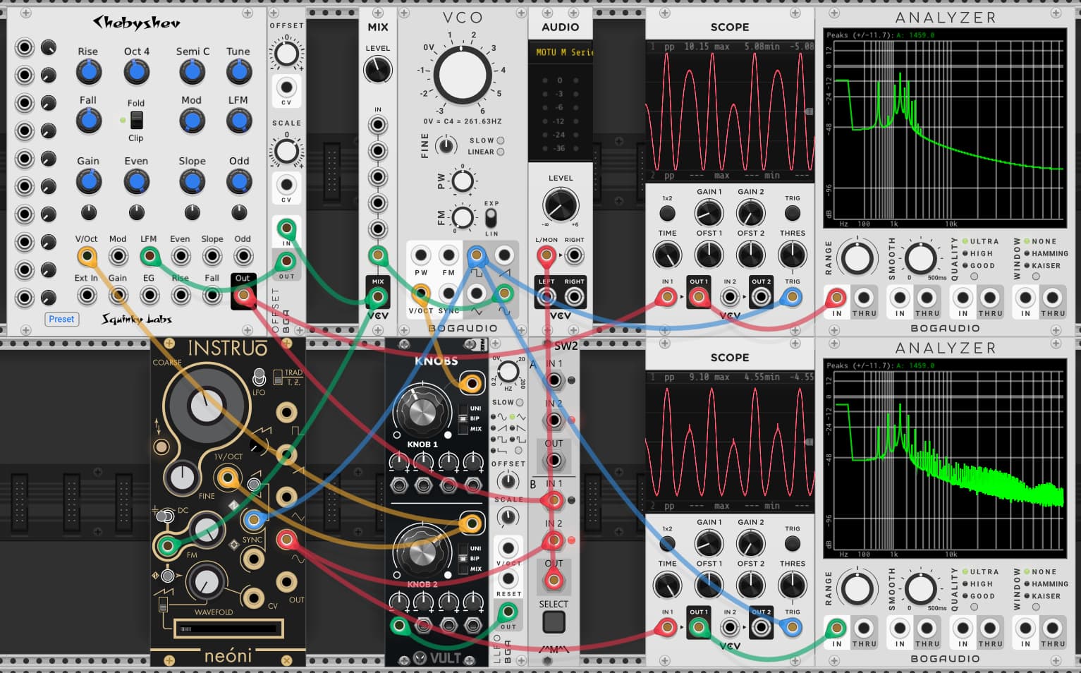
I’m not making a video, but you can play with the patch. There are two key differences as you sweep the carrier frequency.
The Chebyshev grows and folds from two peaks within one cycle, while the Neoni has one of those peaks constant and only folds from one. I’m not sure what accounts for this difference. A wild guess - there is a difference in how the waveforms are reversed/inverted when crossing the zero point?
The Chebyshev has a very smooth wave form throughout the sweep, and a much cleaner frequency spectra. The Neoni has a ton of extra noise, especially at the upper end. If you look at the image, you can see and odd spike at the top of three peaks. I suspect that is the source of the noise. And I am guessing that it may be the result of the Neoni reversing the waveforms at -0.2 volts instead of 0 volts. That introduces some asymmetry. Perhaps there is some additional noise created at the switch point having nothing to do with the -0.2V offset.
2 Likes
Right you are.
I have to confess that the FM in cheby is sort of an afterthought. But the way I remember it is that the FM part is totally simple and standard, the only slighty unusual thing is boosting the FM amount with fundamental pitch to make it sound more “right” to me (more like PM).
I believe that the folder only kicks in when the red light goes on. And the folder isn’t really part of the FM stuff - it comes afterwards, and it’s really on there to keep external inputs from driving the Chebyshev polynomials past one, which would be bad. So the clip/fold it really just that as a “poor man’s” limiter. I think it only kicks in if you use the external input, as I think that’s the only way to get a hot signal in there (in conjunction with gain? I don’t remember).
You could see if it’s doing anything by flipping the clip/fold switch and see if the spectrum changes. If so, it’s doing something.
All this said, I have never heard of anyone using the FM or the external waveshaping inputs of Cheby. I’m sure Cheby is quite excited to be getting this attention.
Looking at the manual, it is also quite explicit that using a lot of the “oddball” features can easily generate aliasing. SquinkyVCV-main/chebyshev.md at master · kockie69/SquinkyVCV-main · GitHub
Thanks for the compliment, btw!
I wasn’t referring to that type of folding. I was just referring to the natural outcome of the configuration of the FM. Try the patch - it is pretty cool. The Chebyshev effectively gets the same sound as the Neoni, but even better to my ears. The Neoni has more options with waveforms, and that can be fun see how they affect the FM. But the Chebyshev has all those different polynomials that can be adjusted, which provides an entirely different variety to the FM sounds.
1 Like
cool! I’ll check it out.
Because I didn’t realize it supports through zero linear FM. I assumed it was like the VCV VCO and stalled. But I suppose it makes sense to support through zero since it is not trying to emulate an analog VCO. Thanks for the heads up.
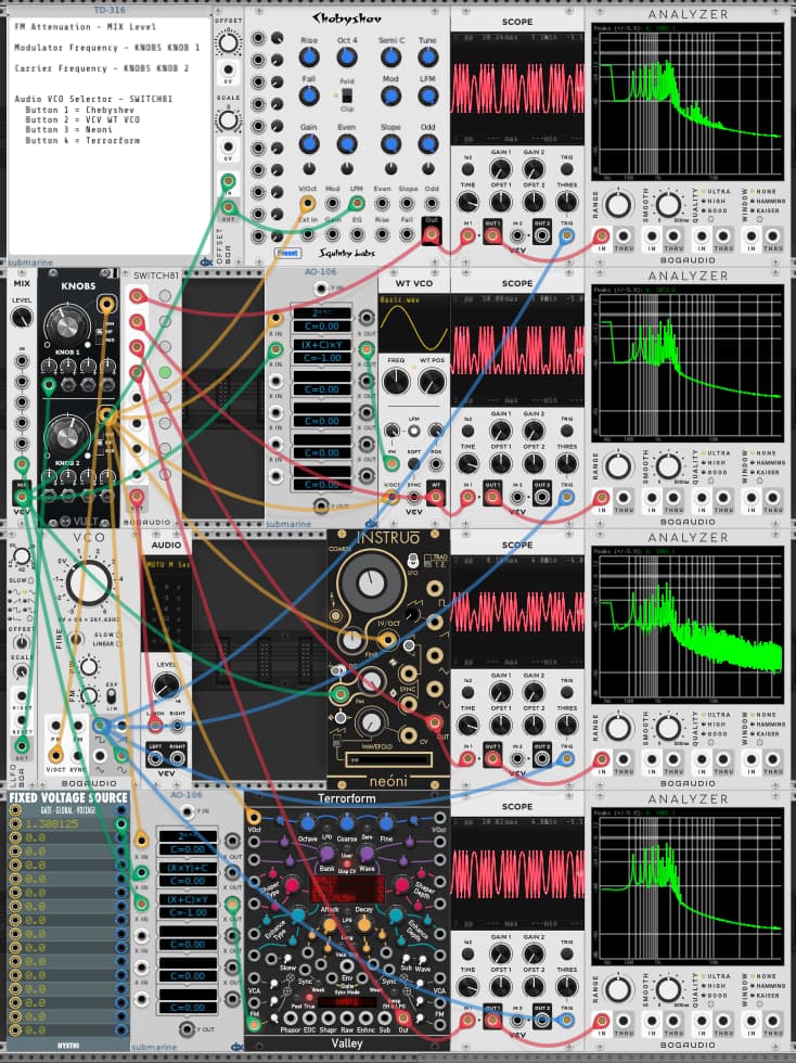
So I managed to figure out how to get the WT VCO and Terrorform to emulate the Neoni through zero FM, making a total of 4 VCOs to compare.
Since the WT-VCO FM uses a constant of 261.625 Hz/volt, and base frequency is 261.625 at 0V, I simply have to scale the modulator signal by a power of two, and then subtract 1.
FM signal = (Modulator * 2^BaseVoltage) - 1
The Terrorform uses 200 Hz/volt, so I need to multiply by an additional factor to scale it to 261.625.
FM signal = (Modulator * 261.625/200 * 2^BaseVoltage) - 1
Here is the patch: Linear FM comparison.vcv (5.6 KB)
2 Likes
Argh, it was the Sync that was stunting the one peak on the Neoni. Once I remove the sync, then it behaves like the others as I sweep the carrier wave frequency. So my 4 VCO comparison doesn’t use sync on any of the VCOs, though all but Chebyshev support it. There is some phase issue between the modulator and carrier that can lead to different sounds for the same settings. The sync eliminates the inconsistency. But it also distorts the waveform a bit as the frequency is swept.
It think it would be worth finding out if the freq stalling at zero is intentional or a bug. I don’t know how you feel about it, but I think it would be “better” if it went through zero. Yes, you are right that the original fundamental was supposed to “model analog”, but not slavishly, I don’t think. Anyway, the old code didn’t have any way of manipulating the linear frequency, so it’s not code brought along from v1. I could be wrong, but I think if that one clamp() function call was removed it would go through zero.
Yes, correct. In Cheby’s defense, it is a very light weight VCO, and most of the features are around the “harmonic VCO” features using the Chebyshev polynomials. Because that was the main use case I decided to “keep it simple” (hah!) and not put any alias control in. It’s very difficult to make the Chebyshev polynomials alias unless the freq is really high, but seemed like cheating to put sync in and let it alias all over the place.
So Kitchen Sink is the one that is “supposed to” be FM with sync, wavefolding, and stuff. It always uses 4X oversampling to keep the alias reasonably low.
Frankly - implementing sync scares me! It took me forever to add the missing sync back to EvenVCO in my EV-3, and even that is a limited implementation. In Substitute the subs are phase synced to the fundamental, and even doing that took a ton of work!
In Kitchen Sink it’s easy, because the whole thing is already oversampled.
Anyway, I’ve really enjoyed this series from you. Tons of interesting stuff.
Great video!
1 Like
Agreed.
As Chris Meyer says “Through Zero FM is linear FM that just works.” I found this very helpful when I was figuring it out: Understanding the Differences Between Exponential, Linear, and Through Zero FM - Learning Modular. The Frap Tools manual (pp10-11) has a good summary too and reminds one that TZFM is something associated with analog oscillators rather than digital FM (which can handle negative values).
2 Likes
Thanks for this interesting video @DaveVenom.
I have not watched Jason’s Neoni video yet, but do you have any thoughts on why the values are 1.08 and 2.1? Is it possible that it this is due to the analog modelling of a real module, where the aim in the circuitry was an ideal of 1 and 2 but the reality 1.08 and 2.1?
That is what I assume. Likewise for the -0.2 instead of 0.0 for the wave reversal. Perhaps he took some measurements from the output of the real hardware and replicated/modeled the digital module accordingly. And who knows how consistent the analog hardware is from one module to the next.
Thanks for posting that link - that is the article and video I had seen before, but couldn’t remember where I saw it.
There is still something I don’t understand from that article/video: " Or…find an oscillator that supports TZFM (starting at 16:11 in the video above) and can indeed go through 0Hz and into the negative frequency range. This means turning around and running backwards when asked. Using our example above, that means turning around going back up to 60Hz, but backwards, yielding the same result as running at -60Hz. Average together 940 and -60Hz, and we’re back to 440Hz. Yay!"
I’m not sure what running backwards really means. At first I thought it was simply inverting (reversing the polarity of) the waveform. But now I’m thinking that the wave form is reflected about the 180 degree phase line (line symmetry, not point), which may or may not be the same as inversion, depending on the wave. Either way, I don’t see why -60Hz would be the same as a reverse waveform at 60Hz.
I guess I need to do some listening experiments to see if/how the quality of the FM output changes as the zero point is crossed.
So after all this, it seems to me there are two common ways through zero linear FM is used. The “traditional” way where the zero Hz point is offset from zero in the negative voltage range, and I guess the claim is with this the carrier sets the base frequency. Then there is the option where the 0Hz point is at 0V, like with the Neoni Through Zero mode. In this mode the modulator sets the base frequency.
Or maybe I am still lost ![]() LOL
LOL
1 Like
I think it is just a case of sin(-x)=-sin(x)
So polarity inversion, same frequency.
That math is only true of sine waves. In general, of course, polarity inversion is not the same as reverse.
Mark Barton, who built the first hardware TZFM oscillator, says that it runs backwards, and that he used a comparator to detect the zero crossing and then a “whole bunch of analog switches” to rewire the circuit to make the oscillator “run backwards”. He has a rather good video with a detailed explanation of the concept on his remodelled Zero Oscillator for a competing virtual modular platform which you can find on YouTube. Joranalogue’s Generate 3 also says on its product page that its oscillator runs backwards for TZFM.
1 Like
Reverse is the same than polarity inversion with sin and cos only, true. I thought it worked like it does in PM, but obviously the implementation has not a lot in common.