Hello,
How to measure the delay between two signals? Typically to measure the same signal before and after several modules due to the « one-sample delay » ?
Of course, note with a scope…
Thank you. Alain
Hello,
How to measure the delay between two signals? Typically to measure the same signal before and after several modules due to the « one-sample delay » ?
Of course, note with a scope…
Thank you. Alain
Are these two identical continuous signals? Triggers?
Can you upload a small patch that demonstrates what you mean? Are you mainly trying to figure out the count of the number of samples?
(To anyone who knows me on this forum, yes, any solution that I’m thinking of will surely use BASICally and TTY.)
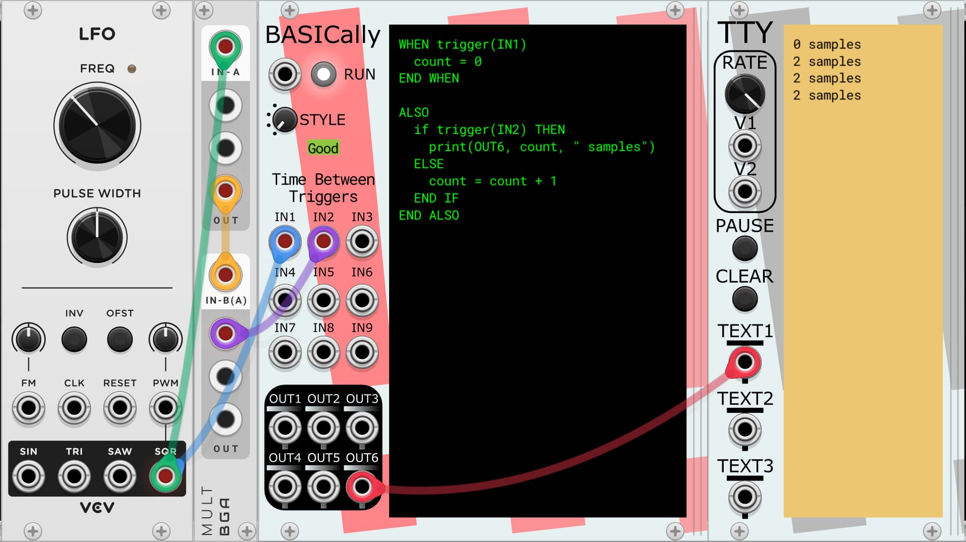
Here’s an example that can measure the number of samples between two triggers, for example.
Time between triggers.vcv (1.2 KB)
But that may not be what you really need. A more specific situation from you can improve this.
mahlen
why not with a scope? There must be a submarine scope that is that accurate…
Thank you for your quick response!
« Are you mainly trying to figure out the count of the number of samples? » Yes indeed. I’m trying to understand and measure the different number of samples when I synchronise clocks and sequencers.
I often use your excellent TTY, but I didn’t think about using it this time… ![]() Thank you for your idea and patch!
Alain
Thank you for your idea and patch!
Alain
I tried with several scopes of course. But on one hand, I have clock signals, and on the other hand, I have the Reset trigger. Visuals, we can see the shift between them, but not precisely.
I would like also to show the number of samples between original signals, and after passing thru different modules…
You know, the synch problem with clocks and sequencers!
Alain
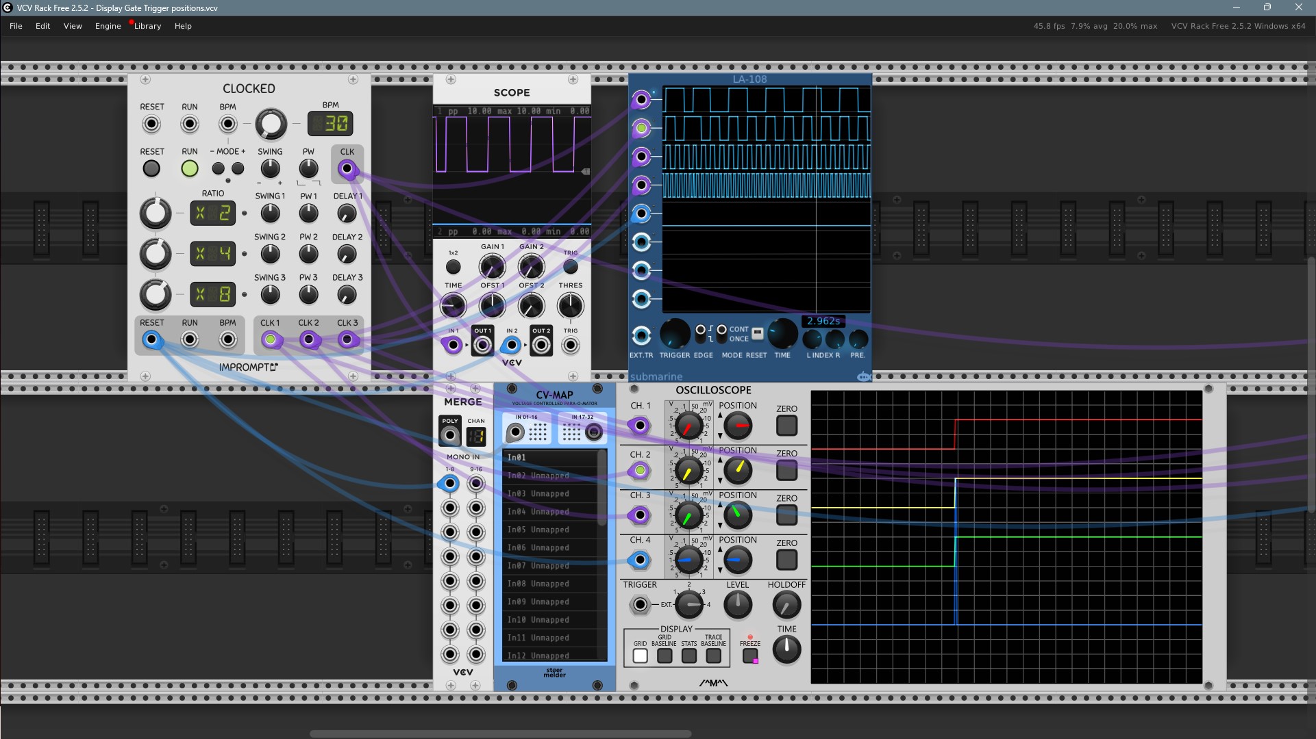
Here is a patch I use to display the relative positions between the Trigger reset and different Clock signals. I use that to explain these mecanismes in videos…
The problem is that there are a hudge requency difference between these signals (clocks signals and Trigger Reset of course). So if I tune the Scope’frequency to display correctly the clocks, and don’t see the trigger.
In addition, I need to freeze these positions on the screen…
Up to know, I’ve fount this solution: I get the Trigger reset in Stoermelder CV-MAP, and freeze th Count Modula Scope. Works!
With the Submarine logic analyser, I can’t see the Trigger. With VCV Scope, I see them, but I only have 1 Clock signal…
That’s why I asked other ways to measure their relative positions. The solution with BASICally and TTY is a great one!
Thank you all for your help. Alain
Display Gate Trigger positions.vcv (2.2 KB)