I am working on a Casio CZ style oscillator.
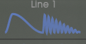
I have already created them for each of the CZ series waveforms separately, but I am banging my head on the wall to implement a feature the CZ had where an oscillator would have two “steps” (see picture attached).
This would be like, for example: one full sine then one full square, then another full sine, then another full square.
I thought about running two oscs in parallel, one with wave A then other with wave B, and make a step counter every time the phase reaches 0 and then select a full wave from each oscillator at a time, but this doesn’t seem to be fine. I wonder if the phase is approximated and sometimes it is not really 0.0f at some point.
Any ideas here would be greatly appreciated as usual.
Sometimes the very beginning of the next step still has some past the tail of the previous one… and weirdly enough, sometimes I just close Rack, open again, and everything is fine.
I will change the step calculation into a zero crossing indeed, this should do the trick.
I may be misunderstanding but it seems you want something like
S * A + ( 1 - S ) * B
Where “S” is a 0/1 square wave oscillator with half the frequency of A and B (that is it oscillates between 0 and 1).
If you do that you will run the risk of having some pretty nasty aliasing effects at the crossover point. So, while I haven’t coded this up, if I were doing this I would make a oscillator which was not a hard square but probably had some slight envelope at the edge (my guess is some sort of few samples worth of sinc at the edge) and then run two of those 180 degrees out of phase at half the frequency and do the above.
Well it depends what you want really. In a continuous form if the match at the flip point you get the harmonics from whichever derivative is not continuous
But you aren’t in continuous form right? You are discretized. So imagine that the cutover point is actually 3/4 of the way between two samples. You want to deal with that aliasing risk.
Maybe I’m overthinking it and I don’t know the code in question but abrupt changes which you force into phase with the sample rate are one of the things that can make stuff sound a bit wonky.
If you think of it as cos(2 pi f(x)) the original waveform (with a single pulse followed by a squiggle) could be something like f(x) = x if x < 0.5 and = 8x if x > 0.5 < 1 type thing. Any of those sorts of tricks would work.
Sure, I’m just saying that since we know those things used PM, and since you could easily do this with PM, it’s a good bet how this was done. And it would allow many other usefully sounds. But you are right - there are a bunch of ways to generate this wave.
Yes … it is the aliasing at the crossover point that I am suffering from so far.
I am still working on it … I put it on the back burner for now until I come up with some clever solution.
Indeed … but I am thinking of a switchable solution (that wave was just one example) where I would actually select the left and the right side of the osc.
Originally I did with two oscillators running on the same phase and frequency, etc. Then every time the phase crossed 0 I would gather the output of one of them for that cycle.
It would work nice and dandy, but from time to time they would somehow drift away from each other (maybe because of precision on floats? dunno).
And aliasing issues at the junction point would appear.
Closing and reopening Rack would, not always though, fix the issue for some time.
On trying to find a reliable way I have actually moved to a single oscillator which swaps between waves on each cycle, but still some aliasing problems would appear over time.
My guess is on loss of precision … but I still need to research more.