Looking for help making a 3D rotation patch for vector synthesis on oscilloscope.
I don’t think I fully undestand what you’re looking for…but this could be a good starting point ![]()
1 Like
Yes, specifically take a look at my 3D oscilloscope module Sapphire Tricorder, with Tin placed to its left. Tin allows you to send any 3 input voltages into Tricorder to be graphed in real time.
Below is a demo video. Starting at 3:17 is where I show how to use Tricorder’s controls.

5 Likes
hi ! i just sent you a message, i’m hoping there’s a way to send XY to a scope to create 3D images presented in a 2D space like a scope. is there something simple i’m not realizing about your collection that allows me to plug into a scope? this would be such a great compliment to the rest of the scope art i make
I’m not sure, but I think you are asking how to take software-generated signals and convert them to analog voltages to control external hardware? Is that correct?
If so, have you tried using an ordinary sound card with analog outputs? There could be a few issues:
- You would probably need a Surround Sound capable sound card, because most will produce only two channels (stereo).
- You will have to make sure the output allows very low frequencies without filtering out DC.
It sounds more like a hardware problem than a software problem, which means I’m not sure I understand what you really want. Perhaps others reading this post can help…
no i have all that already. i just dont understand how to display what the tricorder displays, on a scope. for example, if i take two outputs XY from one of your other 3D modules, and plug it into a scope, either a vcv scope module, or my hardware scope using dc coupled outputs, it doesnt display the same thing as the tricorder. the tricorder has three inputs, but it displays the 3D image in a 2D space just like an oscilloscope, is there any way to achieve this? perhaps even with a new module? would you be open to a commission to such a thing? there’s probably ways to do this with lots of multipliers, or math modules, but i have a hard time wrapping my head around it, which is why your modules appealed to me, it seems like there is just one piece of the puzzle missing. the tricorder already has an oscilloscope screen type of display, how difficult would it be to send the tricorder display as an XY out to a “normal” oscilloscope module/hardware scope?
how would a VCV patch for this go?
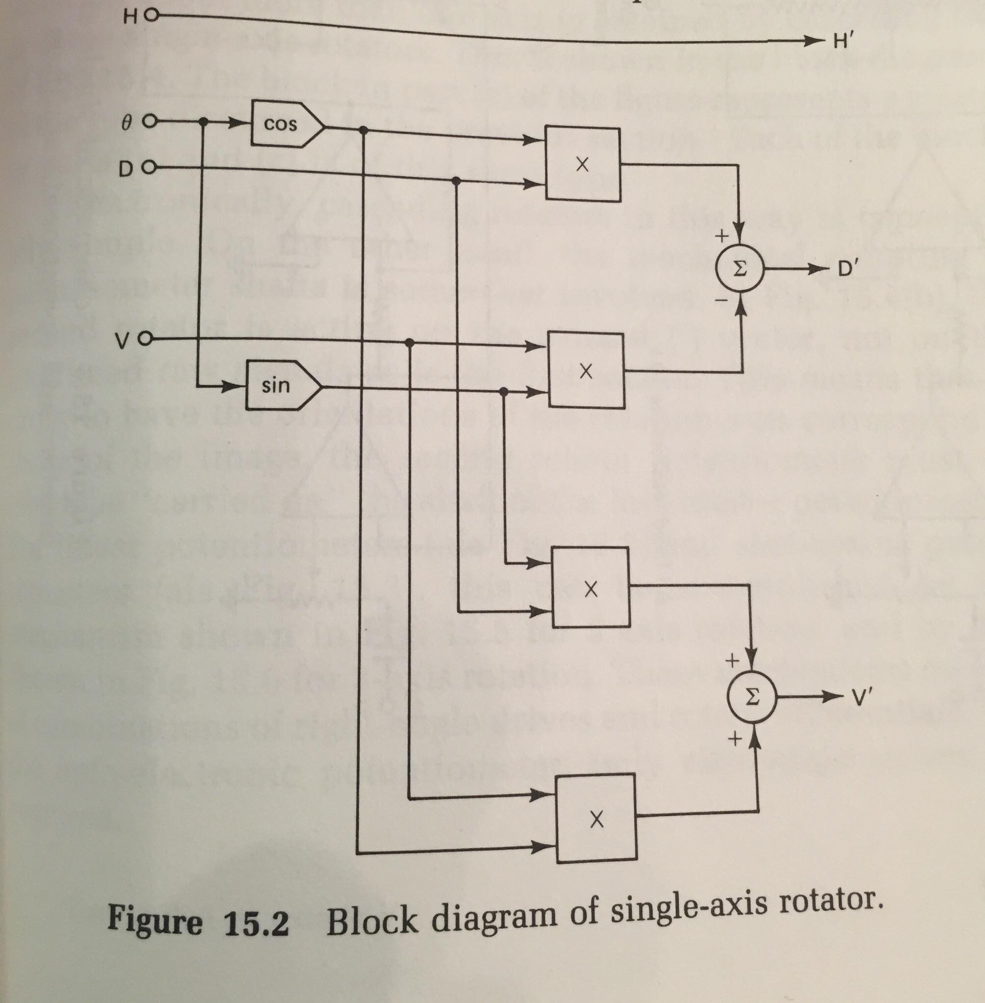
3D with your analog synth. This would require a quadrature source, four analog multipliers, and two summers (mixers) for each axis of rotation. Note that one input to the D’ summer shown is inverted.
Source: H.B. Tilton, The 3D Oscilloscope (1987)
could this be done with the BASICally module? @StochasticTelegraph
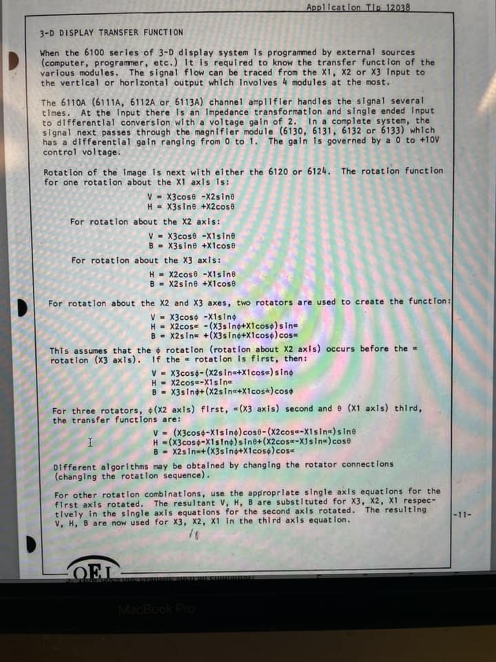
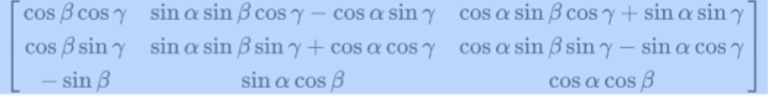
I guess I should try patching this myself, i just don’t understand the math symbols. But I understand that I need quadrature oscs, lots of befaco abc modules, and maybe an interesting wave shape for the input. I just don’t understand the symbols in this math formula
1 Like
One thing you could try with existing software is to use my Pivot module to rotate a triplet of voltages representing a 3D vector around the axis (1, 1, 1), then keep only the X and Y outputs from Pivot to feed into a 2D scope. Something like this:

Here is the patch if you want to play with this idea:
pivot_demo.vcv (2.0 KB)
2 Likes
Doing matrix math in BASICally would be challenging. I won’t say impossible yet, but, yeah, I’d try Don’s Pivot for a while before attempting this in BASICally.
1 Like
Thanks!
Hello @zakforrest! Please tell me if you still have the book “The 3-D Oscilloscope A Practical Manual and Guide”? I really needed it for research but I can’t find it in the public domain/library and I can’t buy it. If you have the opportunity, could you take a photo of each page and send it to hlobaanton@gmail.com, I will be extremely grateful to you!
Welcome to the VCV community! If you want to reach out to someone specific, type an @ before the name. there will be a notification send. @zakforrest (done now)
1 Like
sorry, i do not have (welcome to vcv community ![]()
1 Like
@hlobaanton you can get the book from libraries
Thank you, I will try to ask about this method in the library of my institution.