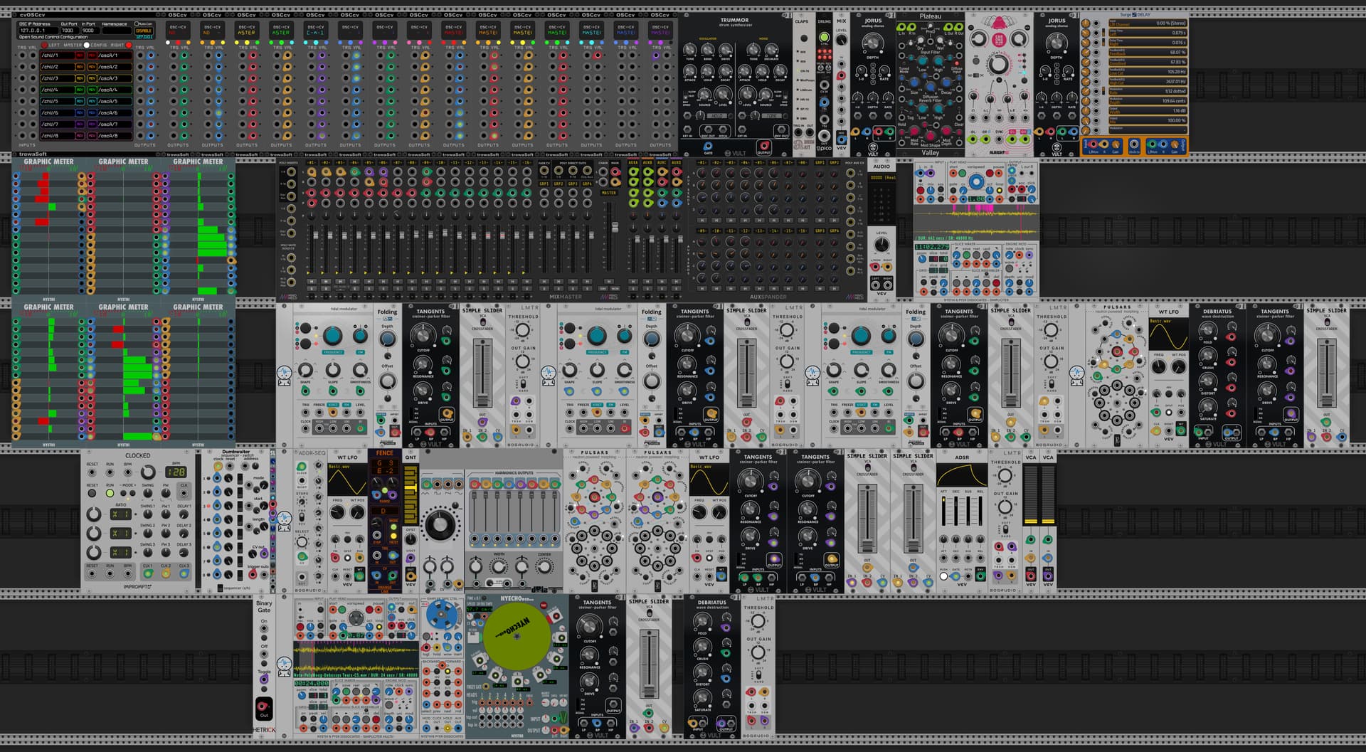
Have been using my various midi devices as input (CAD, game engine, software synth, Processing graphics) for a number of years now, developing strategies to enhance the resolution and alter the usability of the physical controls. This video shows the modifications to an AKAI APC40 MKII controlling VCV Rack.
The endless encoder caps have been designed to allow fingertip control through an off-axis bearing mounted “crank”, like a mini-jog wheel. This allows for multiple controls to be manipulated with each hand. Resolution is currently set at 0.0005 units at the lowest RPM.
The faders have an add-on engineered mechanism that returns each fader to the center position, lightly spring-loaded up and down. Fits nicely into the 4mm recess of the AKAI. This allows for applying unlimited banks of faders to a fixed set of hardware controls, and fader automation in software, without motorized control. The fader caps have been redesigned to have radial surfaces to make the action of pushing and pulling uniform. The increment/decrement approach works well for the way I use it.
All of the modifications are 3D printed.
The midi stream is sent to Processing where it is handled and converted to OSC and sent to VCV Rack. Velocity sensitivity is variable, mins and maxes are variable, and everything can be stored as a text file for reloading in another session.
Would love to hear what you think about the approach!
8 Likes
Do you like to share your 3D design for the endless encoder caps?
Brilliant!
I imagine the amount of effort going in to this … just setting up the cvOSCcv ports… or perhaps you made something clever for that in processing too ?
I would love to see the processing sketches.
1 Like
I’m trying to decide whether to pursue as a product. In exchange for evaluation and feedback, I’ll send you a few 3D printed caps no charge.
Jens, thanks! The code has evolved through a number of applications and has a lot of orphan lines in it currently, sure it’s not very legible. I’m happy to explain the approach though. Will detail it in another post.
The cvOSCcv routing is a real nest of wires, but all a repeat of a single circuit. The NYSTHI meters a great way to see the interaction and identify a route.
Each circuit through Processing is similar, stored in a FloatDict (dictionary array) with matching StringDict for labeling on the display.
1 Like
I love hardware motorized controls. That is why in my Meander module I have all knob parameters virtually motorized such that CV input rotates the knobs. A lot of people do not like what I have done. Apparently auto-moving controls freak people out 
I like how you have emulated motorized controllers without motors.
2 Likes
agreed that virtual motorization should be standard, it’s cruciali to learning a system with live CV control.
1 Like
Motorized knobs are fine but it doesn’t always work with the way some people think about cv, the idea being that you are modulating the value of the knob, not “virtually turning” it. It makes a difference if you want to turn a knob while you’re modulating it.
2 Likes
FWIW if you are emulating real world tech that deeply then why not model something like the endless encoder knobs on the Hydrasynth where values are indicated on a ring around the knob and so having them instantly set to a new value doesn’t ruin the paradigm so much.
I believe is pretty much what @Patheros and I tried to do with our module ChordVault.
With the sequence modes where the module or CV completely takes over step selection, the knob is animated.
With the OFFSET button engaged there is a need to be able to turn the knob manually. So we additionally created a white indicator line (aka ring) showing the range of steps currently „active“.
I thought this hybrid behavior would be confusing or just plain weird. Happy to report there was no such feedback and from my own heavy usage over the last months I can say it never felt like something getting in your way and the knob was always clear to me.
1 Like
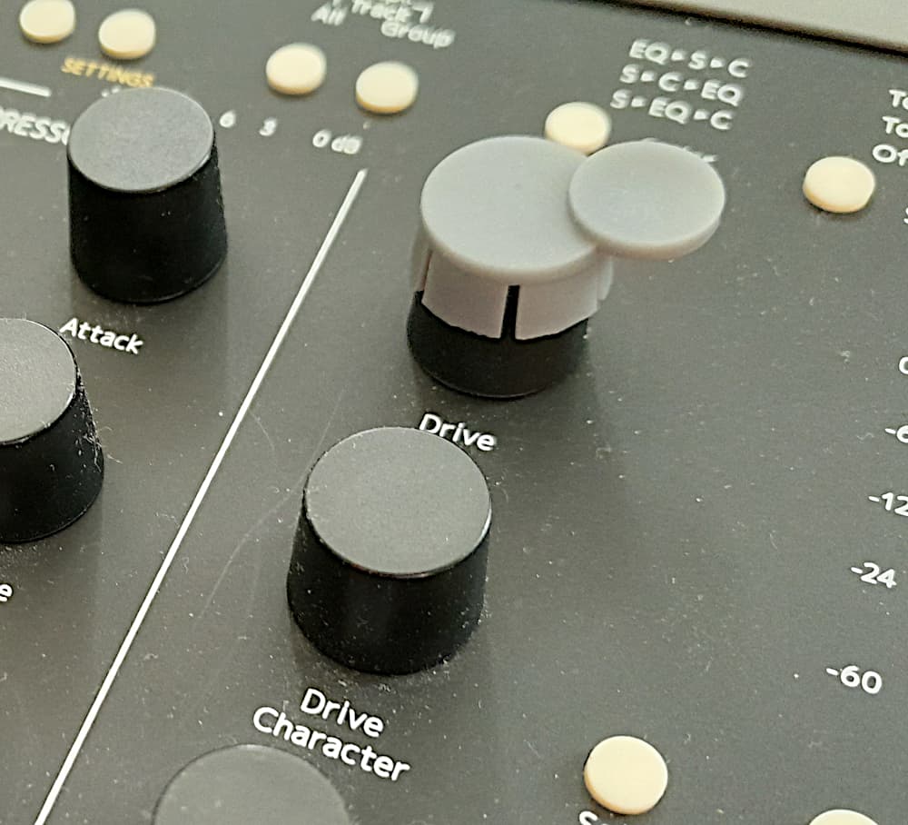
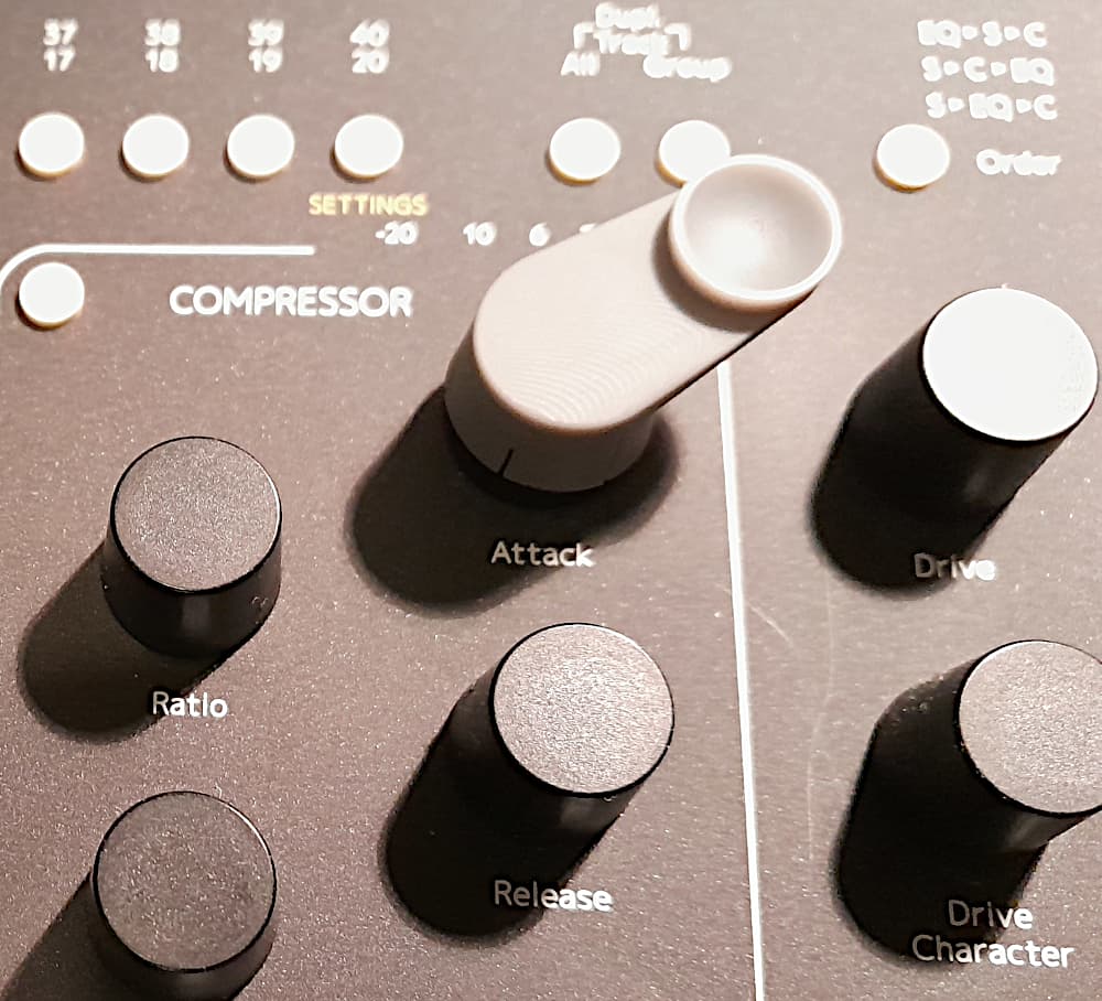
I made a cap that fits on top of the caps on Console 1, but the knobs on Console 1 are too stiff so that turning a knob with only one fingertip doesn’t work well.
2 Likes
Some encoders are stiffer than others. that being said, the flat design requires more friction downward to spin, cupping the shape will help.
I have wondered about the old DJ trick of spraying contact cleaner into the encoders to wash out the grease and leave them more free spinning. The ergonomics are different when not gripping and twisting.
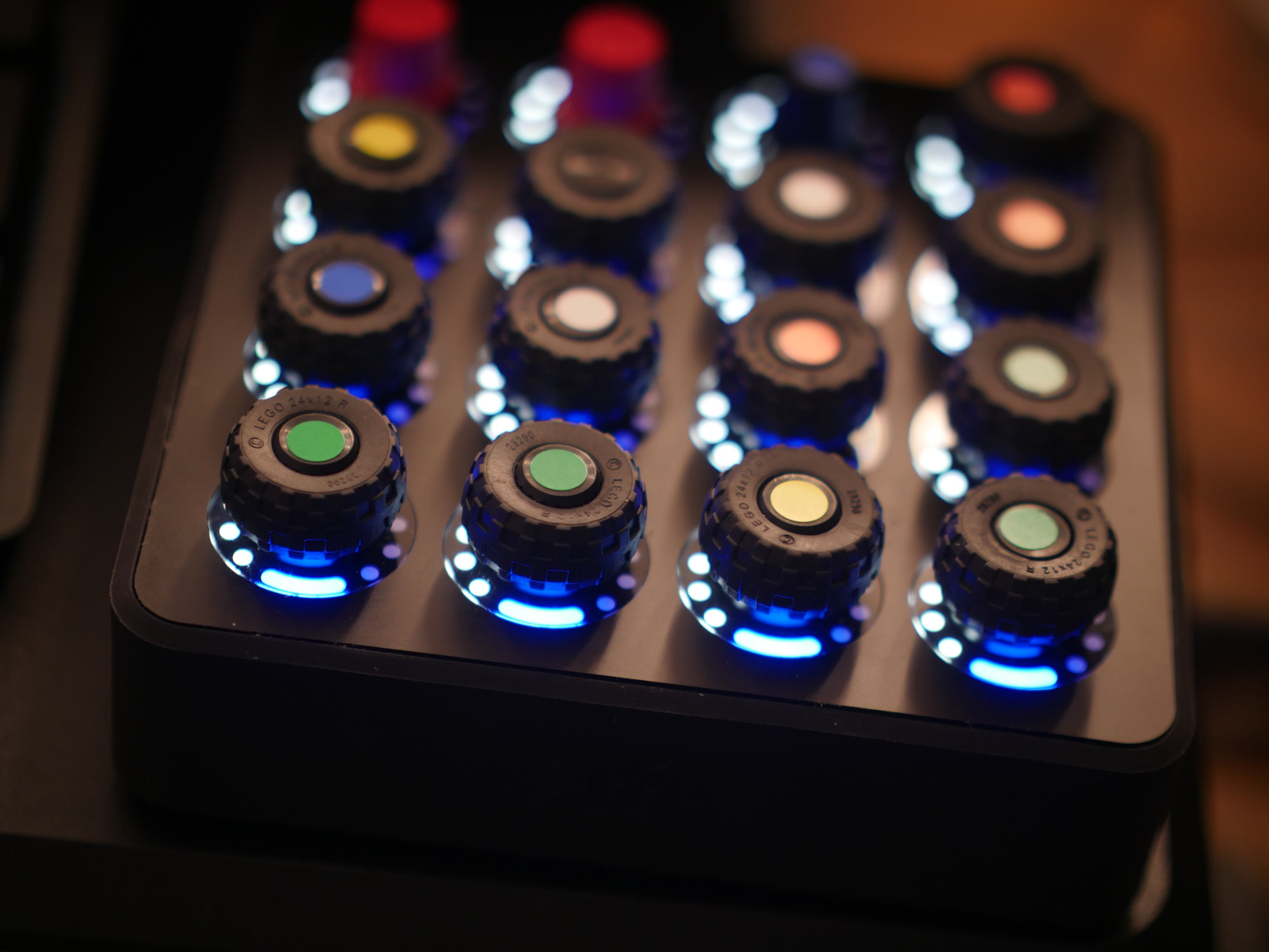
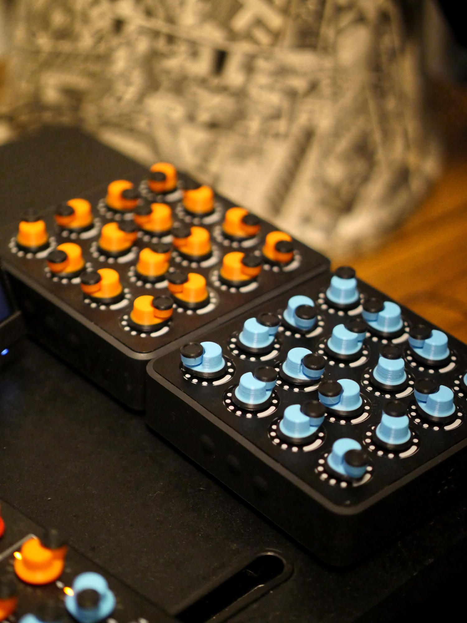
Here was my design progression, from stretching LEGO tires around the existing caps, to CNC acrylic disks to be able to shine the LEDs through, to the initial flat 3D printing disks (similar to where you are in your model)
LEGO tires, bought in a bulk bag, had the MFT and the APC fitted out. Worked well for spacing and a proof of concept, lots of friction when looking for high RPM turns.
CNC lathed acrylic disks, and used this setup for a long time. Downside, friction and conscious control for the radial movement needed.
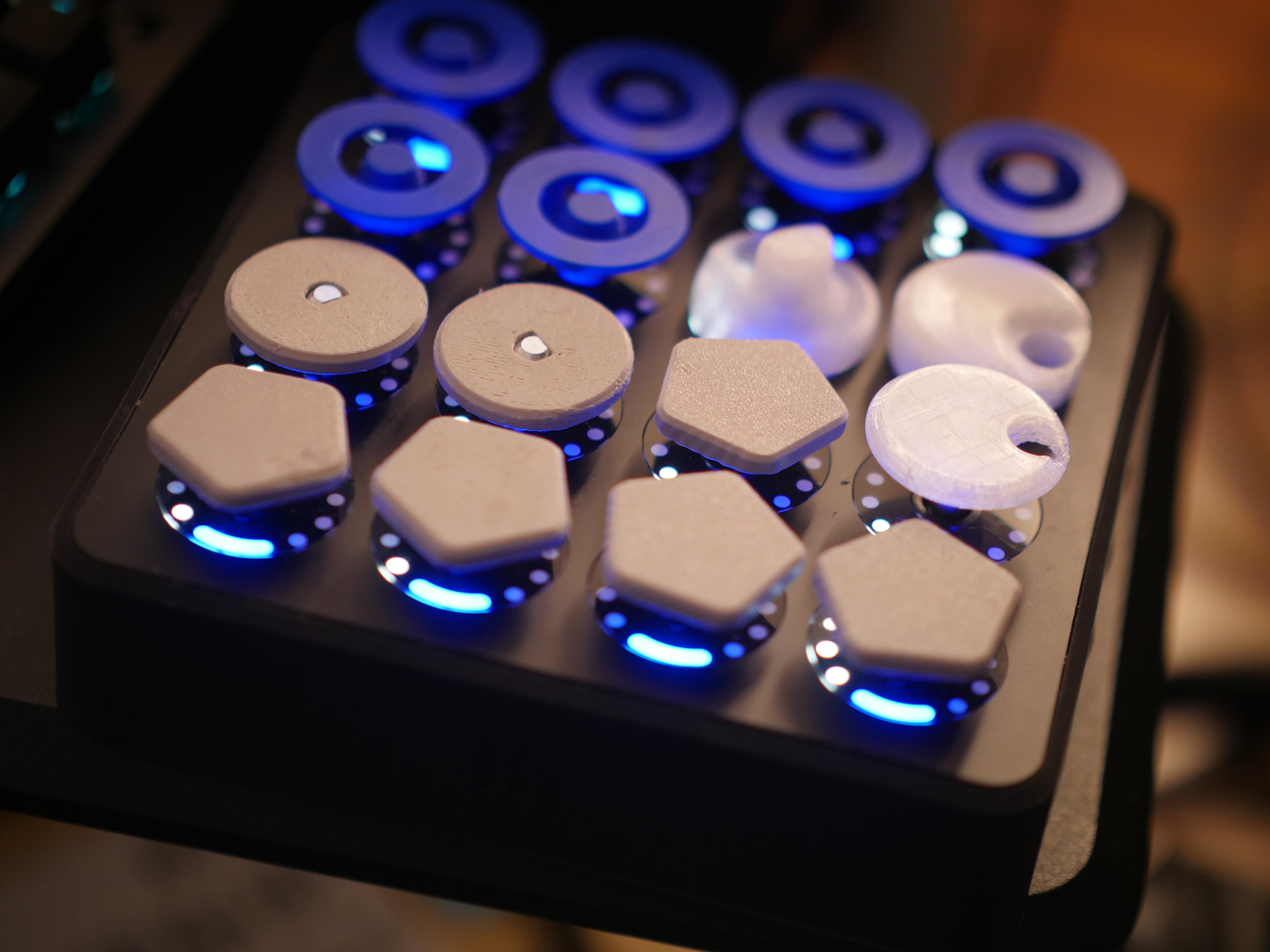
Platter style 3D cap toppers. Quickly realized the need for an index.
Added rotary index holes, first three, then six holes, to allow faster locating. Works to get more force on the axle, fingertip pad positioning and the resulting rotating friction is not ideal.
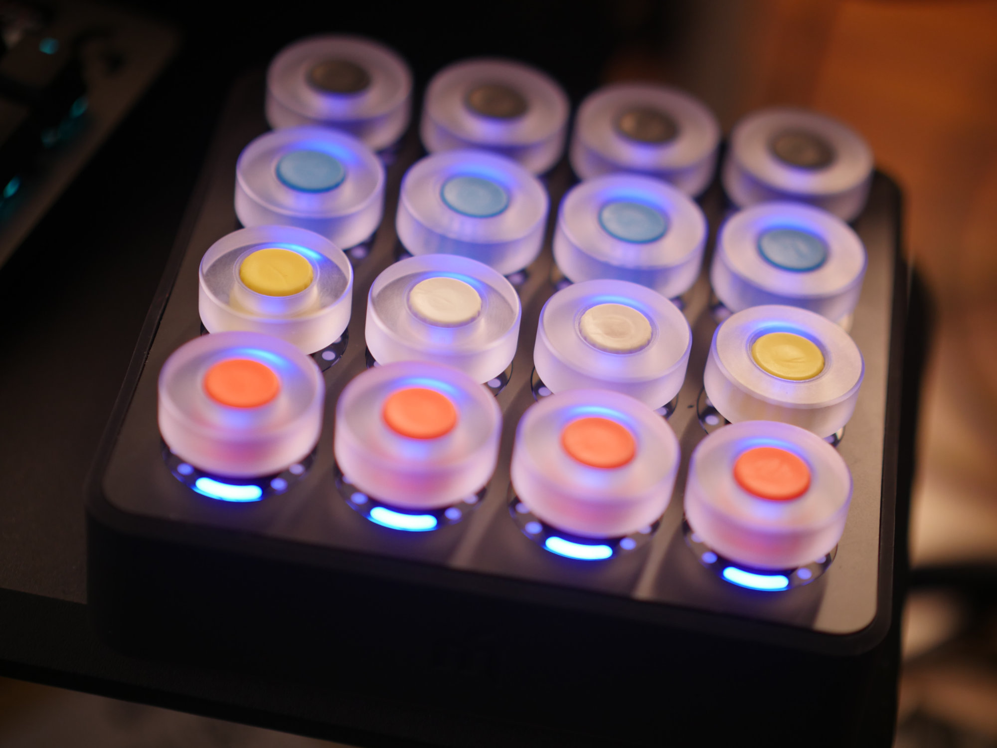
The final monolithic solution, five spacing gives a good-sized index hole.
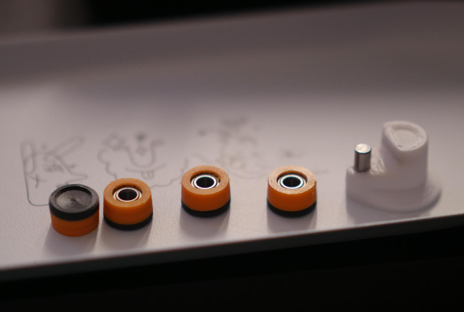
About a dozen bearing variations, layout, height, bearing nesting, and tilting of the axis inward and outward.
Current stable design.
4 Likes
I assume the eccentric part of your knobs can spin.
Yes, sealed precision bearings are over-molded in the 3D print. Fingertip pressure is constant, all force is acting radially.
3 Likes
This is a serious solution. I didn’t expect that. Great work!
2 Likes
I made a 2nd attempt and it works fine:
2 Likes
Cool. Cup rotatation will reduce friction and improve the feel.
2 Likes