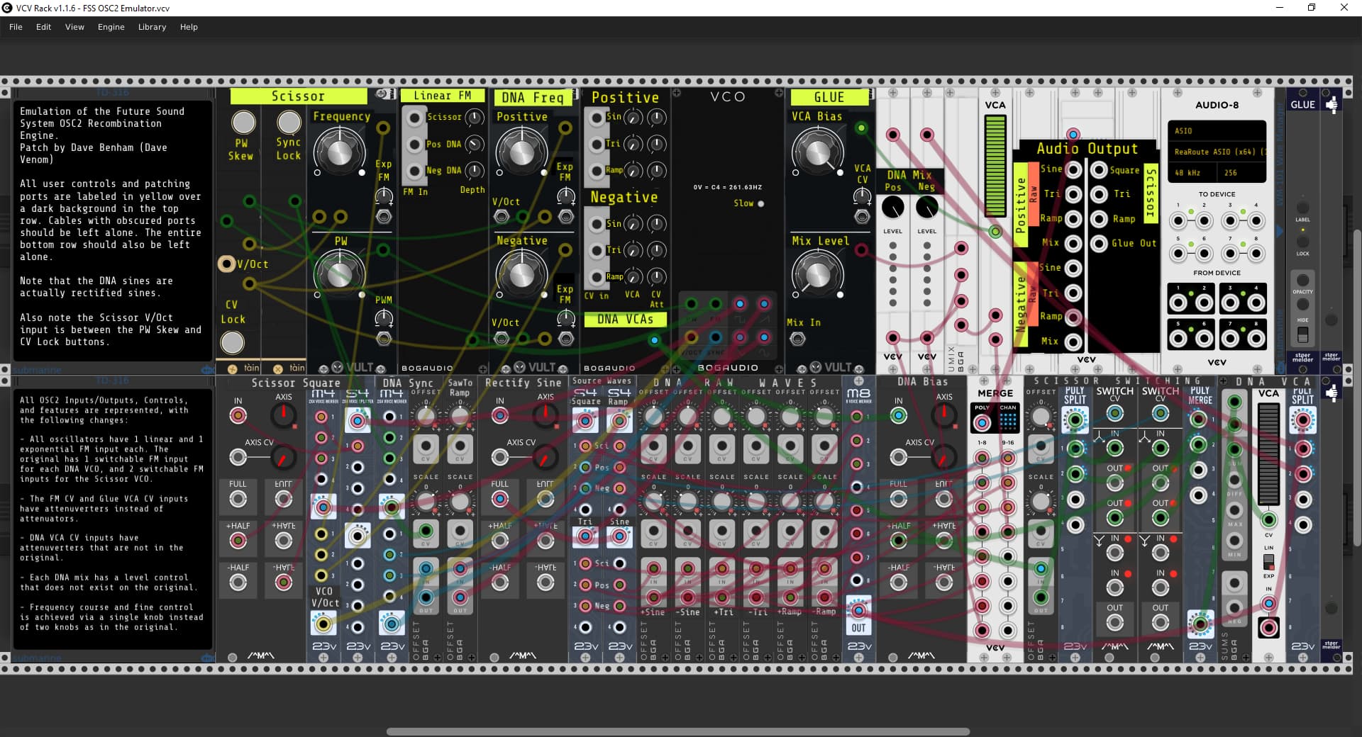
Good, I’m glad you looked at my emulator.
Yes, the DNA mix and GLUE section was the hardest for me to understand. I spend a long time studying the DivKid video to get an understanding. I’m pretty sure the Pos DNA signals are initially simply summed to provide the Pos mix. At some point it likely needs to be attenuated, as that can exceed 10 volts. The same for the Neg. I don’t know if the attenuation occurs in the DNA mix circuit, or the GLUE, or both?. However it is done, the OSC2 seems to have a fixed algorithm. I use the poly VCV Sum to mix the 3 DNA signals (sin, tri, ramp), and thought, "Why not give the user the ability to control the attenuation and mix ratio of the Pos and Neg DNAs.
So in the GLUE, the incoming Pos and Neg mixes are mixed at a fixed ratio, and then the “Mix In” gives you the opportunity of mixing in a 3rd signal. The Mix Level attenuates the “Mix In” before it is mixed with the Pos/Neg mix. The final mix is then amplified by the GLUE VCA , which has a VCA CV input with a depth control (attenuator), plus a VCA bias. I use an attenuverter instead of an attenuator for the CV depth control.
I’m pretty sure the PW skew preserves the waveform within the pulse window as it is stretched or shrunk. It took a while, but I finally figured out the Log2 math. Assuming I have bipolar -5 to 5 volt CV controlling the PW, call it x, and the PW duty cycle varies all the way from 0 to 100%, then the Pos V/Oct delta is -(Log2((x+5)/10) + 1), and for Neg it is -(Log2((x-5)/-10) + 1). But for the Bogaudio VCO the PW ranges from 3 to 97%. So the formula is adjusted to -(Log2((x+5.3)/10.6) + 1) and -(Log2((x-5.3)/-10.6) + 1). I’ve got a modified version of the emulator that preserves the waveforms perfectly as they are expanded or shrunk. Assuming PW goes from 0 to 100, the formula exactly halves the frequency (doubles the wavelength) of the stretched DNA signal. Conversely the shrunk DNA frequency goes down 1 octave at 25%, 2 octaves at 12.5%, 3 octaves at 6.25%, etc. And then just as the width goes to 0, the frequency becomes undefined (infinity) which makes sense.
The other thing I struggled with is the exact configuration of the DNA waves. The FSS Molton Modular video confirmed for me that the DNA sine is actually fully rectified. So assuming the Pos and Neg are at the same frequency, then the rectified sines are mirror images of eachother, but effectively at double the frequency of the base frequency. My understanding is the triangle waves are also mirror images, but not doubled. When I scale and offset the triangle sources to get the Pos and Neg, it messes with the phase, so my triangle starts at 2.5 volts instead of 0. I discovered I can get the Pos and Neg triangles with the correct phase by rectifying a ramp instead, but that introduces a horrible high frequency buzz at the triangle peaks that is an artifact of the anti-aliasing signal at the source ramp discontinuity. So I am sticking with the out of phase triangle for now in my emulator. Based on the graphics on the OSC2, and also from what I can see in the videos, the Pos and Neg ramps are Not mirror images, but rather true ramps that move in parallel.