It is easy if you are smart, haha. But I am not smart, so I mess up every time and then I am trying to fix it. Well, that’s how people learn, I think… But I still mess up even things that I already know, like the virtual ground thing. i already had this problem. And quite recently… I think it was with a comparator in a sequencer… There was something wrong with the reference… I don’t remember. Anyway, thanks for kind words! Perseverance is indeed what keeps me going.
Hi! Alright, straight to new stuff, which is not a lot, but all very interesting! So I like reverbs and I have a guitar pedal reverb and Alesis Midiverb thingie and I used to have a dedicated guitar multiFX unit that I used for reverbs only, cause all the overdrive/distortion and even delay-based effects were bad, while reverb was passable. Anyway, a year ago or maybe even more I decided to make my own spring reverb. Like from scratch. Then I realized that to make a spring tank I would have to make a box and maybe suspension and also wind the transducer/receiver and mount it all in the said box and this and that… Meh. It’s better to just hunt for an old radio that has this reverb included. There are some radios of this sort, in post-USSR lands. One of them is Gaina (Гайна Р-301Л) and I didn;t really hunt for it, I was just waiting patiently, and then it appeared and I bought! And it turns out that’s actually Гайна Р-302Л, so basically the same thing but without a reverb. Well, I gutted it, leaving only the amp inside. And now I have a tube amp. And I already had it last time I wrote a post here. Maybe even before that, I bought it less than a year ago. I was tinkering with it, cause it’s not too loud, I would even say, it’s pretty quiet. And I was trying to mod it, so it would be louder. With no results at all. But it works… My fear is that it’s physically impossible to make it louder (I think the power transformer’s highest winding is ~260V or less and most of the tube guitar amp schematics I saw for reference are using 300-320V windings for the output tube plate…). And the biggest problem is that even though I kinda grasped the basics of solid-state electronics, tubes are just… I don’t get it. Alright, back to square one.
On october/november I made a box. It was a great box! “Wow,” - i though, - “I made a box”. About a month or two before that in my local DIY electronics store I saw an owner just destroying dismantling small transformers with laminated cores. I asked if I can have the cores, and he said that they were about to throw them away anyway. “Wow,” - i though, - “I bought the laminated core plates”. So I made another box, this time I was keeping in mind the idea of making a spring tank. And I made it, it was even better than the last box. Objectively it’s like 4/10 woodwork, but I was proud! Then I wound…winded? I made a receiver coil using a 0.1mm wire, which was an actual bottleneck of a project, meaning if I can’t make it, there’s no point. I can make a transducer, I know that, it’s not hard to make a magnet go “boing~”. Receiver though is… at least in my mind it was much more delicate, I guess. Maybe I am wrong. But I made it and I checked it with my oscilloscope to see if it actually works. And it does, I was plucking a string with a magnet attached to it and I saw a very strong signal on the scope. Not just 1mV or whatever, but something like 30-50mV. So I quickly made a transducer coil and waxed it all, just for funs. And mounted it into my box. I used old heater NiCr springs for testing (y…y-yeah, not that I hoped they would work and I wouldn’t have to buy springs…). And here, look
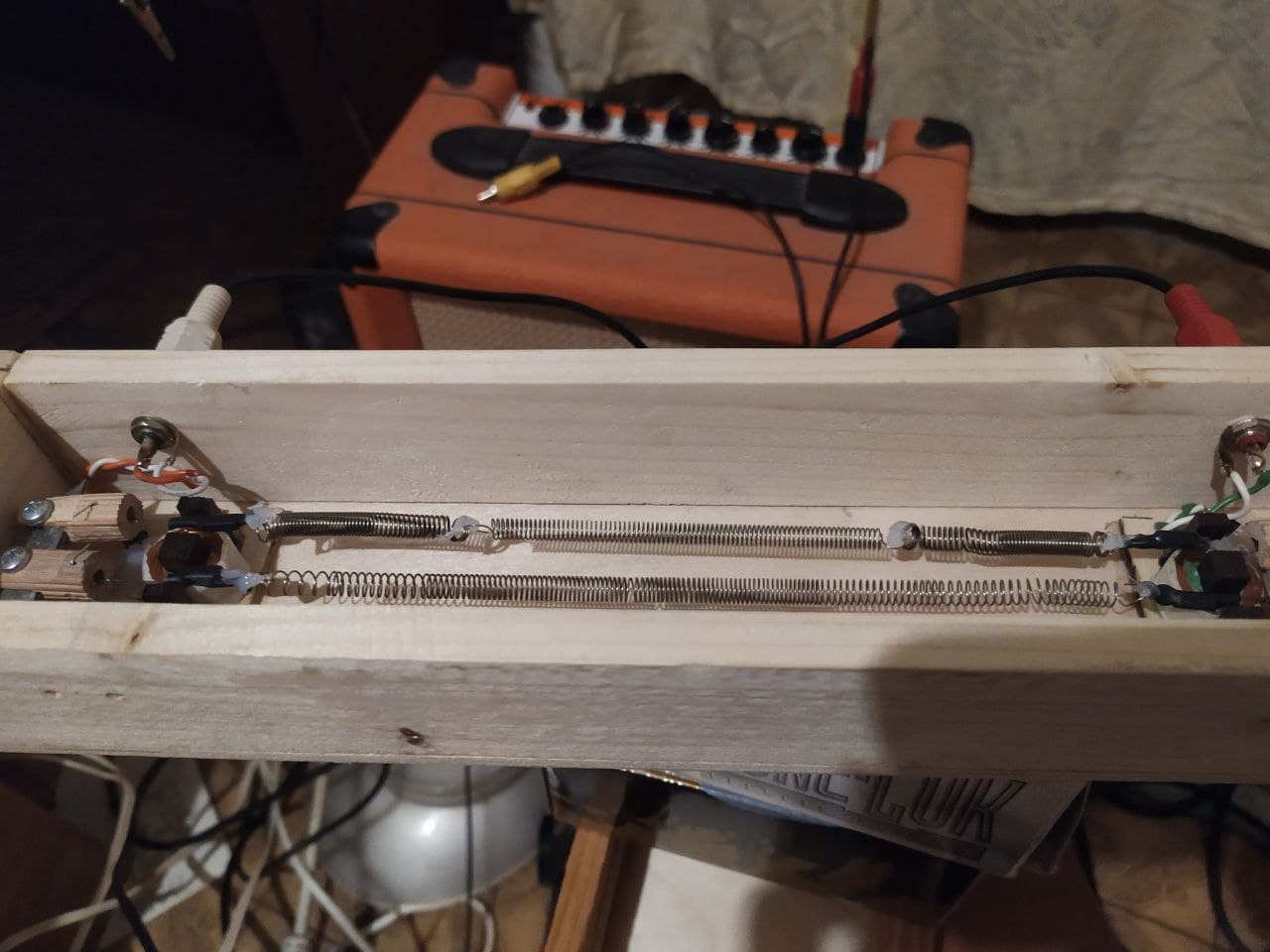
It worked, btw. I know how it looks, but it actually produced reverb! It was noisy and distorted and… my way of mounting springs was bad, and for some reason one spring was reacting more than another spring, and I used neodymium magnets that I put in a heat shrink, so they always found a way to stick to the transformer coils, but yeah, it worked!
Well, it is great that it worked, but there were lots of troubles. And while troubleshooting I used my tube amp. And I destroyed it. Haha. I blew up my output transformer somehow. It’s not hard to buy a new one. But I decided to fix it maybe. It’s like 2700 turns of 0.1mm wire for the primary, but oh well. So I unwinded… unwounded? The secondary and here it is, the burn mark.
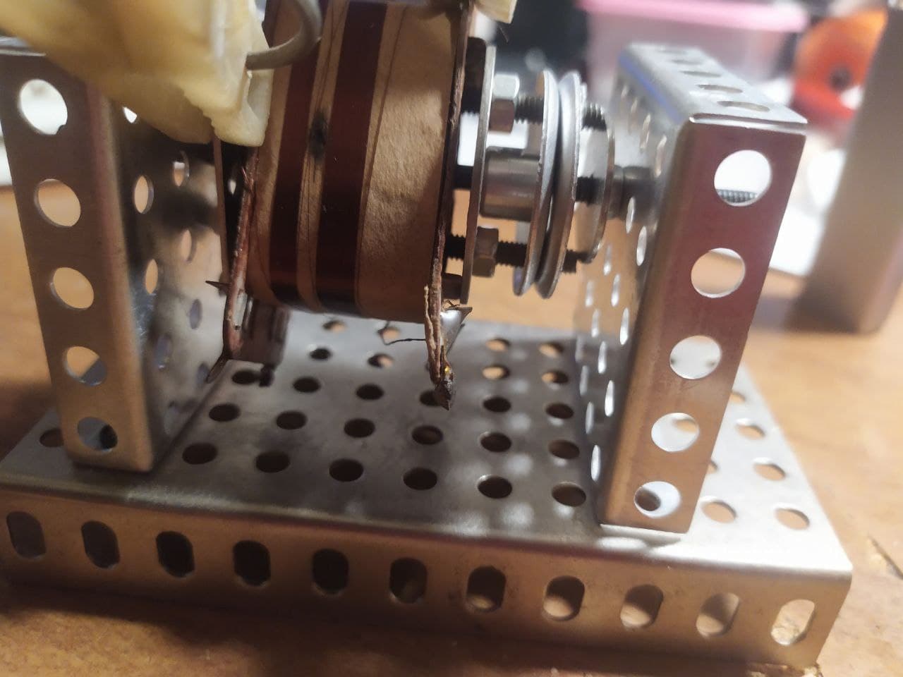
Luckily, it affected just maybe 20-30 turns. So I removed them (you can see it on the photo, it’s after I removed them) and soldered the remaining unaffected halves together. I put a small paper thing under the repaired spot, cause I think maybe copper was pulverized and maybe there is some copper molecules where the black spot is, and I haven’s looked under this spot… There’s a whole layer of 0.1mm wire underneath. If it is somehow bad too, it would probably be better to buy a new transformer. But it works. I tested it. By the way, I fixed it last week. So for a couple of months I was using another amp, this one is solid state guitar amp, a cheap combo drive or whatever you call it. You can see it on the background on the photo above.
Alright, I was fixing my spring reverb and suddenly I just decided to make something out of… some kind of MDF support/whatever-it-is that I found on the street and an old alphabet board for magnetic letters, I remember using it when I was a kid…
Look
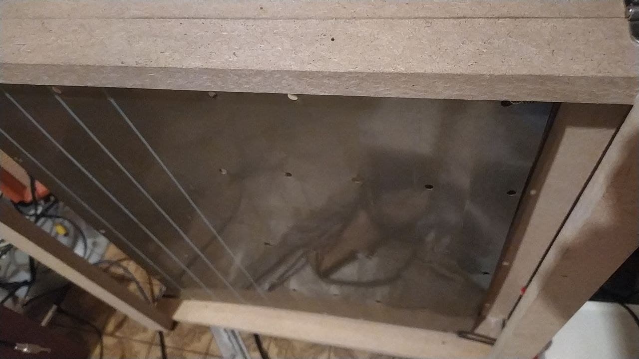
Yep, a plate reverb! This one don’t need any esoteric explanations. I just glued a speaker on the back of this thing and put a couple of piezo microphones. To drive the forementioned speaker I bought a TDA2030 kit. Which, by the way, is the first kit I ever bought… It works! Somehow it’s muddier than my spring reverb, even though this bar is very low, it managed to limbo dance under it. I think the metal is bad, it’s a cheap thin plate. I might do something with it later… Or might now, haha. We’ll see!
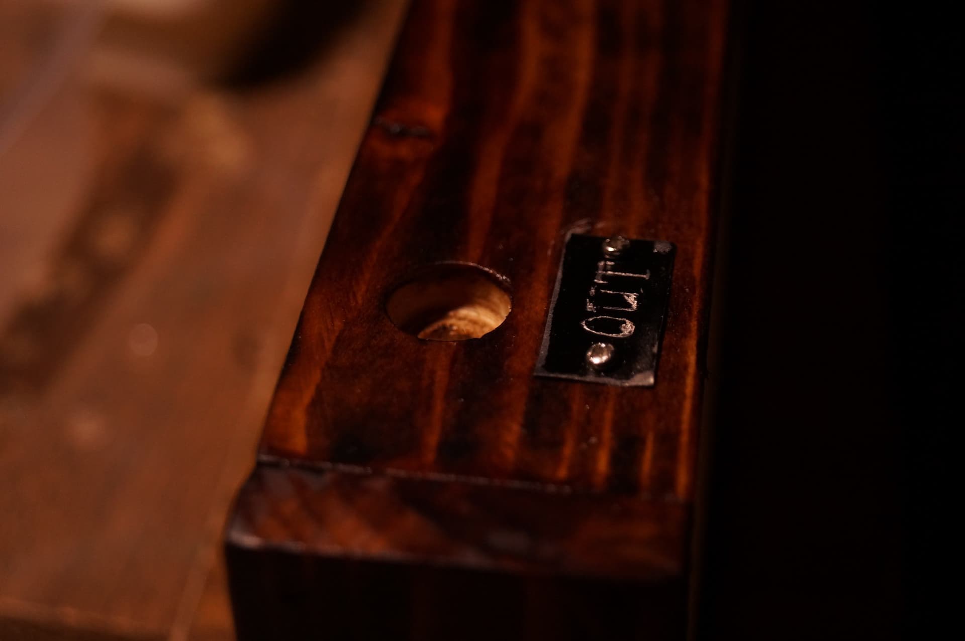
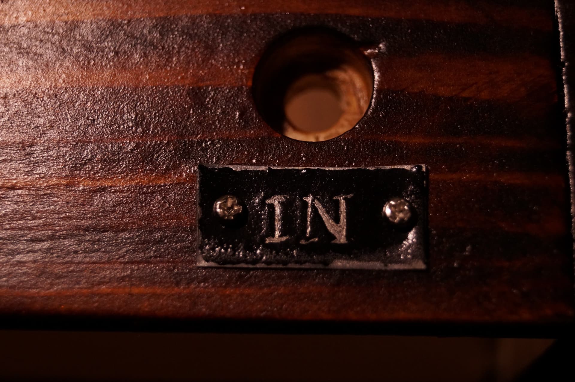
Now, the spring tank was hard to fix. I mean, fix all the problems, like with escaping magnets and moving springs… Like I couldn’t fixed the springs so they would hold the magnets in the gaps of E-cores. So I just demagnetized the magnets by blasting them with hot air out of my heat gun (I also changed the way of attaching them to springs, I used a gel pen tube or a stem or whatever you call it, haha) and redid the way of mounting the springs. I also bought other springs, And stained the wooden box… and made engraved plates for IN and OUT.
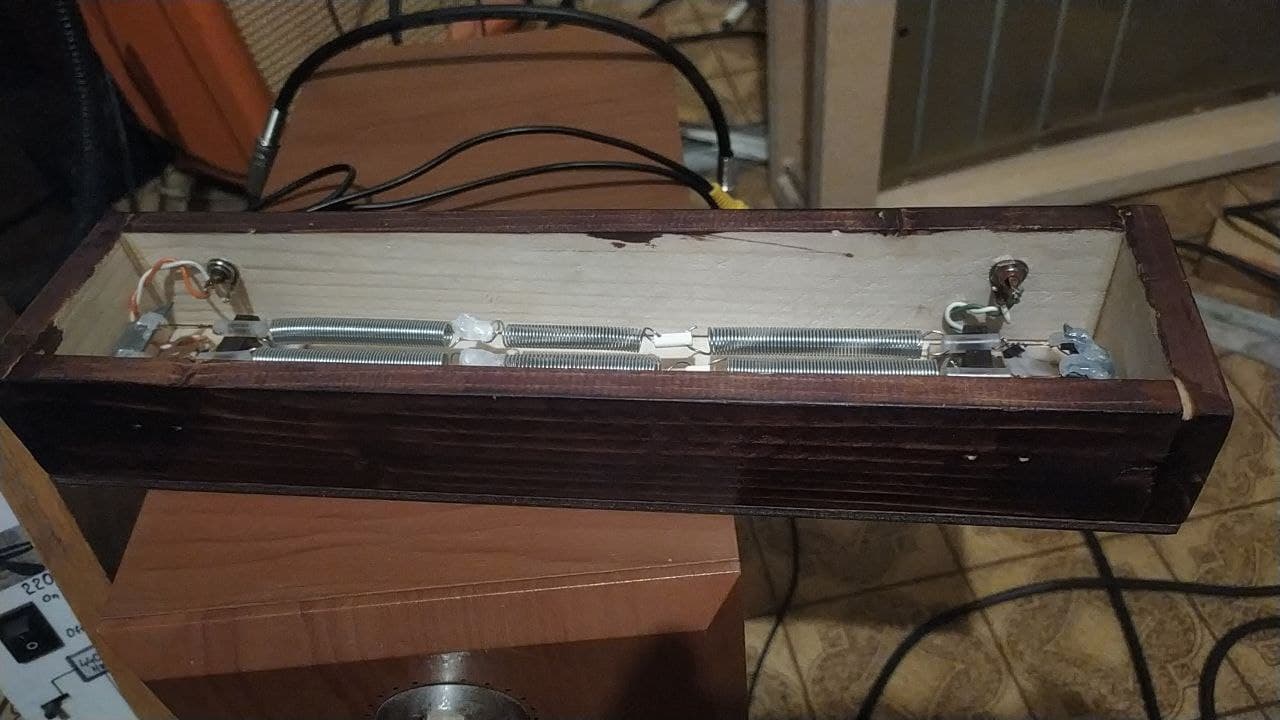
Sorry for sudden jump in quality, i shot this with my DSLR
Now the other part of this build, which I am currently on. It’s not ready. But I wanted to complain. I used parts of this and that schematic, like MFOS + Elliot Sound Products + Skull and Circuits. And unexpectedly I want to complain about Skull and Circuits. So first of all, I am a monkey. I do what monkey do, they see - they repeat. And then they think. So I just collaged the three schematics together, mostly 1st and 3rd one. Elliot’s schematic i used to expand the functionality of a limiter in Skull and Circuits design, which in turn was borrowed from Elliot’s design, so it is logical to go and see what was borrowed and how it actually works. Anyway, one part of Skull and Circuits design, which I liked, was a tone stack on the output. I just redrew it. Now, look, that’s from his schematic
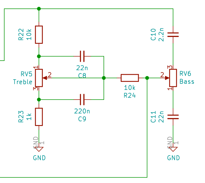
See the problem? That’s not a big issue if you make it like I usually do: on a perfboard and then drag the wires to the pots, but this time I ran out of perfboard space and decided to build the tone section separately, soldered directly to the pots. And while redrawing it in EasyEDA I encountered a problem of… like which lug goes where, which pin is which, and while trying to understand this schematic I felt like I am having a stroke, like: alright, we turn the treble knob and… what happens? Why? And the bass pot, so you turn it and.. What the hell? So I consulted the AI, I roughly summarized the schematic and it kept telling me about treble section capacitors that go here and there, and I was like - wait, it says treble caps are just across the pot. And in typical AI fashion it goes “You are completely right“. I like being right, so I forgave the AI for being dumb (and in reality I was being dumb). But it still didn’t make much sense, so I googled a source on tone stacks and found a great site! Here it is, and you can play with it! And while playing I realized why it felt so wrong when I was thinking about this tone section before, yep. The treble and bass pots on the Skull and Circuits schematic are backwards or… mistyped or whatever. Thing is, dude gaslighted me even without knowing me, that I can respect. I thought I am losing my mind. I even argued with AI about that, while being in cognitive dissonance, but believing in what is written. The moral of this story is - … I guess, there’s no moral in this story, I will continue being a monkey.
Alright, so the faceplate is ready, but I will show it when i finish the soldering and stuff. See you then!
2 Likes
Blahblahblah section:
Well, the reverb module project is still on a pause. And the reason is… Annoying, haha. I just can’t make a PCB for some reason. The heat transfer method fails, because I do like big ground planes, and no matter how wide I make my tracks, they still just don’t want to stick to the copper. I know what the problem is, it’s my toner actually. I bought a cheap cartridge for my printer. And it works for some projects, like with Thomas Henry XR-VCO it did fine. But the more tracks you have, the more possibilities for it to go wrong and you can’t just paint over some tracks, as they are placed in a middle of a track labyrinth. Well, and… eh? What was it… Photosensitive film? Photoresistive film, yeah. This one is just bad. I use russian poor man’s film, it’s quite bad. Copper is fine… I think. it’s toner and film that are bad, sadly
Korone
Anyway, I recently downloaded LTSpice to check something. And it was so much fun, I ended up actually creating a circuit that I named Korone. For legal reasons, it is not a reference. But as it is my debut with actually making a circuit, it is quite a weird thing and not extremely… polished so to speak. Rough, yeah. In that sense it is… similar… Well, anyway
here it is:
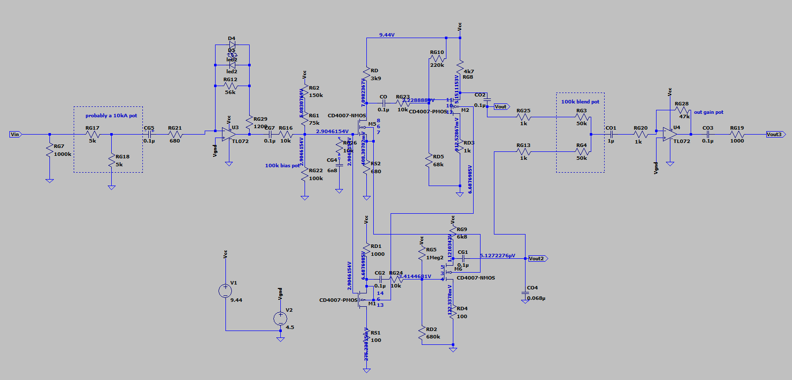
*I took out one of the LEDs from the input stage limiter/clipper, to make the MOSFETs work harder on the unaffected pole.
**CO4 from the Vout2 to the ground was me just putting capacitors everywhere on my actual breadboard.
***It produces quite a lot of analogue hiss, unless you push the volume up high or start playing, so the “idle” noise floor is quite high. The reason to include CO4 was to lower it a bit. It still is hissy, but less now.
****The reason why I avoid active lowpassing/highpassing is… well, it’s too aggressive for a guitar already, and with bass and synth it just sounds bad, in my opinion.
I hope it’s not too compressed. Anyway, V+ here is 9.44v, because I was comparing the numbers with my actual breadboarded circuit. I will redo the gain staging, probably. It is a guitar pedal as of now, but I will make a modular version later, because while playing with it, I discovered that it is an interesting waveshaper. With hot 5v signals and 9.44V headroom on some settings it produces a throat singing effect. I am not kidding. Like full on Sygyt (you can hear the ACTUAL Sygyt here, for example, the whistling high notes). I am not quite sure how easy it is to reproduce though. Cause maybe that was just one of the MOSFETs catching oscillation. That would be embarrassing. Anyway, so formants and waveshaping aside, let me tell you what it actually does as an effect (spoiler: it wasn’t supposed to be an effect)
So roughly the signal flow looks like this:
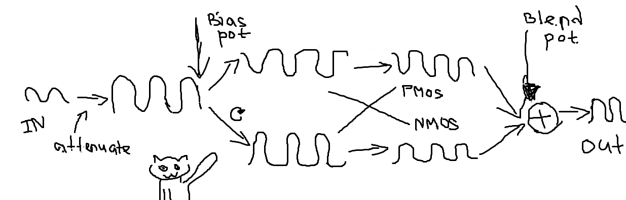
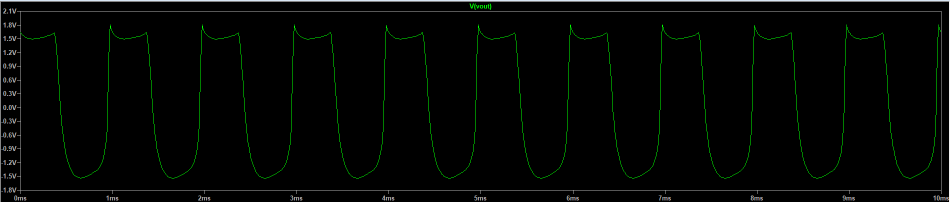
I think it’s self-explanatory, but I will explain some things that are not obvious. the upper row after the split is NMOS1 → PMOS path and the one under it is PMOS1 → NMOS. Both PMOS1 and NMOS1 squish a sine against the nonlinear region and the following NMOS and PMOS are either to make the squishing more pronounced or, when the signal is mostly clean, to just add some class a amp distortion. Blending after that is passive, it averages the signals, on my scope, a real one, the summing looks a lot like crossover distortion. But the opamp output is fine and doesn’t have a crossover knee. I don’t know what’s up with this. Probably some science is happening. With biasing we can move the signal along the curve, so… I think as you push the biasing towards the ground, the output sound becomes more distorted and compressed. While if you lower the resistance to the V+, it makes it louder, less compressed, but also more bassy/mid-lows, as more second harmonic enrichment is happening to the lower guitar strings. Now, with guitar it’s not very throat-singie-ish. There are some harmonics that pop up, but it sounds just like a booster pedal or something. The signal is too low as it is, and if you push it with the input opamp, it just distorts heavily, and the distortion is not nice, it’s very bassy again, muddy. BUT if you just push it and put an overdrive after that - that’s great. It becomes a very rich distortion effect. I wouldn’t compare it to a tube amp, but it’s interesting and it’s not just clipping, you know, it feels more than that. I will rethink the input section though, I think I already mentioned that. One of the things that might be responsible for “whistling” harmonics is a safety mechanism in CD4007. It make the second PMOS “fold” the positive pole when it goes higher than the 14th pin. It quite interesting, actually. I was afraid that it would just burn the chip, but instead it does this. Funny! I’ll show you how it looks in LTSpice. The real scope shows something similar. Not 1-to-1, but similar…
Anyway, the real pain is to rebias it for all the different chips. If you want to build one… I would suggest building it on you breadboard first. Well, actually, I would suggest checking the Vth of your PMOS and NMOS and Kpp or whatever it is, I forgot, and then… yeah… It needs attention. Not a thing that is translatable immediately.
Well, actually it is a mixer strip on steroids. Just a preamp section that I came up with (it was initially with JFETs, then with 2n7000 and then I remembered that I have a bunch of cd4007 chips, so I made a poor decision to use them instead, as they are thermally coupled and well, 6 of them in one chip - that’s great! Not quite…) I think the module version is almost done already, even with this. I would probably have to redo something when raisng the voltage from 9.44v (It works with 9v too, dont; worry! It actually starts working at 7.5v, I think… Maybe i am wrong) to 12v, bigger headroom, less distortion, which is great for a mixer, but not for a waveshaper… In fact… It’s not almost done at all…
CD4007 wasn’t a great choice, because from the ones I have, a bunch of HGSEMI chips, well, almost all of them work great in this circuit. But if you have TI chips and put it there, you would have to redo the whole biasing. Not even just gates, but also drains and sources too (I prefer to call them plates and cathodes, that’s easier to remember for me, which is which). Just for the completion of this report, here’re my CD4007 models in LTSpice.
.MODEL CD4007-NMOS NMOS (LEVEL=1
+ VTO=1.29
+ KP=7.5e-4
+ LAMBDA=0.015
+ CGSO=20p
+ CGDO=20p
+ GAMMA=0.6
+ PHI=0.65
+ TOX=1e-7
+ CJ=2e-4
+ MJ=0.5
+ PB=0.9
+ CJSW=5e-10
+ MJSW=0.33
+ JS=5e-9)

.MODEL CD4007-PMOS PMOS (LEVEL=1
+ VTO=-0.72
+ KP=5.2e-4
+ LAMBDA=0.02
+ CGSO=20p
+ CGDO=20p
+ GAMMA=0.6
+ PHI=0.65
+ TOX=1e-7
+ CJ=2e-4
+ MJ=0.5
+ PB=0.9
+ CJSW=5e-10
+ MJSW=0.33
+ JS=5e-9)
Most of the number I just stole from another model and VTO, KP, LAMBDA and csgo or whatever the hell, Chatgpt computed for me based on my measurements. It does well with analyzing the data. I had to tweak PMOS KP a bit, not that I know what I am doing. I just notices that with the same gate voltage there is a big difference between real breadboarded circuit and a simulated one, and VTO I am positive that it is around -0.7v, I measured it many times. So the only other thing that I understand is Kp that in russian, I think is “крутизна характеристики”, I think. So I kinda understand what it is and what it does, i felt that I can tweak it. And after tweaking it actually started to show the numbers that are extremely close to the real PMOS. With NMOS… I wasn’t as ready to mess around, but it is somewhat similar too.
Anyway, maybe I will write a report after making a module version of this thing. Or maybe not! Who knows?