Is there a module that can help reduce transients/clicks? This is for changing samples in mid-play, which can introduced step changes in audio signal. I’ve tried using filters and envelopes/vcas but can’t really get good result. I’m thinking of an algo that targets obvious discontinuities in signal rather than e.g. filtering out high frequencies.
If I were writing one, I think I’d make it watch for discontinuities, then modify the next N samples so they join up more smoothly, perhaps in first derivate too. I bet someone has done this!
The general answer is “a slew limiter controlling a VCA”. In some of the older samplers I think it’s hard to get rid of, the newer samplers are probably better where that’s concerned.
Is there a module that will detect a zero crossing point in a sample? Use it twice — once to mute the first sample, then a delay while it waits for a zero-crossing in the new sample before it switches to it.
Oh, wait, maybe a comparator or two will do it, and maybe one or two slope detectors so that if the first sample is going down when it crosses zero, the next sample is also headed down after it crosses zero.
It’s the kind of thing that’s really easy to do
[Edit a few days later - oops. I posted before I finished writing. I was going to make a reference to the way the Audacity audio editor can tweak selections by locating zero-crossing points and adjusting the selection start and finish.]
I should think a simple crossfade would handle things nicely, assuming you can isolate the two samples to separate inputs.
Granted it is a lot easier when the module doing the switching has the crossfade built in. I am pretty sure the de-click option in the VCV 4->1 and 1->4 sequential switches uses an internal crossfade. I know that is how I implemented de-click with my Venom Bernoulli Switch.
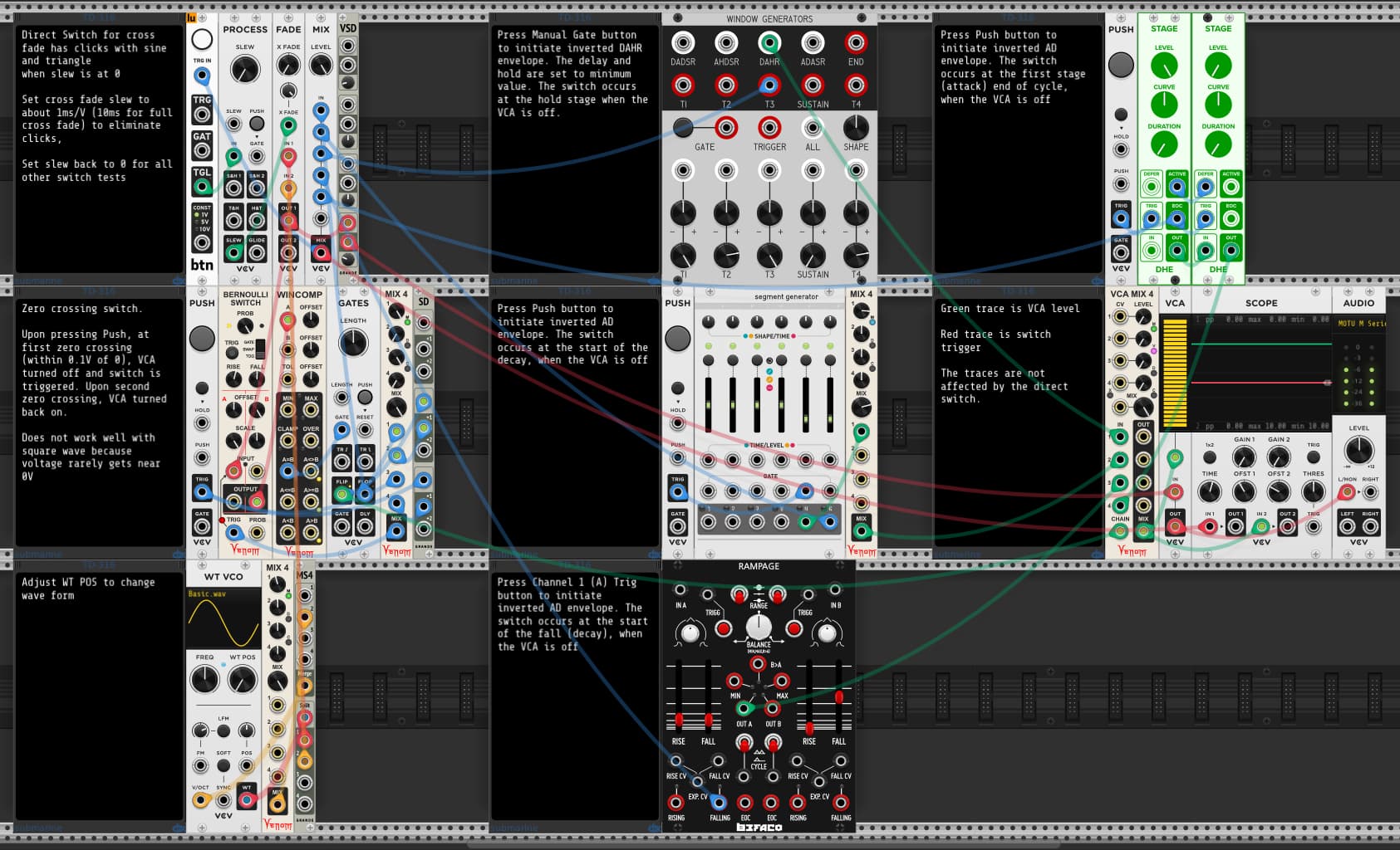
For this demo I use the VCV FADE module as a switch - 0V at the X-FADE input selects IN 1, and 10V selects IN 2. As long as the X-Fade input is not slewed, then the switch is instantaneous, and you can hear the pop or click. Set the PROCESS SLEW rate to ~1ms/V and the pops disappear.
For all the other tests, make sure the Slew is at 0. All the other tests use a common VCA to temporarily mute the signal before sending a trigger to toggle the FADE switch.
Using the idea from @john_rose kind of works - mute between two zero crossing points and switch while muted - works OK, though not great, and it is not reliable. For example, square waves may rarely approach zero, causing switch timing to be unreliable. It is also fairly complex to implement.
But the Lars suggestion is simple to implement, and works extremely well. All you need is a function generator that can produce an Attack Decay envelope with a gate or trigger that fires at the end of the attack phase (or start of the decay). The envelope must be inverted so that it mutes the VCA rather than turns it on. In this demo I show 4 different possibilities.
Intuitively I’d say that a gradual rate of transition at the start of the transition is more revelant then at the end (exponential increase/decrease).
Seems trivial, might be inaudible in practice. But for the suggested 1 millisecond transition time we’re still modulating as many samples as we have samplerate in kHz (eg. 44, 48, 96, 192…). So there’s some room to implement a specific modulation curve.
The slew rate unit is ms/V, not ms. So for the crossfade CV to go from 0 to 10 (or 10 to 0) at 1ms/V it takes 10ms, not 1 ms.
Regarding curve shape, I agree exponential may be an improvement. But unless I am misunderstanding what you are saying, I disagree with some of your statement. The end of transition is equally important as the beginning when switching between two signals. I’m assuming we both know that our perception of loudness is logarithmic relative to sound power, not linear. To compensate we want an exponential power curve to get a linear perceived loudness ramp, regardless whether going from low to high or high to low.
So for the sound fading out, the power can drop quickly at the beginning when power is high, and slowly at the end when power is low. Conversely for the sound fading in, it can rise slowly at the beginning when power is low, and quickly at the end when power is high. I chose to use a linear power curve instead. I imagine if I switched to an exponential curve I could get away with a shorter overall fade transition. But I am very happy with the results of the linear curve with a 10ms overall transition time, and to keep things simple I chose to stay with linear. I don’t hear any pops, nor do I perceive any gap or spike in sound level.
Bit of an aside, but wavesplicing has been done in hardware:
I have this module, though I have not used it in anger for a good while and would have to refresh my knowledge. It does not work with a digital switch (as I learned), which is too slow at audio rates, but only with an analog one.
I believe the Mok Waverazor VST can also do wave splicing.
Yeah - zero crossing works perfectly well in an analog world - it has to actually cross zero, no matter how steep (until we get to quantum scale anyway).
But in the digital world voltage can jump directly from -5V to +5V, without ever getting close to 0. So zero crossing solutions do not work so well. We can certainly detect that zero has been crossed. But we may not be able to activate a switch when the voltage is actually at (or near) 0.
Yup. My bad. Speed is always something relative to time. Not just time. That’s just duration. I interpreted the1 ms time as the total duration of the transition. Doesn’t matter much for the reasoning I guess. Just more time and more samples that represent the transition.
I did ponder on that. And you might be right. My train of thought was based on your extreme example of the square. Transitioning from full positive to full negative. My intuition said that coming from a stable voltage, a sudden steep drop might might be perceived as a discontinuity (pop), while the end rise (or fall) would end in a stabe state (either full positive or full negative for a half a cycle time). But with either exp or log we’d get a sharp sudden angling at eithe start or end.
Linear interpolation would even that out over both ends of the transition.
Maybe go for a tanh like curve to have a more gradual transition at bot start and end of the transition…
Well, it’s all about the goal (effectiveness), which is preferably achieved by means at the lowest cost (efficiency). Generally, good enough is good enough (goal achieved at acceptable cost). And linear seems to be a good enough solution.