Blippoo Box by Rob Hordijk

I have made a patch emulating the legendary Blippoo Box by Rob Hordijk. You can find a link below. It uses some paid modules, so it is not entirely free. You can check the list of used modules below as well in a separate txt file. Maybe you can replace most of them, if you want a completely free version. Most of the paid modules are in the Post FX chain, so you can leave this out as well.

A lot of info on how the box is made is in this article:

Hordijk Rob (2009) The Blippoo Box - A Chaotic Electronic Music Instrument, Bent by Design.pdf (2.5 MB)

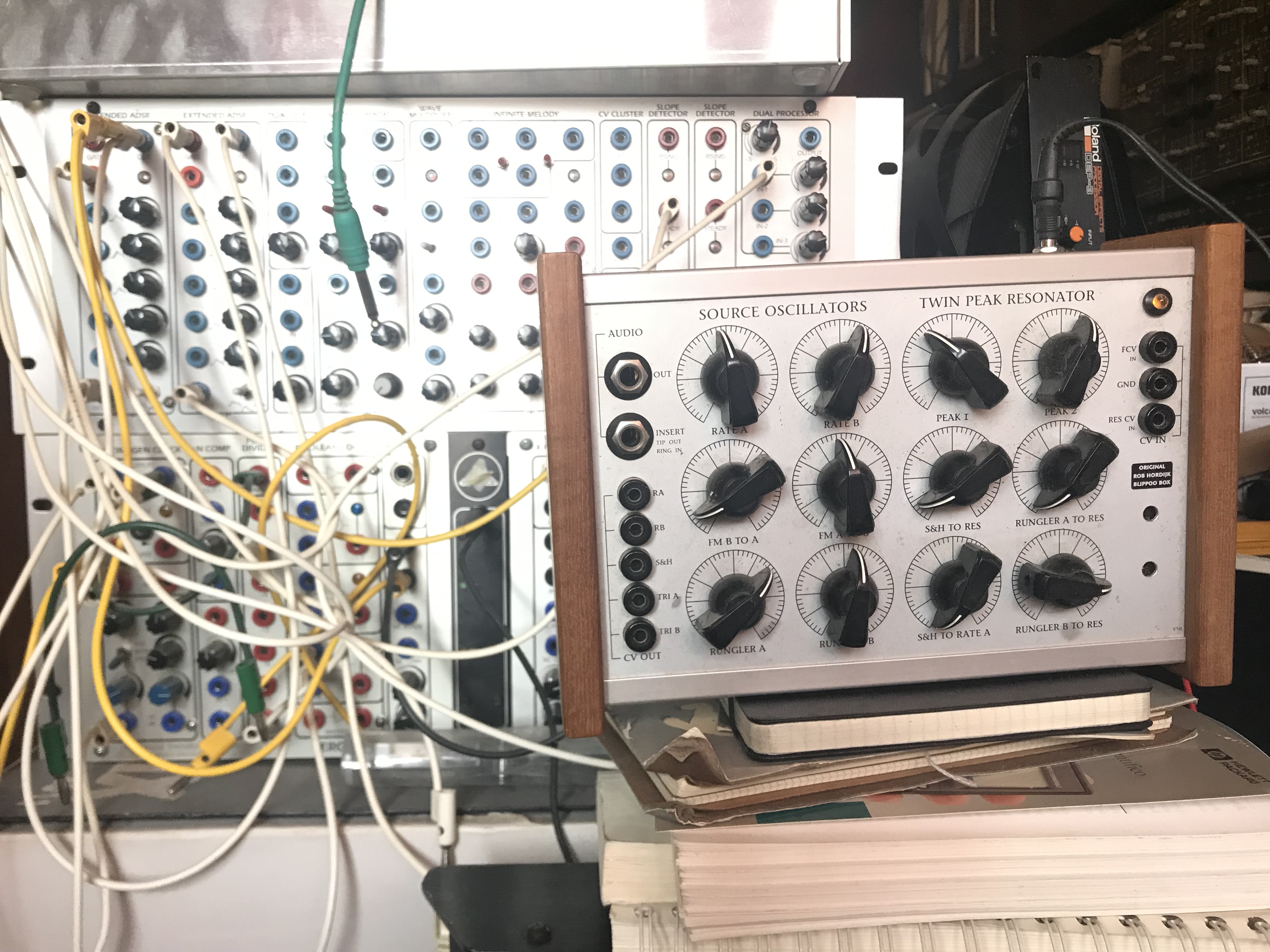
I would love to have a hardware version… but they are very rare, so I settled on this emulation.

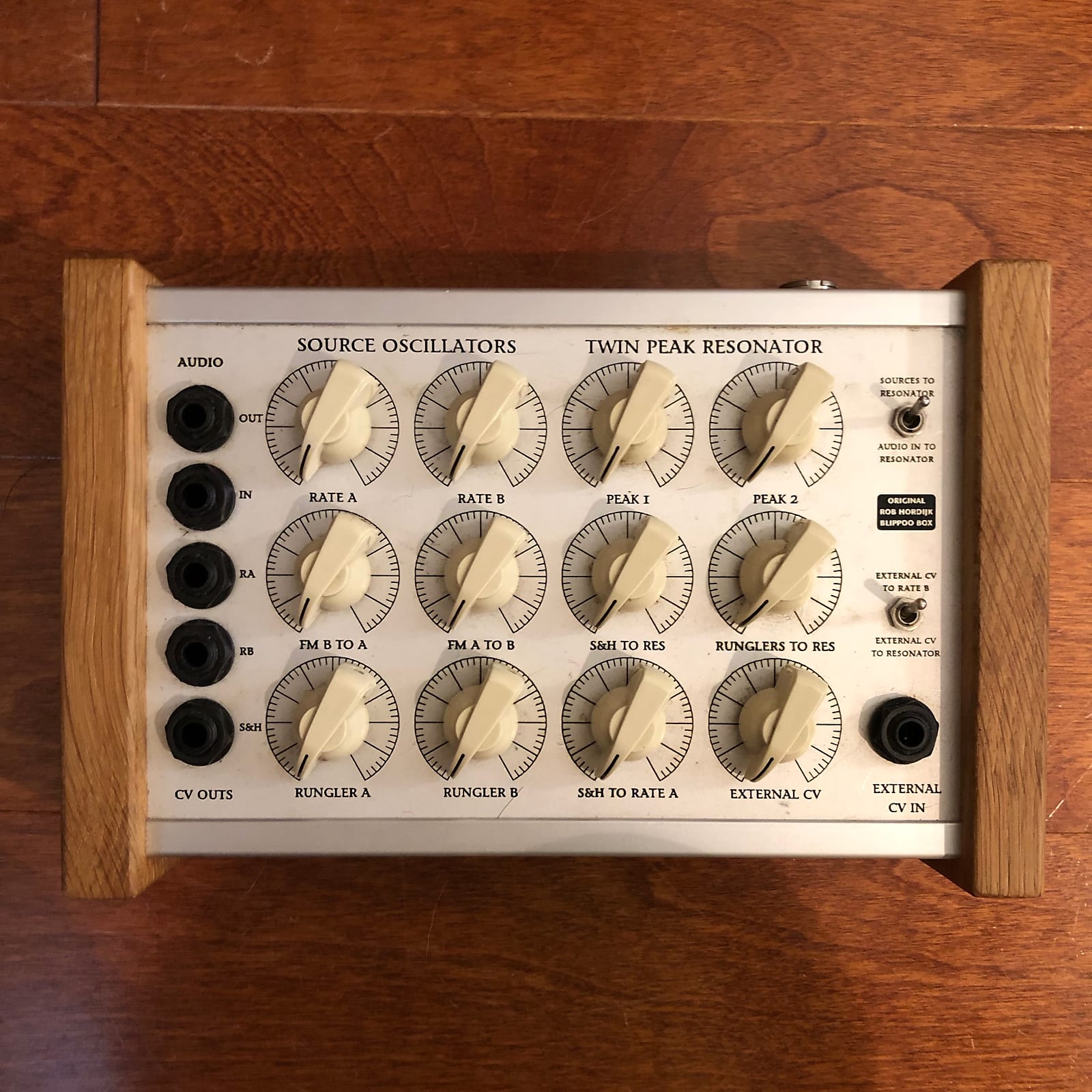
The Blippoo Box is the big brother of the Benjolin: It has also a chaotic 2 oscillator core but has two runglers and a sample and hold function, making it very different in behaviour then the Benjolin (only one rungler and no sample and hold) The runglers of the Blippoo Box are also different: 2x4 bit shift registers that are cross-patched and no XOR. The S&H is clocked by the PWM signal, that also triggers/pings the resonator. The PWM signal creates a trigger whenever osc A and B have the same value. The S&H holds this value on each trigger OR it samples a mix of the two runglers. In the original version of 2018, you could choose the source by a switch, but I have implemented a crossfader in between the two sources, so you will have a much more flexible source.

Also the filter/resonator section of the Blippoo Box is very different from the Benjolin. The Twinpeak Resonator are two parallel lowpass filters, that are subtracted from each other. This creates a very versatile bandpass filter, with variable bandwidth and two resonant peaks on the borders of the bandwidth. In the original Blippoo Box these are 2 18dB/oct lowpass filters. I have chosen for two LP4+ filters by Slime Child. They sound great and I like the steeper slope of the 4 pole filter. Also the resonances/Q’s of the filters are very controllable. I have implemented an all-harmonic distortion into the resonator as well, by feeding back the BP2 output into the FM of the cutoff frequencies. This slightly tilts the resonant output as described in the mentioned article. I added a control for this distortion (colour) as well, so you can dial in from no distortion, to a subtle character.

The input into the resonator is controlled by a crossfader as well. When nothing is patched into the EXT input, this control works as a volume control of the normalized PWM input.

In the emulation I have also added a small noise source, to emulate a bit the slight instabilities that are present in analog electronic circuitry. The chaotic core makes it hard to detect, but it definitely makes a difference, or I believe it does :sweat_smile:

In the patch is a POST FX chain, adding an amount of reverb/room to the signal. I used the Valhalla Room VST and VULT Jorus for this. Both are paid modules, but you can omit them or replace them with another module. The post fx is applied to the upper frequency spectrum, controlled by LaLa, so the low end of the patch is untouched by the effect. You can control this with the CROSSOVER knob. Also, the effect is side chained by the dry signal, preserving the presence of the Blippoo Box.

There is also a randomize button: this randomizes the knobs, but not always, creating a new variation of the previous setting, instead of a totally new one. I believe it is more musical then just a full on randomizer. If you connect a midi controller to the patch, you have to turn off the randomizer section: You can only map one signal to a parameter.

I hope you enjoy the patch! It is quit deep in possible sounds it generates: from sparse percussive sounds to harsh noise, from drones to weird melodic chaos. Because of this, I did not (yet) record a demo video of it. I will try to record some settings though, to give people some easy access demo sounds.

Feel free to share your outcome of course!

Here is the list of modules used: BLIPPOO BOX_ROB HORDIJK.txt (2.0 KB)

Here is the patch: BLIPPOO BOX_ROB HORDIJK.vcv (16.9 KB)

6 Likes

Immensely fun to play with. Awesome job on patching this up!

1 Like

I have made a quick video of the patch, scrolling through some random settings. Sometimes the results can sound quite abrupt and/or harsh, so be warned :innocent:

It is by no means a composition, just for quickly demoing some sounds it is capable of. Enjoy!

EDIT: I accidentally uploaded a video with multitrack audio instead of stereo. I removed the video. Fixing it now, and I will upload a better version with true stereo instead of mostly left channel soon. Sorry for this!

3 Likes

Very excited to try this, but couldn’t get it to work. I do not have oppressor pro and couldn’t work out how to fix the signal flow. Any help greatly appreciated, as I love the blippo sound.

here is he improved video link:

1 Like

Hi,

what you could do, is replace the Oppressor Pro with 2 instances of Oppressor. Then connect all left channel cables to no.1 and all the right channel cables to no. 2. So instead of one stereo module, you will have 2 mono modules -which is in effect the same. Oppressor is free I believe…

Hope this helps! If not, I can try and make a patch without the oppressor.

Here is a pacth file with the 2 instances of Oppressor (free): BLIPPOO BOX_ROB HORDIJK_2.vcv (17.6 KB)

3 Likes

Amazing. Thank you very much. This is fantastic.

1 Like

Great patch - tremendous fun! I was able to find some beautifully dynamic formants.

I see you have taken the philosophy of the Benjolin V2 vs V1, providing more input and output patch points and control knobs than the original for all the signals within the Blippoo.

For the twin peaks, did you try using the LP2 as FM feedback instead of BP, as is described in the Rob’s paper? I swapped the FM source, and actually prefer the LP2 feedback.

Slime Child SubStation is not free, although it is open source, so you can compile your own (without the Slime Child graphics).

If you are willing to use low pass instead of band pass for the feedback, then the Vult Lateralus is an excellent free alternative for the twin peaks filters. It offers 1, 2, 3, and 4 pole outputs. I swapped them into your patch and tried using 4P with 2P feedback, as well as 3P with 2P feedback. I preferred the latter. I think it would be worth trying 4P with 3P feedback, as well as 3P with 1P feedback.

I figured out the function for most of your control knobs. But I haven’t traced the S&H > SPRD PK knob, so I’m not sure what it does. I’m guessing it applies the S&H output to the two filter cutoffs, positive for one, and inverted for the other. Is that correct?

You have inspired me to take a stab at creating my own Blippoo patch. I think I will try to replicate the controls (and constraints) of the original Blippoo first.

Rob’s writeup is a great resource, but it is also very frustrating. I’m pretty sure there are significant inconsistencies.

The text talks about the S&H receiving two triangle signals, and having a comparator fire a pulse when they are equal. The pulse is used as input to the twin peaks, and also triggers the S&H to sample the triangle voltage. So the text describes only two inputs for the S&H, both triangles. It looks as though this is how you implemented the S&H, though you trigger when one signal is greater than the other.

The diagram shows a comparator receiving two triangle inputs, and it is totally isolated from the S&H. The diagram sends the comparator output to the twin peaks. The diagram S&H has three inputs, two square, and one triangle. My guess is the square inputs are ANDed, and when that is high it triggers the S&H to sample the triangle input. Not sure if it triggers on rising edge only, or both rising and falling edges.

I suppose the diagram is a refinement of the text, or vice versa. But I haven’t a clue which is the final design that was used in production. Or maybe he started producing one, and then switched to the other at a later date. For a digital Blippoo I suppose the diagram version is easier to implement. I imagine a digital comparator could miss when a pair of triangle waves are equal, even with a tolerance built in. Conversely the AND of two square waves would be reliable, but highly correlated with the Rungler transistions. Since the square waves also clock the Runglers, the rising edge of the AND of the square waves will always coincide with the clock of one of the Runglers. The same for the falling edge.

3 Likes

Thank you for your reply and helping me sharpening my experiments.

3 versions of controls

There are three different versions of the Blippoo Box actually. In all versions Rob maintained the same format of 3 rows with four knobs.

  1. The Original: with an implemented cross FM in the controls, an external CV that can be routed to oscillator B or the filter input, and a S&H to only oscillator A, a S&H to both peaks of the Twinpeak resonator, one control of Rungler mix to the Twinpeak and an attenuator for the external CV input. This is the version the article talks about.
  2. An in between version (I forgot the year now, sorry) where there is an optical sensor also implemented, creating a very versatile gesture-controlled modulator. Also the CV input is gone and replaced by two controls of Rungler signals to the filters, instead of one. The S&H is the same as in the original version.
  3. From 2018 on, the optical sensor is gone and also the FM controls to the oscillators. When you want to do the cross FM, you need to use the patch bay (and an external mixer) But the S&H is extended with an extra source (the Rungler mix. Also the S&H modulates the peaks of the filter differently: the Rungler mix is inverted on one of the peaks, creating a spreading of the two peaks in opposite directions (they can overlap or swap or I don’t know how to put it in English -not my native language) With the triangle wave as source you still have the sweeping quality, but with the rungler mix as source, it creates a nice extra stepped CV.

I deviated from this at a certain point. It was a really nice limitation to start patching: only 12 knobs and maybe 1 or 2 switches. But in the end -because software does not have a space problem/challenge, I chose to extend. For instance to have attenuators on all the CV inputs. Just handy.

S&H

Yeah, the sample and hold was/is on of the biggest challenges of the patch. I interpret it as the comparator output of the two triangles, triggering when both are equal. But I stumbled upon a lot of trouble when doing this with the comparators in VCV, especially at high audio rates. Some of the modules couldn’t go that high and some were not able to detect all. So in this version I opted for the comparison A>B comparison. The rising and falling edges are (almost) the same as the A=B triggers. What I eventually did is using the Fundamental GATES module to trigger the rising and falling edges of the PWM signal. These two pulse trains I combined with an OR logic. This combined triggers I use as a clock for the S&H module. The source that is sampled can be either of the triangle waves. It doesn’t matter which, because the CV value is the same when compared. Of course in my implementation this is not really true, because of my workaround. Using the AND function on the pulse/square waves is different. They will indeed coincide with the clock of one of the Runglers. But with a comparison of the (FM-ed) triangle waves you will get different triggers, that do not coincide. I believe this is the better option, as they attribute more to the whole chaotic core this way. But I will investigate the diagram more, you are right there is one pulse wave involved. But maybe this is a mistake in the diagram??? I hardly dare to say this lol

Filters

The filters are still an ongoing discovery for me. I have tried a lot of filters and occasionally swap them in the patch when I want a different flavour. The Vult ones are great, as is the Liquid filter of Audible Instruments, the filter of Nano Modules etc etc. They do not react the same though when applying an FM feedback. Some will distort in a different wave shape as described in the article. Which is fine, if it sounds good! And as said before, I change filters quit often in the patch. The LP4 sounds really good though (this whole collection is amazing -I forgot it was not free, it would be an instant buy again for me)

Diagram

Sorry for the long read… haha I get really carried away with finding the right nuances in complex patches as these. You really learn a lot when trying to emulate such thought out instruments as this one. Anyway, what a way to spend hours trying to explore this :smiley: Your WinComp module for sure helps tremendously with it, so a big thanks for creating this module. (Also the fundamental collection is very powerful when you go into extreme audio rates. A lot of S&H modules kind of freeze above a certain frequency. I do not know why, so my journey has not ended yet!)

I am all for another attempt, so I can learn from a different view etc. , so go for it! My Blippoo patch was ready to share, so it maybe can evolve into something… I don’t know… I am not a designer alas, just a musician! :wink:

2 Likes

Do you have any links to descriptions, or photos, or … to the 2nd and 3rd Blippoo versions? I would love to read about them.

I started patching the components to the Blippoo, and I also used my Wincomp for the S&H comparator. I opted to use equal, but I set the tolerance to +/- 0.5 volts so that I don’t miss any crossovers. It also gives the PWM pulses some width (using Benjolin terminology). I can see how triggering on the leading and trailing edge of the greater than gate should give virtually the same S&H result. But I believe you use the greater gate comparator output directly to feed the filters, so your PWM signal is generally one octave below my equal gate version.

Regarding S&H, I’m having good luck with the Bogaudio S&H. It actually is doing better than the VCV Process module with my equal gate triggers. The VCV module handles high frequency pulse triggers perfectly. But the Wincomp oversampling changes the shape of the pulses such that Process no longer recognizes some of them, and triggers get dropped. But the Bogaudio S&H does just fine with the oversampled gates.

There certainly are a lot of choices to be made / experiments to run!

EDIT - I need to do more tests. Now I see that the Bogaudio S&H is detecting false triggers with the oversampled gates at high rates.

I have a DC filter of 5 Hz on the input of the filter, changing the PWM from square wave to positive and negative “spikes”. The TP filter also reacts to negative spikes, so going suddenly from say 0V to -5V pings the filter as well.

One squarewave phase thus results in 2 triggers; it is the same octave in frequency as the equal triggers I believe? I could be wrong…

In this way the width of the triggers (or downslope of the spikes) also changes, creating more variation/colour of the sound.

But I will try your setup with the wincomp and listen to it!

I will post some pictures of different versions later.

1 Like

These are the pictures of the different versions:

V1

V2

V3

It shows that there is no static design of the instrument, which I like.

I found snippets of information on the different versions in forums etc. There is not really one central point alas. Also watching and listening to this video of Rob Hordijk explaining and playing with the V3 Blippoo was very informative. Around 3’00" he explaines the S&H as well.

Hope this helps!

1 Like

mine

8 Likes

One day… maybe… I will have one…

We need knobs like that in VCV Rack

https://www.cosmocorp.com/en/kp-handler.cfm?CAT=S&SUBCAT=1&KN=1&src=17

I’m not sure this is the right knob, but they’re very similar.

These are usually called “chicken head” knobs. Pretty common on guitar amplifiers and audio processors the want to look “vintage”.

1 Like

Here’s one svg I made ,

ChickenHead47x47Clean2

now what ? :sunglasses: :blush:

2 Likes

$$$$$

( now I need to write a “complete sentence” to make this forum software happy)

1 Like

That’s what I knew them as (Chicken head knobs). Cosmo has been in the market since 1945 - they call them “military pointer knobs”.

1 Like