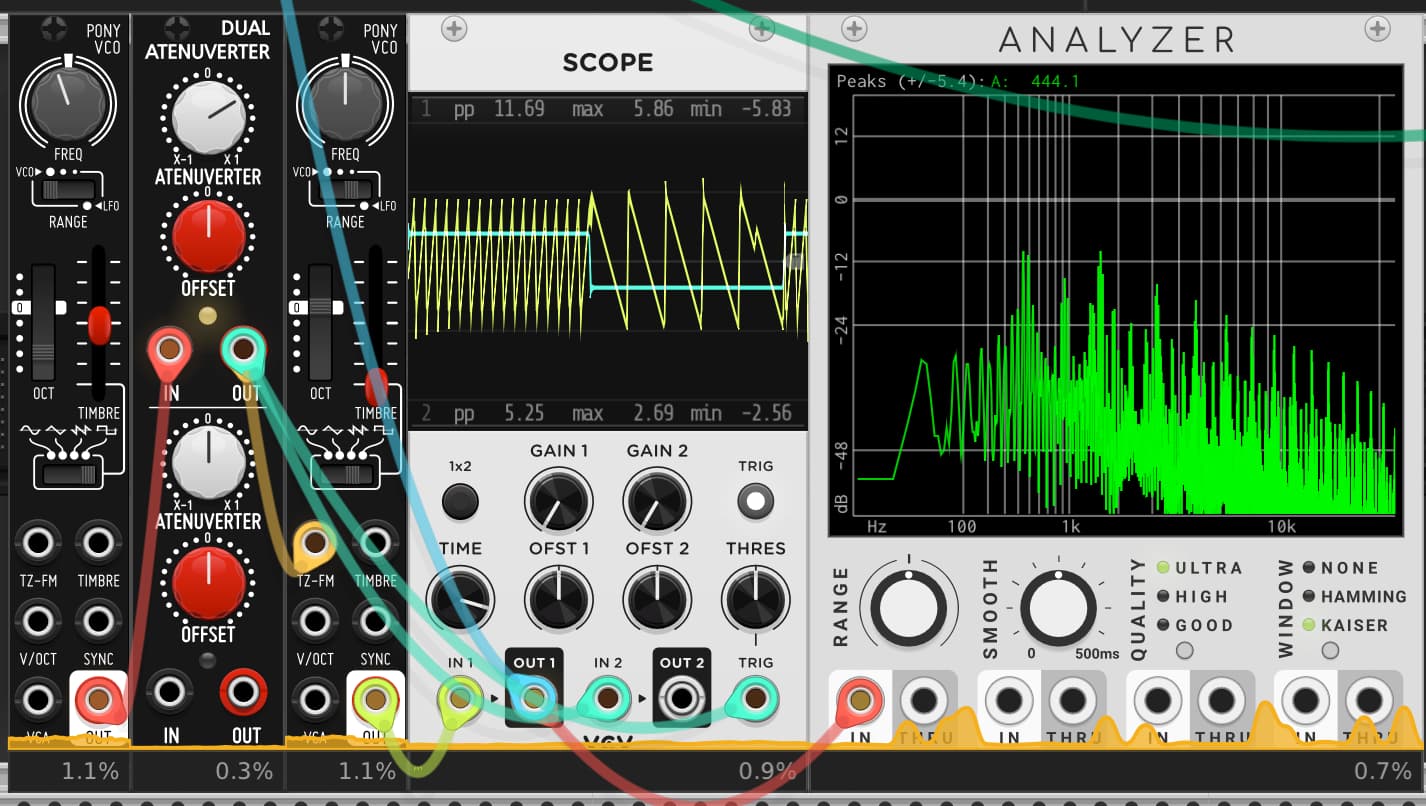
“Clearly, the aliasing artifacts are significantly more supressed than with no anti-aliasing, however they are still of significant magnitude. One option would be to use first-order ADAA in tandem with a modest amount of oversampling, maybe 2x:”
Is this more or less the same as applying a one pole lowpass filter before they non-linearity?
Oh and in surge proper we run at 2x in the entire pre-fx pipeline. The modules have a slightly different strategy because they are modules and right now the waveshaper and filter only have a zero latency 1x mode (but i might add an 8 block latency oversample mode as we go as an option in both)
For most pitches I’m doing exactly what “WT VCO” using pre-calculated tables. Only difference is that I have more tables. For Oscillators, we have the luxury to just not create the aliasing in the first place. For effects it’s a bit trickier…
If the wave-folding is a part of the osc. you can view it as a wave-table-oscillator where you generate the waves and filter one cycle using FFT just in time as parameters change… but as you imagine it can become complicated very fast.
I would oversample it and use band-limiting, I’d also use minBLEP or table-based oscillators to minimize the aliasing without use of the wavefolder, and to reduce aliasing produced from FM.
I’d also use what I like to call an “anti-aliasing detrebler” which I use in PureData to reduce aliasing. It involves a very gentle hi-shelf that pulls off some higher frequencies past around 15k, alongside a few splayed shelves and LPFs of varying magnitude (I generally used a steeper hi-shelf at 15k, a 1-pole lowpass at 18.5k, a 2-pole at 19k, and a 4-pole at 19.5k, all non-resonant.)
It helps to reduce some of the grosser hi-end produced by digital synthesis and cuts back on the amount of aliasing. I don’t know how well it would work here, but it’s been my go-to add-on method to reduce waveform aliasing in PureData.
Some interesting ideas in this thread, thanks all! @baconpaul I took a look at ADAA, very appealing idea. I got it working for the first folding stage, but there are actually two in series. As ADAA introduces “memory” through filtering, I don’t know if doing this multiple times causes issues? I need to think about it a bit…
So if you look at the surge folder code you can see we have a couple of folders and a generalized ADAA for a set of linear connected segments. This is (following a paper cited in the code) how we do the buchla style multi-folder. I wonder if your “two in series” can actually be a “one more complicated”. Of of course you can have two state registers also. That would work fine.
Thanks for the info, I don’t know how I slept on Surge for Rack for so long, it’s awesome!
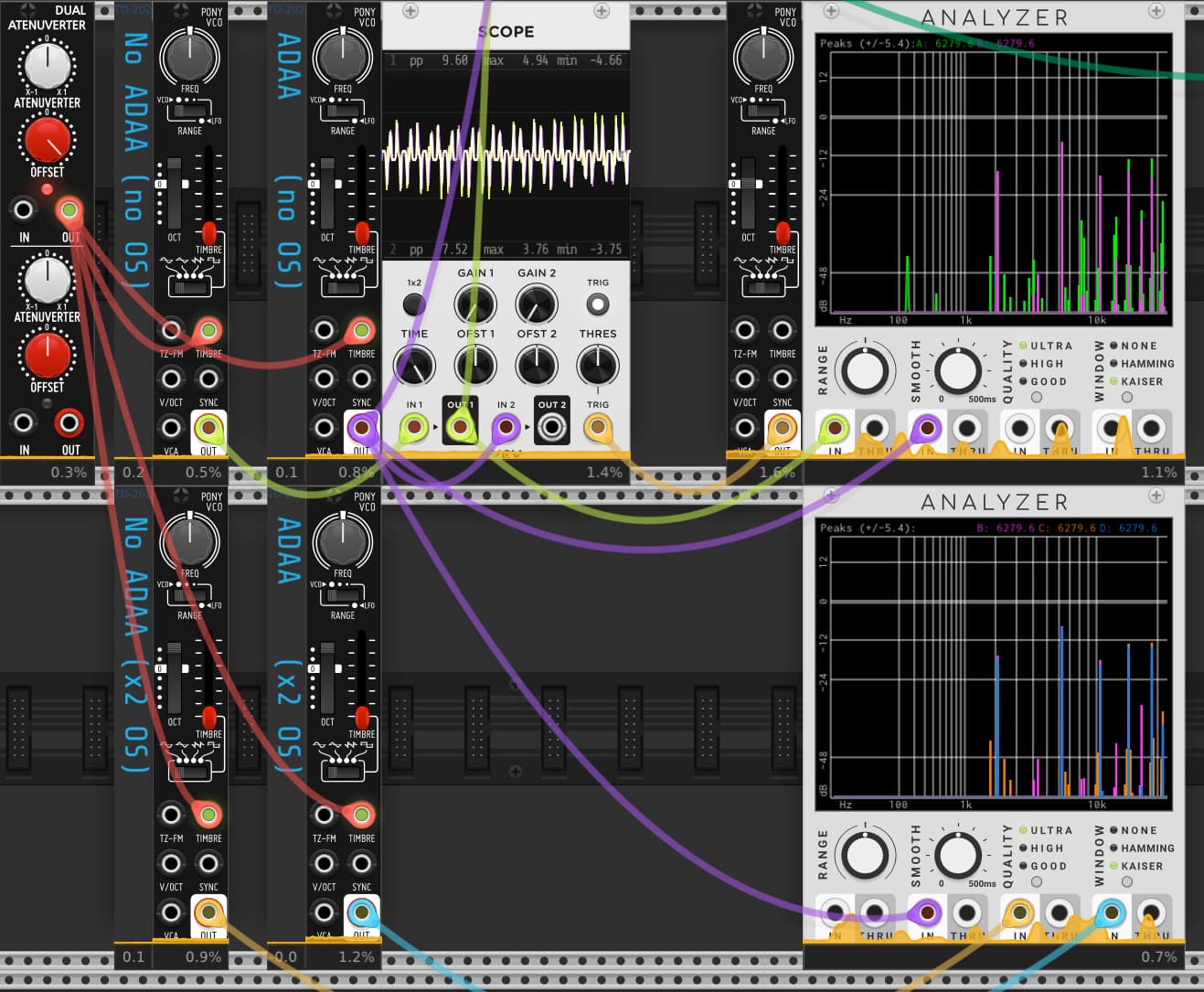
I’ve implemented it as two ADAA stages (I can’t work out how to do a single one due to the slightly odd way the folder works). Some results with a 2k sine being folded
No ADAA, No OS - 0.5% CPU, lots of aliasing (green trace)
ADAA, No OS - 0.8% CPU, reduced aliasing (pink trace)
No ADAA, x2 OS - 0.9% CPU, some reduced aliasing, but a few bands left (orange trace)
ADAA, x2 OS - 1.2% CPU, very little aliasing at all (blue trace)
So for lower oversampling rates it definitely looks beneficial. Once you get up to x4 OS though (not shown) it’s diminishing returns.
Yeah 4x oversampling is a nice big hammer. But you can think of it all just as filters right? The adaa is a particular form of filter on the integral of the transform and the 4x oversampling is an explicit filter up and down.
Adaa is super nice on waveform generation also - it’s how the modern oscillator in surge instrument and the new surge modules (not yet done and not yet in library) work and it just sounds really good. A useful technique
That looks good, thanks for the reference (here for the lazy). Before I invest time into learning about / implementing this, do you briefly have any expectation if the method will naturally account for waveform reversal (i.e. saw → ramp can happen for big enough TZFM). Whilst I’m still getting my head around it, it feels as though the filtering effect of the second order time derivative should still work.
If I understand the sync response (here), it sounds like “let the derivatives handle it” works and would be the same sort of idea?
The sync is a bit of a mess. I have a better way worked up. Basically the sync doesn’t take into account the pre-turnover phase as implemented so averages two things and can alias at high sync. The correct way is to calculate the antiderivative with the sync clock but that algebra is ugly in a couple of the cases so there’s that averaging hack there.
I don’t think you need to implement it though unless you want to! We have it in the new surge modules which should be in the library this year and you can grab them from our GitHub now to hear the oscillator.
My mistake, again my experience is only stemming from PureData (keyscaled output filters for band-limiting would be used with BLEP oscillators sometimes.)
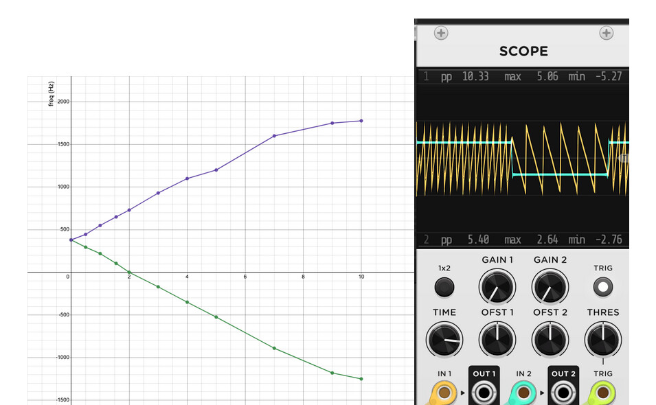
Some details on the TZFM behaviour of Pony if people are interested.
Here I’ve set (hardware) Pony to default (sin, octave zero, centred freq knob, ~400Hz) and slowly increased the amplitude of a 50% duty square wave (40Hz) modulating TZFM up to a max of 10Vpp. I’ve measured from a spectrum analyser the rough location of the two peaks. Where the frequency is reported as “negative” on the graph below, I’ve switched to saw and verified that the direction has changed during the negative part of the modulation signal (i.e. from saw to ramp). The “through zero point” occurs when the negative (minimum) part of the modulation signal is around -1V (2Vpp). Here if you are accurate, you can even get the oscillator to stall so you can get some nice gating/formant like tones. The TZFM input is AC coupled which makes sense for pitch stability, but can be confusing when trying to interpret the behaviour (say for non-50% duty cycles of the modulating signal). This will be optional on the software version.
Also perhaps unusual is that the thru-zero point (-1V) is independent of carrier frequency, which is different to WT VCO at least (I think!).
To clarify the above plot is from the hardware analogue VCO (datasheet), but the software emulation (which i’m currently developing) will be FM not PM as you say if I’ve done my job correctly…