Any module like Doepfer A-152?

Hi, I was looking through the Library for a switch or router with a function similar to the Doepfer A-152.

I tried a few, including Bogaudio ADDR and Befaco Muxslicer, but neither passes through the input signal.

I tried a window comparator + Count Modula Carousel, and that didn’t work either. I couldn’t get the outputs in the correct order, probably because I’m missing some basic concept.

I’d like to take a sequencer cv out, split it, say, in octaves, and send each split to a different quantizer+oscillator.

With the A-152, the trick is to use the sequencer cv both as address cv and input cv.

Ideas?

EDIT: I’m a dummy. Was going to suggest Dumbwaiter, but realized this was the opposite of what you needed.

Perhaps the Count Modula Switch 1-8 or 1-16 would do the trick with “direction” set to voltage addressed, though as I recall, you also need to hook up a clock or gate input, even if you’re using the addressed mode (it doesn’t just scan freely when you change the address).

2 Likes

nysthi::thecage

the squonk too

4 Likes

It is absolutely incredible that there is a NYSTHI module for everything. :mage:

8 Likes

Great suggestions! Thank you guys.

I gave a first try with Count Modula Switch 1-8, and although is kind of working, it has a strange behavior. I am feeding it the output of Grayscale Permutation, which goes between 0V and 8V. I selected only 2 outputs for the switch, and I would have expected a fairly even distribution of signals between output #1 and #2. Instead it seem to favor output #1.

If I set the output of Permutation between 0v and 5v, for instance, then the signal never goes to output #2.

I gave a quick test to TheCage, and I do not think it does what I need, or I still need to get a higher education degree, to understand how to use it the way I’d like to. :grin:

What am I doing wrong?

I haven’t used CM Switch in a while but I remembered that CM has exceptionally good documentation!

The manual (p. 96) says that in VA mode “[t]he addressing voltage is scaled such that 10 volts always equals the last step regardless of the selected length.” I assume that in length-2 mode, 0v to 5v present at ADDR would switch to 1 on each clock pulse, and 5v to 10v would switch to 2 on each clock pulse. That’s consistent with your observation that 0-5v doesn’t switch to 2, and if Permutation is doing 0-8V, you’d expect to see output 1 more than output 2 (about 2/3rds more often if the voltages are uniformly distributed).

If that’s a correct diagnosis, the simplest solution would be to linearly scale Permutation’s output to 0-10V.

2 Likes

I started to work with that assumption, but I did not go with it, because scaling the output of the sequencer is going to change the pitch, and that’s not what I need.

One way that I got the closest to my goal, was instead set the switch to use 4 steps instead of 2, and this seems to work. Steps 3 and 4 are never going to be reached.

At one point I set up a rig with a manual CV, a voltmeter, going into the CM Switch. It’s a dog and pony show to get it working with more “reasonable” sequencer’s output, 2 or 3 octaves.

To cover the range 0v-3v I need to set the steps to 7, but in that case some outlier will go to the 7th step.

I might want to re-think this whole set up, since, after all, it is distributing cv’s evenly. What if I want to have 2/3 of my pitch range to go to one output and only 1/3 to the other?

This is why I was initially working with comparators - I was using Hetrick’s, and sending its gate to CM Carousel, but for some reason the Hetrick’s gate wasn’t working correctly on the Carousel.

I’ve gotta think about this some more…

Right, but couldn’t you scale only the voltage that goes from Permutations to ADDR? (i.e. run the green patch cable through a scaler first but keep the yellow cable where it is?) If you’re worried about the one-sample delay you could run the yellow cable through a dummy module like a mult or a VCA with gain 1 (or a bypassed module, though that’s uglier) to keep them perfectly in sync with each other.

Once you’ve ensured that the range of the voltage coming into ADDR is 0v…10v so you don’t have to faff around with outputs you’re not using, switching to nonlinear scaling (again just of the Permutations=>ADDR leg) should allow you to alter the distributions as you liked. Even moving from standard lin to exp to log might get useful results if you didn’t need to establish an exact breakpoint.

That said, if you’re just trying to split up pitches, nothing else, than a comparator might be better suited. (edit: I went back and looked again at your first post and I see that you’re going for an octave-by-octave solution, so, yeah, the switch method is probably going to get annoying)


Edit 2: in v/oct, getting the (numeric) octave of a note is the same as taking the floor integer. There are a few ways to do this–one that came to mind was

which is intended for microtonal use but should output the octave component of the incoming note at its Octave out. So if Permutation is outputting something in [0v…8v), this should output an integer: 0, 1, 2, 3, 4, 5, 6, or 7. Multiply that by 1.25 and send it to ADDR and you should (I haven’t tested this, I’m just thinking out loud!) get each switch corresponding to a different octave. Then if you want more than one octave to go to the same oscillator, put them through a unity adder on the way to the oscillator. Again, if keeping everything perfectly sync’d is a requirement, use dummy modules (or Grande SampleDelays, which happens to be in the same plugin as NoteMT).

1 Like

Thank you! A lot of cool techniques, nice!

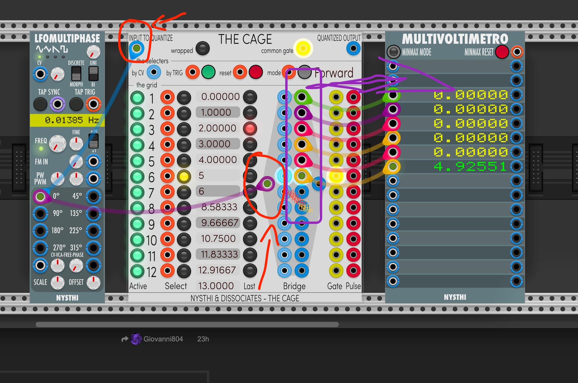
In the meanwhile I tried again with TheCage and stopped when I finally realized that’s more a scale quantization tool, and even after changing the thresholds, I could not make the address work correctly.

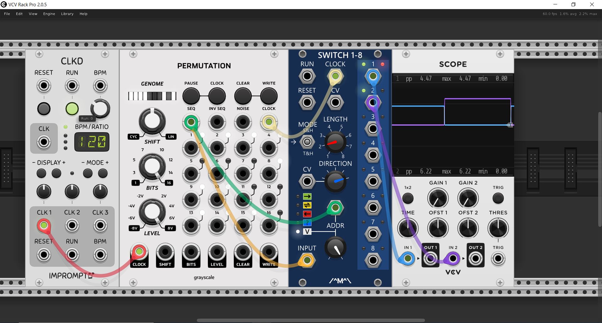
Then I went back to CM Switch 1-8, and made it work! Although it is still a linear split, therefore I’ll dive to read more carefully your suggestions, to explore non-linear ones.

Anyway, working on your previous suggestion of scaling the address cv, I realized that it could be done on the switch itself, by fiddling with the address knob, and leaving the number of steps to max.

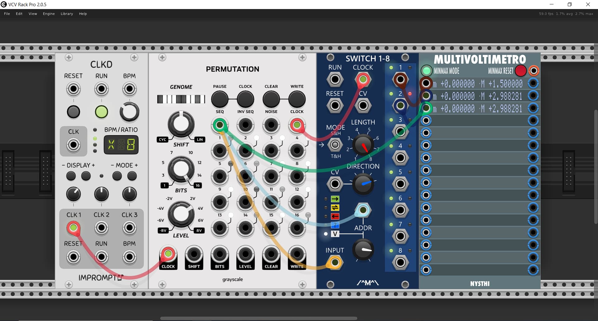
On the Perm I have 0-3v in output, and I tweaked the address knob, with the help of @synthi Multivoltimetro (Thank you! I love the Min-Max function, it was crucial!) until I found the split I liked.

If I change the output range of the Perm, I have to repeat the process to find the new split. If the out max is 8v, the address knob goes to 3.1 (strange value…), for 3v is 8.3

I started first with the idea of the octave split, but the nonlinear sounds more fun.

I also learned the lesson of having to use gates for the output CVs, or when they drop to 0v I get an unexpected note.

Back to one of your comments, what do you suggest I should use to map the output of Perm to either log, exp, or any crazy function, why not? In a VST I just draw a curve on a keyboard and voila’ it’s done, but in VCV/Eurorack?

1 Like

MindMeld ShapeMaster is great for mapping voltage and has presets included for lin to log/exp conversion or you can just draw in any shape you want. (You need to be in CV playhead mode). This time stamped video shows how to do it.

2 Likes

Words of true

here an example of what you want using `thecage"

the LFO is generating a sinusoid going slowly from +0 to +5 v

the output is connected to the “QUANTIZE INPUT”

the output is ALSO set to the “SWITCH 1 to 12” INPUT

the CAGES are set by octaves (0V, 1V, 2, till 13v…)
You must have consecutive CAGES limits for the expected results!

In violet the OUTPUTs of the “SWITCH 1 to 12” connected to a multivoltimetro to demonstrate the correct “caging” (you can use instead your different quantizer and MORE: you can activate them using the current GATE or PULSE activated in the CAGE)

4 Likes