Any idea? ML Sequencer controlled switching back and forth with "first" trigger

hello, i want to switch between forward and backward clock in my Analog sequencer from ML. currently i patch it with a bogaudio switch, the gate is mapped to a latched patchmaster button. now i want to switch only, if the “first” trigger of the sequencer fires. my idea is to combine the two triggers or use one as arming. is it better to use a flipflop or the armed buffer from ML? which flipflop should i use?

logic and seems not to work, because one trigger is latched, the other pushed.

any ideas?

Not sure I fully understand your setup, but I occasionally use the flip flop variants by Count Modula (VCV Library).

Also, perhaps the Logic (VCV) module could be handy here.

If you’re looking to have a one-shot style gate signal you can use an SR Flip Flop with the trigger connected to the Set Input. The flip flop output will go high on the first trigger and will never change again unless you deliberately reset it using the Reset input.

1 Like

i will explain it a more in depth. the ml sequencer has an input for clock forward and backward. you can switch between whereever you want and the sequencer runs forward or backward. now i want to use the trigger first signal from the sequencer. this trigger is fired before the first step, so all is synced for the first step. i use a latched 2->1 switch from bogaudio. here i use the gate to switch. on press on a patchmaster button switches to high and the next to low. how could i syncronize it with the first trigger from the sequencer. as far as i think, it is a kind of AND logic, but one is latched and one is a trigger. therefore i think about an armed buffer or anythink like this.

thank you, i wrote a clarification about my idea. the flipflop you mentioned is not exacly the one i need. i will look for your flipflops.

Perhaps first increase the length of the trigger by increasing the gate length (e.g. with Gates module by VCV), then feed both into a Boolean AND?

The ML Trigger Buffer might work too, but it would be easier to look at a model patch of what you are trying to do.

Now, unfortunately I do not have the ML Analog Sequencer, but maybe you can modify the patch e.g. by using JW’s Grid Sequencer, which also can be controlled forward and backward with separate trigger inputs.

Ah OK, then you need D Flip Flop. Connect the latched switch to the D input and the trigger into the clock input. Whatever gate signal is presented at the D input at the time of the trigger will be propagated to the output and held until the next trigger comes along at which point whatever gate signal is present at the D input will be sent to the output.

You could also use a sample & hold to achieve the same effect.

1 Like

hello, unfortunately i can’t make it work :frowning: therefore i upload a testpatch. forward and backward is working if the patchmaster button is pushed. but how could i sync it with the “first” trigger of the sequencer?

ML Sequencer Test.vcv (2.4 KB)

Maybe this way.

Clock>divided by 16>Gates to shorten binary pulse to approx first beat>CV input VCA

trigger sequencer> input of VCA> ML trigger buffer IN input

patchmaster gate> ML trigger buffer ARM

Since I do not have the ML Analog Sequencer, I drafted a patch with CV funk’s Decima. Maybe this will at least inspire you for your own setup.

The Decima sequencer changes direction according to the DIR input: If input is <=0, the sequencer runs forward, if input is >0, it runs backward.

In this patch, direction changes whenever the sequencer reaches the first step AND there is a clock pulse. VCV’s Sequential Switch 4-1 is used to deliver either 0V or 10V to the Decima DIR port.

Hope this helps in some way.

Decima_20250808.vcv (2.7 KB)

Maybe this will get you closer to what you want

I replaced the “Sickocell Switcher” with tne “ML Sequential Switch 1 to 8” and used the First and Last triggers on the “ML Analogue Sequencer” to ping-pong the sequencer. Also changed the ML Sequential Switcher Output mode to last.

ML Sequencer Test2.vcv (2.5 KB)

So the ML Sequencer has independent trigger inputs to go forward, or backward, or to a random step. But I gather you want the ability to step in a ping pong manner.

So for example, if you are only using steps 1 through 4, then you want the sequence to be
1, 2, 3, 4, 3, 2, 1, 2, 3, 4, 3, 2, 1, . . . . etc.

I believe @scook has some elements correct. But I see some potential problems (I don’t have the ML Sequencer, so I can’t test)

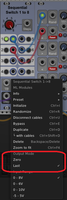
  • I am pretty sure the Sequential Switch output mode should be set to 0, not last
  • If the Sequential Switch is always triggered if either the sequencer First or Last gate is fired, then the sequencer could potentially oscillate between the first and last steps without ever going through the steps in between. To prevent that you only want the First gate to trigger the switch when the sequencer is currently stepping backward, and the Last gate to trigger the switch only when stepping forward.
  • If the switch is triggered while the clock is still high, then the last (or first) switch will not go to completion because as soon as the switch changes, the clock will be sent to the opposite direction trigger and the last (or first) step will immediately exit.

Again, I computed all the above simply by running the logic through my head - I could not actually test anything. So I may have gotten something wrong.

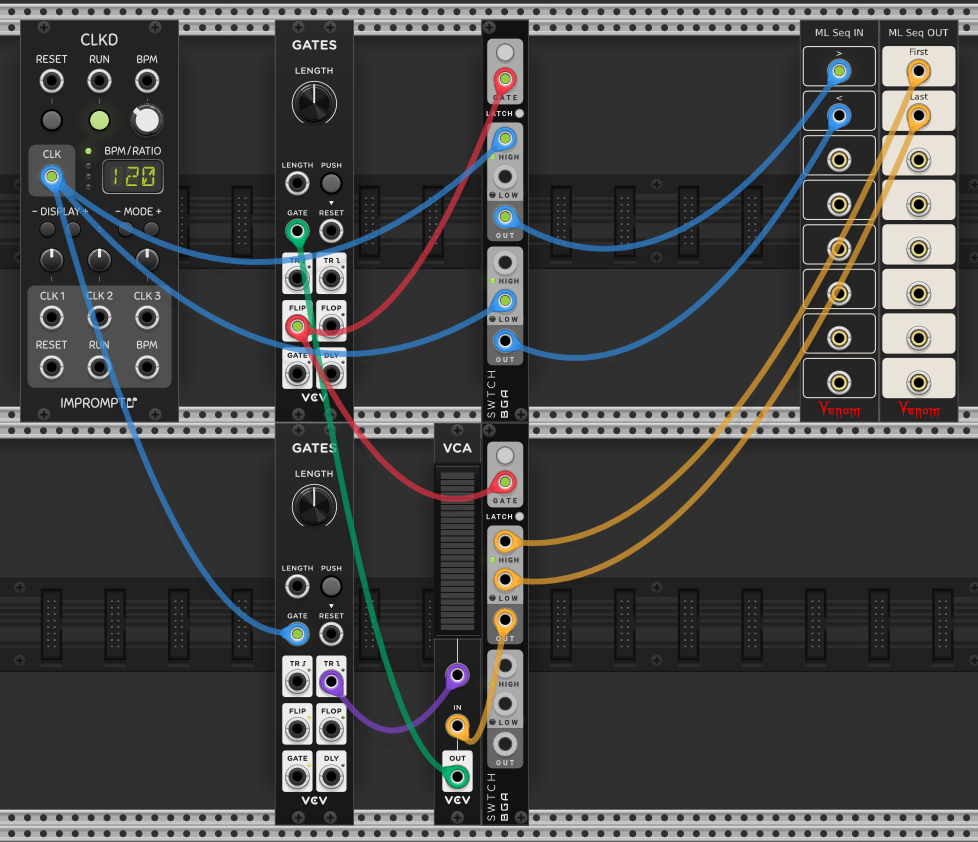
Either way, I believe the following will give the behavior you seek. In the image I am using the Bay Input and Output modules to represent the critical ML Sequencer inputs and outputs needed to implement the ping pong.

The top VCV GATES is operating as a flip flop to control the current direction state. When FLIP is high it represents a forward state, and when low then a backward state.

The top Bogaudio switch directs the triggering clock to the correct ML Sequencer trigger input, either forward or backward, depending on the flip flop state.

The ML Sequencer First and Last gates indirectly trigger the flip flop to change state. The bottom Bogaudio Switch controls which one is active. If currently moving forward, then only the Last gate matters. If moving backward, then the First gate matters.

But we don’t want the flip flop to change state while the triggering clock is still high. So the bottom VCV GATES converts the trailing edge of the clock gate into a trigger. The First or Last gate is only passed to the flip flop trigger when the clock trailing edge trigger AND First/Last gate are both high. So the VCA is functioning as an AND gate.

So lets say we are currently moving forward. Each time the clock fires, the gate is passed to the forward trigger input, and the sequencer moves to the next step. When the sequencer reaches the last step, the Last gate goes high. However, the clock is still high, so the flip flop is not yet triggered. When the clock goes low, the falling edge trigger is fired while the Last gate is still high, and the trigger is sent to the flip flop to change to a reverse state. But now the clock is still low, so the sequencer remains on the last step. Then on the next clock, the gate is sent to the backward trigger, and the sequencer starts running in reverse. The logic is similar once the sequencer reaches the First step so the flip flop reverses back to forward again.

I am pretty confident the above arrangement will work, unless I have misinterpreted your end goal.

1 Like

thank you all for the ideas!

perhaps one thing i don’t mention clear enough: the first trigger output fires before the first step and the last trigger fires after the last step. this is described in the documentation.

finally i managed it with the trigger buffer module from ml, like @cubistguitar suggested. thank you.

unfourtunately another problem remains. because my whole patch consists of two independent and ussually synchronised lanes, after jumping bwd fwd they are not synced anymore. i believe it has to do with the phasors. i will investigate.

If synced Phasor is important for your patch, then I suggest using a diff sequencer that can move by cv like a Phasor. Then make all the change in direction by reversing(inverting) the phasor driving the sequencer.

yes i’m a big fan of phasors. already use phasor and cv based sequencers in my patch. about ten addr-seq and some from hettrick. but the ml sequencer is so feature packed for me, i found no other. so i bought it. before that i already had this out-of-sync problem. @trickyflemming mentioned it in another thread. it seems that using two phasor generator keep in sync is difficult,especially when manipulate steplength, reverse and so on. there was always some synctime for the phasors between the switching. will investigate deeper, because i like the possibilities.

Maybe that is how it works, but it certainly is not described like that in the manual.

To me that sounds like the First and Last outputs are gates that are high for the length of the corresponding step. That also appears to be what happens when I watch the video tutorial.

i watched the tutorial video again and i must day, you are right. dont know, why i thought it was different. but unfortunately it is not an eoc trigger.

i see that your idea respects the falling gate after last step. will check your idea in the evening.

If both lanes always get the same forward or backward triggers, then I don’t see how they could possibly get out of sync. But if one lane goes forward while the other goes backward, and then you switch back to both going the same direction, then I would expect them to be out of sync until you perform a reset on at least one of them.

Maybe I don’t understand what it is you are trying to do.

no you are right. let run one lane continuously forward and the other intentional during jamming forward,backward let them go out of sync. i have to reset both. for convenience and fun i want to find a way that both phasors go in sync after perhaps a cycle. i believe i have to use the second phasor to reset the first phasor and vice versa. meaning if phasor b reaches the end or start then phasor a has to be reset. as far as i understand, then they will be in sync.