I’m really looking forward to this. It’s a very familiar oscillator. I think you have done something very beautiful in terms of graphic design, too.
1 Like
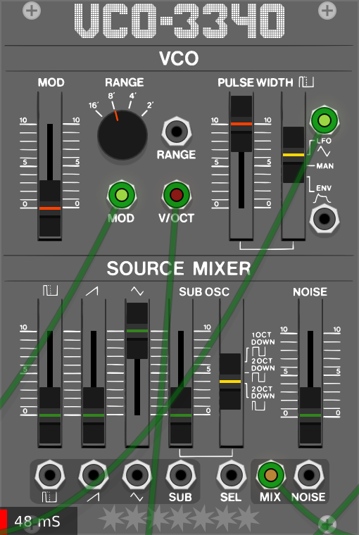
Awesome! Love some 101 flavour in my electronic soup.
awesome
I had been looking a way to connect my nanoloop to vcv rack
I hope it will be available soon
Right. Now I see that my sentence may sound like an accusation (which is not).
What I meant is: “remove anything that could be consider a trademark”.
2 Likes
Sounds wonderful. Nice work!
Update: Just fixed the remaining bugs. Everything should be ok now except for the drift of the triangle wave when PWM is applied (morphs between triangle and saw). I think a correction term based on the phase change gradient should work.
1 Like
I am really looking forward to this!
Out of curiosity, where did you learn to do analogue modeling from?
I’ve been looking in to figuring it out, though currently just looking at charts and basic electronics pages.
I read some papers, e.g. https://ccrma.stanford.edu/~stilti/papers/blit.pdf or https://www.cs.cmu.edu/~eli/papers/icmc01-hardsync.pdf to get an overview over common methods and their advantages/disadvantages. It certainly helps to have a background in maths, digital signal processing and software development because they often assume that you know DSP basics (stuff like “what is a Dirac impulse?”). I have also been developping DSP algorithms for more than 10 years, although they focus on high quality non-realtime processing. The realtime aspect is what is new to me.
Regarding the VCO-101 module, I came up with my own algorithm. I studied the original sound, powering the SH-101 with a high quality lab PSU (makes a big difference!) and recording at the highest possible sample rate (192kHz). Then I tried to decompose the original waveforms into the functions and processes that produce them. Since the waveforms can be interpreted as integrated, they can be differentiated in order to get the impulse train. Turns out that the bandwidth of 96kHz provided by a sample rate of 192kHz is more than sufficient to capture the entire original SH impulse. The next task is to fit this impulse by a bandlimited function that should be strongly localized in the time domain (= it should be as short as possible). Turns out that at 192kHz a 8 sample wide Blackman Harris kernel, integrated with a leaky integrator a leakage parameter of 0,27 does the job very well. This really cool, because 8 samples @192kHz is very short (42 nanoseconds! Translate: Short=efficient), and the full impulse can be calculated ba a simple leaky integration. Next, you need to generate the impulse trains and integrate again using a leaky integrator. Finally, I tried to implement sufficiently fast realtime sinc interpolation which - to my surprise - went well, too. In theory, this is the best anti aliasing method you can use but not the fastest.
One day I write a paper about the full process 
6 Likes
I had an idea regarding this GUI/Roland IP infringement avoidance issue: Provide multiple skins: “classic style” skins in gray, blue and red and a new one that looks very different. The new skin is the standard skin. In order to get the “classic” look, the user has to move the SVG files around. This way it is guaranteed that no user can be fooled into thinking that the plugin is a Roland product because a (minimal) action on behalf of the user is required to use a “classic” skin.
1 Like
Thanks, let’s hope good old Roland does not give me too hard a time:-)
IANAL, but if you make and distribute the skins as a single package that won’t fly. Renaming the files doesn’t get you out of lawyers up the butt.
I don’t know if Arguru’s sinc made it anywhere public. Renoise has it and there were some tests that it was good, but it’s very much not real time.
@skins: Thanks. I wouldn’t mind separating the plugins package and the “classic” SVG files.
@sinc: I am using a sinc kernel with 7 zero crossings, windowed by another sinc kernel with one zero crossing. Values are precomputed in a 10000X oversampled lookup table and chosen by next neighbour interpolation (fastest). VCO-101 runs 5 sinc interpolators (one each for pulse, saw, triangle, sub oscillator and noise). The cost on my 2009 I7 920 PC is around 30 millisampes. No audible and little visible (spectrogram) aliasing as far as I have seen so far.
P.S.: Just checked: At 44.1kHz the cost is lower. The entire VCO-101 uses around 40 millisamples.
1 Like
Not sure if your approach is what’s usually called “analog modelling” (I assumed that would rather be SPICE-like circuit modelling, I might be wrong though), but very nice learning about your approach and how you tackled the DSP issues. Would love to read more posts like this. I’ve been out of the DSP game for a couple of years now, but looking forward to get back into it.
@Analog modeling:
I used SPICE last year when I was interested in studying VCFs. Took several minutes to calculate a few seconds of a Moog style ladder filter sweep. I guess (I do not claim to be an expert) the problem with this kind of modelling - I call it simulation - is that you usually have to evaluate a rather large system of (differential) equations that describes your circuit at very small time steps for good and stable results. Therefore the ratio effort/result is usually prohibitive for realtime applications. UNLESS you use hardware that can do parallel evaluations at high sample rates efficiently, like FPGAs (https://ieeexplore.ieee.org/document/7981562). In think this is how the Roland boutique synths or the Novation peak do it.
Another kind of modelling (let’s call it signal reconstruction) attempts to model the output of a circuit instead of the behaviour of its components. The assumption is that compared to simulation the interesting part of the behaviour of the circuit (here: The output/sound) can be represented by a much simpler/cheaper mathematical model. Not having to calculate things that you are not directly interested in, this method is much more efficient than simulation.
The important question is: What about sound quality from a musical perspective? What are the challenges?
- Simulation approximates a natural process. A rough (computationally cheap, e.g. through larger time steps) model tends to yield a rough approximation of the desired output. Unfortunately it is the details that make a sound musically expressive. So, you should either be able to calculate detailed models efficiently (=> FPGAs!) or not go for simulation modelling.
- Signal reconstruction: Here the result can be as good as the signal can be described by its model. There are deterministic and stochastic components. Fortunately, with analog VCOs, the processes that created the analog signal are relatively simple (compared to e.g. acoustical instruments). Therefore, one can expect that there are a few simple functions that can be used to describe it, including its details.
Summary of what I have learnt:
- VCOs: You can use simulation on specialized hardware but on standard PC CPUs the way to go for efficient calculation of detailed signals is the signal reconstruction method.
- VCFs: Here, simulation tends to yield better results because it is difficult to describe the nonlinear properties by just looking at the signal (see e.g. http://ita.ucsd.edu/workshop/06/talks/papers/55.pdf). Still, I am not convinced that currently simulation can yield results with comparable musical expressivity because simulation tends to focus on dominant components and omit small details. I guess that is why Novation decided to use FPGA based oscillators but real analog filters for the Peak. It is also (among others) a reason why I am not the biggest fan of the boutique synths.
Caveat: I am relatively new to real time DSP and still need to learn a lot
3 Likes
Most of the Vult filters fall into the category of simulations. My process consist on creating simulation models of the circuits then creating custom simulators to run the systems of nonlinear differential equations derived from the circuit. As highcarbschwabe mentions above, this kind of simulation is computationally expensive. But I have managed to run my models at a very competitive performance and capturing good level of details.
2 Likes
I must say that the Vult plugins I have aready tried are awesome indeed!
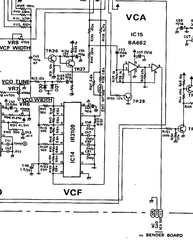
I don’t see any problem with converting the SH-101 into VCV Rack plugins - except for the VCF! If I recall it correctly, the IR3109 is based on LM13700s and the entire circuit does not look too complicated (see below), so it should be possible to figure out its mathematical representation.
But could you please elaborate on how you get good/stable results at (relatively) large time steps? That did not work too well when I experimented with SPICE… Or have you found a way to decrease the cost per time step so that you can run your model at small time steps? Thanks!
I haven’t modeled this circuit but looks to me like a ladder filter that tried to avoid the Moog patent by using the transconductance operational amplifiers as controlled resistors rather than a diode.
The maximum step size depends on the dynamics of the circuit. When simulated (or discretized) the maximum step size that you can give depends on many factors. One is the fact that the resulting discrete system is unstable with poles outside the unit circle. The nonlinear behavior makes it more complex to calculate analytically the stability. Other reason for the instability could be that the system is stiff. Sometimes the problem can be reduced by using model order reduction techniques. In one of my most complex models (Vult Vortex) the only thing that has helped is to write a very custom and optimized simulator for the circuit and try to minimize the number of computations.
Having said that. Sometimes it does not worth doing all the extra effort to get a marginal gain. I have a video where I talked more about the topic:
2 Likes
Thanks a lot! The vortex sounds AMAZING btw!
So, as I take it, there is no general optimization method but you rather have to look carefully at each circuit and find out what it allows you to do, right?