Venom VCO aliasing issues

I could use some help fixing some aliasing problems with my Venom VCO (derived from 21kHz Palm Loop). I’ll describe the issues toward the end. But first I want to give some background.

The reason I am interested in creating a new VCO using the Palm Loop VCO as a starting point is because it does a good job with anti-aliasing without obvious distortions at the discontinuities. This allows me to more effectively use it as audio rate CV with clean waveforms, while still being used as anti aliased audio at the same time.

The other point of interest is its ability to do true linear through zero FM (not phase modulation). With a bit of work it can also be used as a 0 Hz carrier wave. I have done a bunch of comparisons with different VCOs that can also do 0 Hz carrier wave through 0 linear FM, and was a bit surprised that all the other modules I looked at have aliasing and/or other issues when outputting negative frequencies.

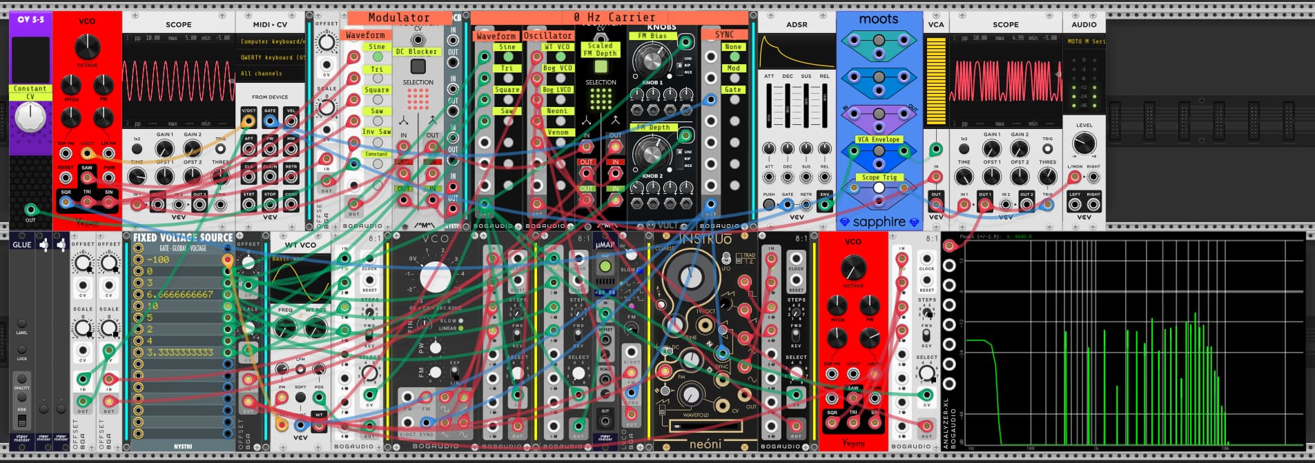
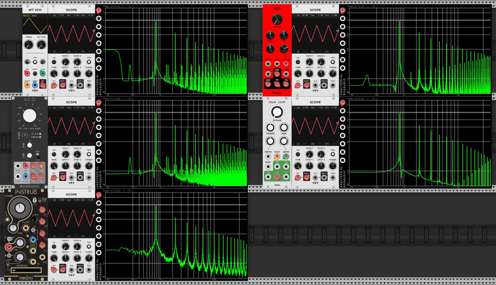
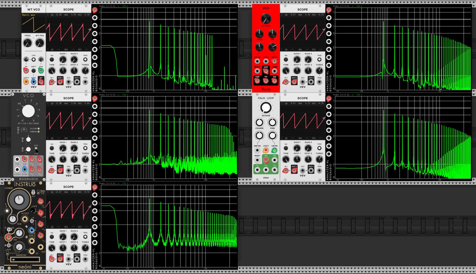
Below is a series of frequency plots showing the issues, and why I am so intrigued with the Palm Loop. All the VCOs are configured to be in a 0 Hz carrier wave mode, each being supplied a constant CV input at the linear FM input. I had to do a bunch of calibration so that they all produce the same frequency (more or less) as I sweep the master CV control. The amplitudes are all at -120dB so it is easier to see the aliasing, even when mostly inaudible.

Sine Wave Positive FM input

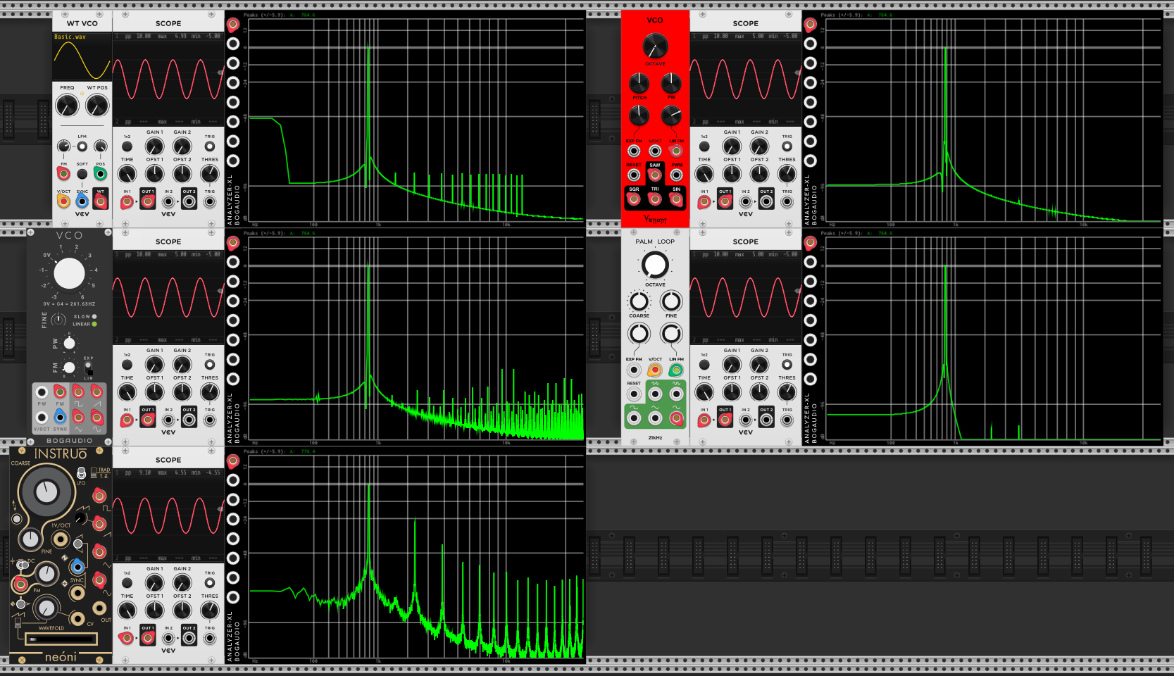
Sine Wave Negative FM input

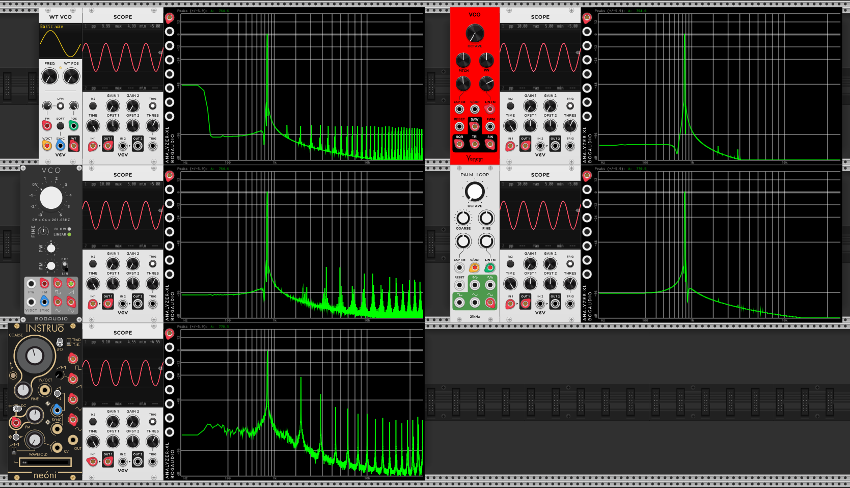
Triangle Wave Positive FM input

Triangle Wave Negative input

Square Wave Positive input

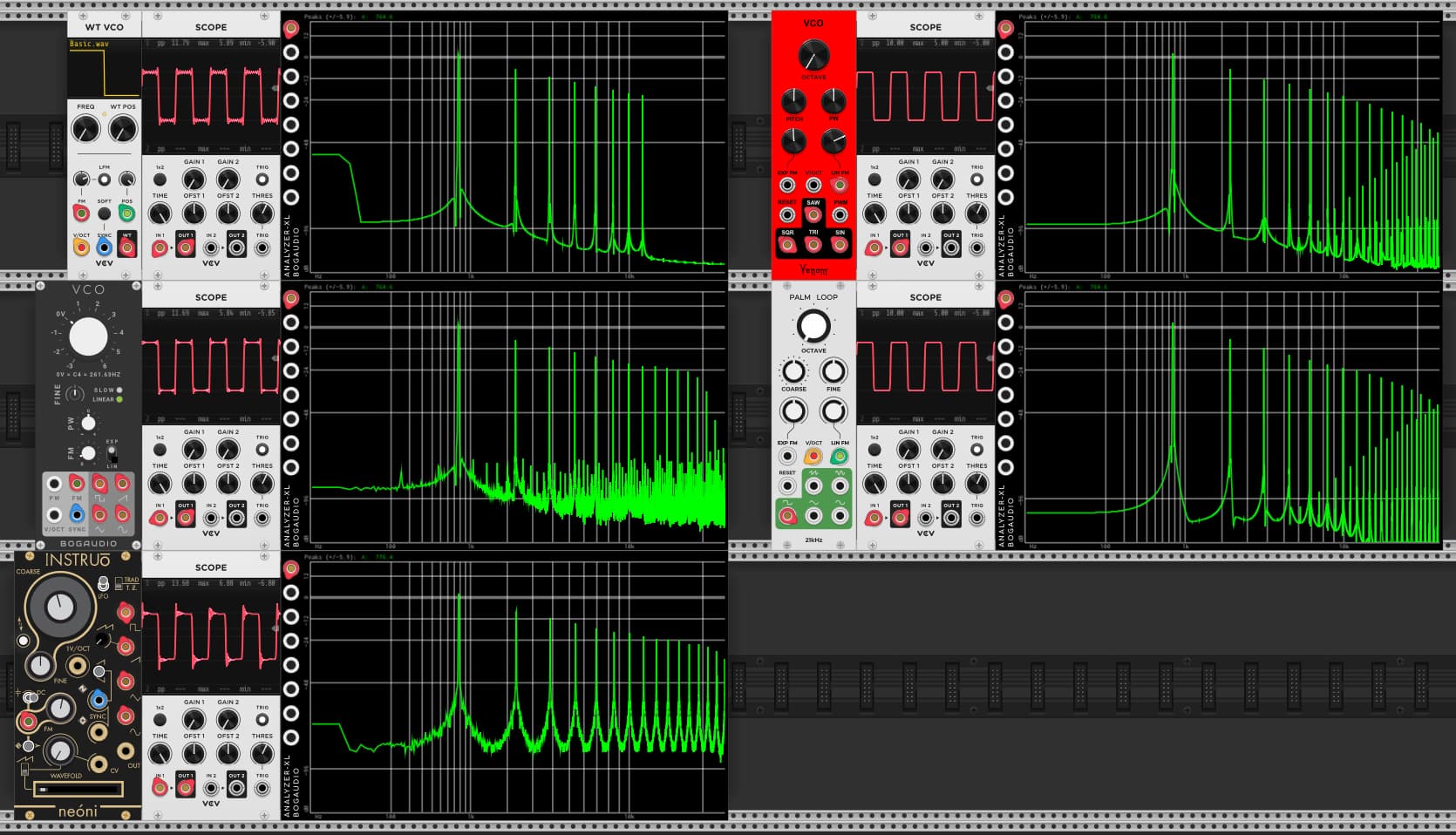
Square Wave Negative input

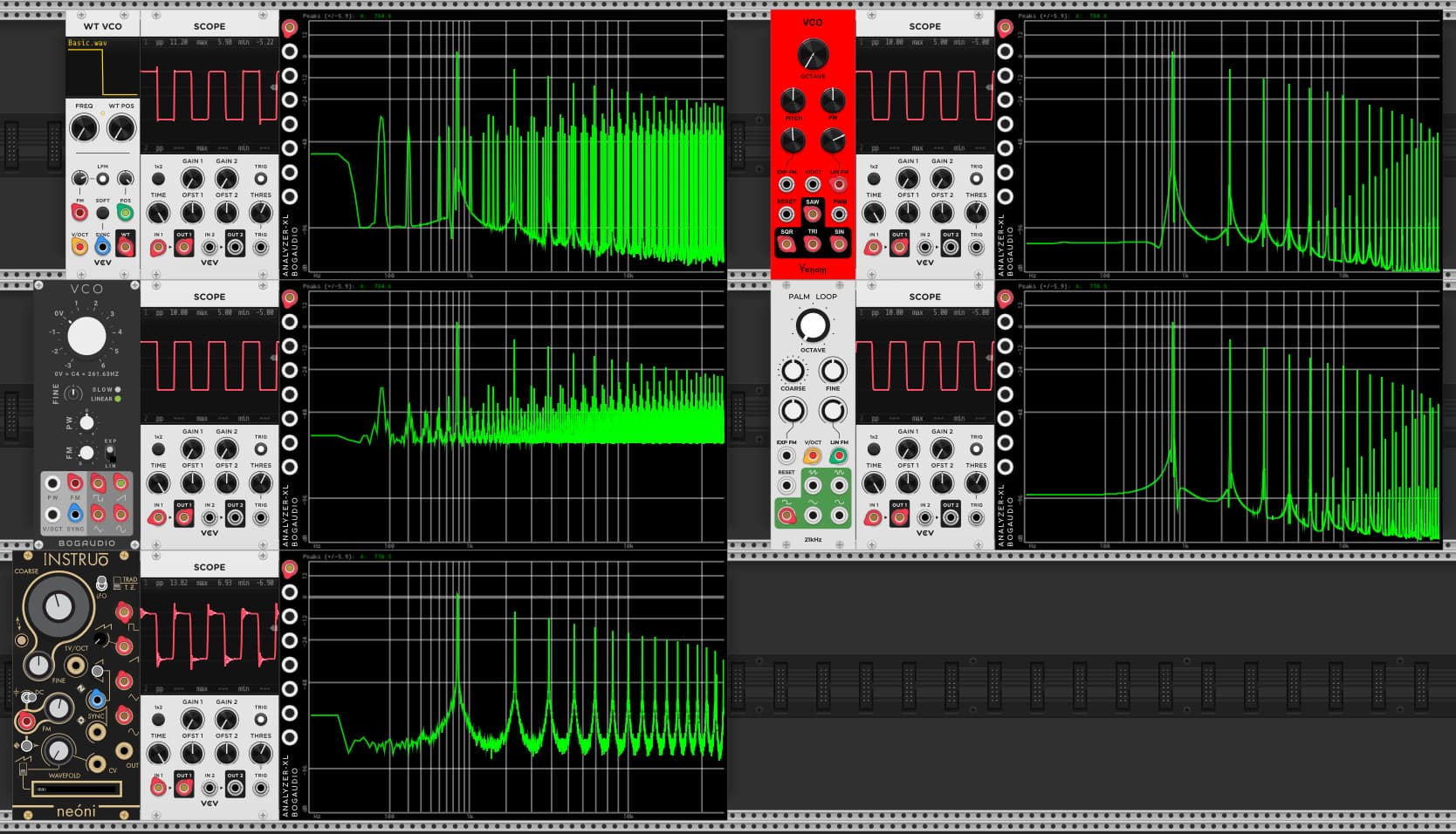
Saw Wave Positive input

Saw Wave Negative input

The Palm Loop consistently looks very clean, both in the scope, and the analyzer. It certainly has aliasing, but it manages to keep all of the aliasing in the high frequency range. It folds at the Nyquist frequency as expected, but then on the return reflection it folds forward at a high frequency, unlike most that fold forward at 0 Hz.

My Venom adaptation mostly preserves the Palm Loop behavior, except it aliases the negative triangle frequencies :frowning: The really fine looking negative saw wave is an artifact of being slightly out of tune compared to the Palm Loop. The high frequency aliasing is there, but it just happens to coincide with other partials in the wave form.

The Neoni looks decent as far as aliasing, but the signal is very dirty and harsh when compared to the others (especially when listening). It also has a number of oddities that show up when doing actual FM.

The VCV and Bogaudio clearly have significant aliasing issues in the negative range, although sine is not bad. You can see how the saw waves flip when in the negative region. But the Bogaudio negative saw is offset to be unipolar.

The things I don’t like about the Palm Loop are

  • the triangle and square are 1 octave down - this is an inherent result of the algorithm used.
  • Not shown, but it has some sync issues with the sub octaves
  • It is not polyphonic
  • No pulse square wave pulse width modulation

I wanted to address those issues with my Venom VCO. I’m not going to address polyphony until I resolve other issues. It seems like I am close, but I am worried about the aliasing problem. I have no idea how to fix it.

Besides aliasing with the negative triangle, it also explodes with triangle aliasing once the frequency rises above ~ 1/4 Nyquist frequency.

I have also implemented pulse width modulation, and attempted to eliminate DC offset, but the moment it strays from 50% duty cycle there is a ton of aliasing, and also DC offset. I think the DC is from the aliasing, but I am not sure.

The saw and sine are working great. And the square is fine as long as I stay at 50% duty cycle.

Below is a video that shows both problems.

I’d love if someone with some DSP skills could look into this.

My code is at GitHub - DaveBenham/VenomModules: Venom VCV Rack Modules

And Palm Loop code is at GitHub - netboy3/21kHz-rack-plugins: Modules for VCV Rack

I don’t understand what you mean by “positive FM input” and “negative FM input”. I don’t know what I’m seeing here.

One thing stands out to me is that the pulse only works at 50%. As you know from my previous rants, most pulse wave outputs put out a huge amount of DC when they are at anything but 50%. With FM, as opposed to PM, that will drive it out of tune.

Back when I had a public github I had published a lot of data about this.

I also don’t get why you are - is “obsessed” to strong a word? - with FM vs PM. They are pretty similar, and mathematically closely related…

for example, here’s a simple “patch” where VCV fundamental is outputting a triangle at C5. Kitchen sink is the carrier, and is set for a wavefolder output and tuned to C7.

You can see the output looks nice and clean, even with a huge amount of phase modulate, which is mathematically exactly the same as a truly enormous amount of FM with a square wave modulator.

I will confess that when I used the square wave output of Fundamental 1 to drive the “LFM” input of Kitchen sink that the output is quite dirty - possibly the aliasing you talk about. The anti-aliasing in Kitchen sink is “just” 4X oversampling, so I can easily see that driving it with a pulse wave would cause it to alias. That is perhaps a flaw in that venerable VCO.

BUT - this (to me) shows that a VCO that’s designed for through zero linear phase modulation (or FM) can easily handle negative frequencies.

When we were discussing Bogaudio before I assumed you were talking about the FM-OP. Clearly you were using one of their other VCOs - I don’t know much about them.

And, of course, there are very few VCOs designed for FM that let you set them to zero frequency carrier. But that doesn’t mean that they aren’t doing through zero FM.

and, of course, to beat a dead horse, it is well known that Fundamental-1, while it did add linear FM in version 2.0, it has a couple of limitation. 1) it has no alias suppression at all, 2) it intentionally clips the negative frequencies which can make it quite dirty when driving hard:

All VCOs are set to 0 Hz (or nearly 0, some have some residual bias)

So a constant positive FM input yields a constant positive frequency, and a constant negative FM input yields a constant negative frequency. I am not interested in using constant FM input as an end result, just as as a tool to investigate the characteristics of the underlying waveform before frequency modulation is applied.

I don’t see a need for a new VCO that performs phase modulation - I think there are plenty of excellent options out there. But the options for true FM are limited, and I think there is room for improvement, at least from the standpoint of minimizing aliasing. Yes, PM and FM are closely related, but there are distinct differences as well - things to be explored with FM that cannot be done with PM, and perhaps exploit those differences for sound design or music production.

I don’t think a pulse wave modulator makes sense for PM if you are trying to get something that is related to FM. A constant voltage PM input of course has no effect. Using a pulse wave just alternates between two “constant” values. Conceptually it seems the result should be similar to a hard sync that alternates between two different phase points.

Pulse wave modulation is one of the avenues I am interested in exploring when it comes to true FM.

Here is a patch that I use to explore 0 Hz carrier true FM - a special case of FM that I find interesting due to the symmetry involved.

FM 0 Hz Experiment Venom.vcv (14.9 KB)

There is a lot to explore in the patch, but I don’t have time to write it all up properly or prepare a video. Hopefully Glue labels are enough for you to figure things out. The intent is to restrict manipulation to only modules that are labeled. The patch lets you choose what waveform to use as modulator, and what VCO and waveform to use as carrier. There is also an option for a constant voltage “modulator”. You can also control the depth of modulation, and the amount of FM bias (distance away from true 0 for the carrier). Change pitch with computer keyboard. Activate MOOTS VCA Envelope if you don’t want constant sound. Deactivate scope trig if exploring constant CV modulation. Scaled FM Depth attempts to even out the amount of wave folding across all carrier frequencies. Carrier (hard) Sync options are there. Lastly activate/deactivate DC Blocker to explore the effect of carrier DC. Disable the square wave DC Offset correction on the Bogaudio VCO with context menu, and choose Bog square for your carrier and modulate PW if you want to explore effect of DC.

1 Like

Ah, interesting. It occurred to me that it would be pretty easy for you to fork an existing module that does “good” PM and modify it so that a) it’s FM instead, and b) can easily be set to 0 hz. It would be quite “easy” to do this with FM-OP or Kitchen Sink. If you were interested in doing it to Kitchen Sink I would be happy to help.

I can’t imagine how to convert PM to FM, but if you can do it and get good anti-aliased results for negative frequencies, I am definitely interested. I think the simplest test for success is to be able to apply constant CV to the linear FM input and get a good anti aliased constant frequency output for both positive and negative frequencies. That alone doesn’t guarantee “good” FM output, but it seems like a necessary starting point.

I thought it was easier to start with an existing true FM VCO that can already produce anti-aliased negative frequencies like Palm Loop. My adaptation is just failing in a couple cases. I have not investigated oversampling, other than verifying that running at higher VCV engine sample rates definitely improves things. So maybe oversampling is all that is needed, though I expect that is more CPU intensive than the polyBLEP, polyBLAMP that Palm Loop uses (assuming all are equally optimized with simd). I think I have a vague understanding of how oversampling works, but not enough to be able to code it - I would have to study some other existing code and try to digest what is going on.

Also, I’m not sure oversampling would produce the same “clean” waveforms around discontinuities that I see with Palm Loop. I have other projects where I think this trait helps, though I can’t be sure until I get an oscillator that can produce all 4 basic wave forms at the same frequency with proper hard sync capabilities.

Actually, I don’t see how FM-OP or kitchen Sink helps, even if you do manage to convert PM into FM.

I am looking for all four basic wave forms: Sine, Triangle, Square, Saw

As far as I know, oversampling is the only way to clean up FM/PM. Most of my modules using minBlep, but Kitchen sink (and FM-OP) use over-sampling.

I’d be happy to throw something together if you have time to play with it.

btw: what is it that you don’t like about minBLEP vcos like Fundamental VCO or most of mine (or Even VCO or almost any of them)? It’s true the waveforms look weird, but they look awfully clean on the spectrum analyzer.

Kitchen sink has sine, of course. It also can output a waveform that morphs from triangle to saw, so those two are already covered. (Unlike FM-OP which only has sine out, I think).

Anyway, I’d be happy to do the PM → FM conversion and a zero hz option. If you are interested, we could try that.

But if you are not interested in this of course I wouldn’t do it. Or if you can trivially reject the idea based on not likening the sound of Kitchen Sink in general, that would also be a reason not to try that.

And, yes, oversampling uses more CPU. That’s probably one of the reasons Fundamental switched from oversampling to minBLEP in the update from 0.6 to 1.0. But if you need it… My “Shaper” has three user settings for oversampling, as does “Saws”. Some super clever ppl here may have more efficient ways to eliminate aliasing in cases where you can’t use minBLEP - I’ve seen some interesting stuff kicking around that frankly I don’t understand.

I am trying to have my cake and eat it too.

One example is in my attempt to emulate the Sophia Eurorack module from XAOS. I try to use the square and sine from one polyphonic VCO as audio, but also use square and saw from the same VCO as CV to apply to a VCA (saw as an envelope, square as a switch) The “oddities” around discontinuities interfere with timing and amplitude, and add jitteriness and harshness to the result.

Absolutely I am interested. And of course I have no problem with the sounds of your VCOs.

haha, tx. With any luck I can knock out something to play with soon (in the next couple of days). I’ll let you know.

1 Like

@hemmer was also working against aliasing when building a TZFM oscillator a while ago, maybe he could recommend something?

Do you have a low-pass filter at 20khz? That usually helps aliasing at least a little bit.

No. But I don’t see how a filter can help eliminate high frequencies that have been reflected into low frequency audio territory. I didn’t think a filter can detect the frequencies until after the folding (aliasing) occurs, which is too late. Plus the polyBLEP or polyBLAMP is supposed to greatly attenuated the aliasing so that there is little perceived issue. I just have a problem with my adaptation for the triangle, as well as square (pulse) at other than 50%.

Nothing to add beyond the reponses in this thread really - for reference Pony TZFM just oversamples (and makes sure the carrier/mod waves don’t alias to begin!).

Exactly (unfortunately!).

1 Like

My “Basic VCO” has two different options for triangle waves. One is the “naive” implementation with no alias reduction. But of course there isn’t much aliasing in a triangle like that anyway. The other one copies the Even VCO, and it starts with a minBLEP square and then integrates it. That gives a tinny amount of aliasing.

Don’t know if any of that applies to what you are doing.