Here’s a great video from Instruo with some fairly nuts modular sounds:
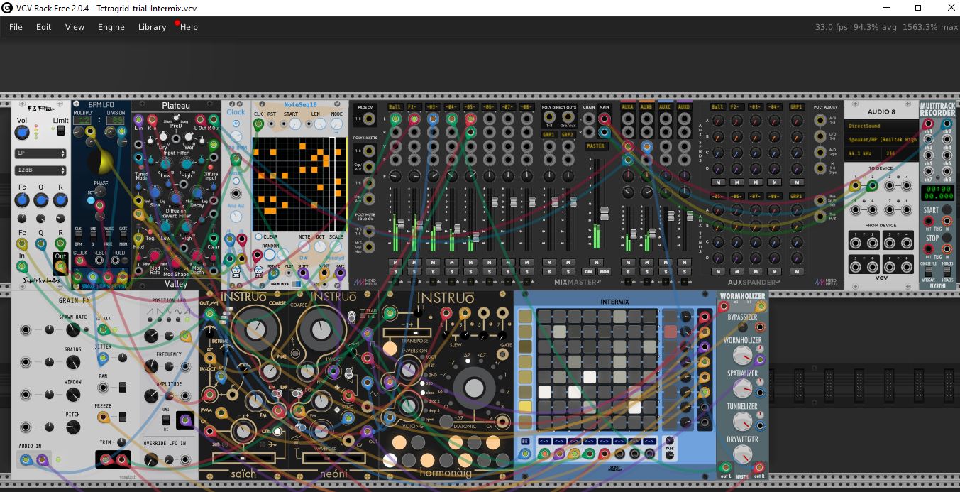
A big part of the patch is the Tetragrid:
The Tetragrid is fundamentally 6 oscillators configured as 6 CV/gate sources. Connecting the triangle touch points on the playing board with magnet pieces or a finger will interconnect modulations between these 6 oscillators. Placing magnets in sweet spots can produce consistent repeating rhythmic gates from the various outputs.
I wondered if we could create something similar in Rack, using a matrix mixer like Intermix.
Just a whacky idea really, haven’t done any work on this yet. Any thoughts?
Well I have used Intermix in the past with loads of FXs and produced unholy racket if I remember correctly! So how would this work then in Rack? So Tetragrid sounds like it is circuit bent then or that’s the concept{?}
You any idea how to start this? Interested to have a go and work with you on this.
Well, I have other projects I want to finish before starting this but…
DISCLAIMER: I have no idea how to actually do it!
I would start with patching six VCOs into Intermix, then looking at all the FM/Sync inputs. Maybe you’d need one Intermix for the audio and another one for mod inputs. You would need to route some feedback in for the FM ideally, and probably some attenuation on that so it doesn’t get out of control. Just a thought at the moment…
Mmmmm…quite hard to get my head around the conceptual workings of this construct of crossmodulating fixed frequency oscillators (yes, two of them can be modulated) in neural network topologies, resulting in this kind of unpredictable and unstable behaviour (but seemingly also states of relative stability).
Even though this oscillators have a fixed frequency ( dictated by the value of the cap ) , just by having 3 or 4 different cell groups you can get ALOOOT of modulation points and generate quite complex rhythms
the beauty of it is that the circuit is not really stable and takes some time to settle down and it glitches on some occasions!
Even and Odd cell groups have different behaviours: even ones are stable, while odd ones tend to feedback resulting in chaotic and ultrasound behaviours.
It might be the behaviour of this system relies on specific physical characteristics of the physical components and connections involved.
Might be the construction and particular ‘oddities’ do not easily (or not at all) translate to the digital modular world of VCV Rack (e.g. where things do not happen ‘instantanious’ and ‘inputs’ cannot be ‘outputs’ at the same time and signals can not spiral out of control into hypersonic territory and back again).
Some time ago I did patch up all inputs and outputs of 4 “FM” operators (including their feedback loops). And then modulated the input/ouput levels (both as ‘modulator’ and/or ‘carrier’) so that it would eventually transition through all permutations (‘algorithms’), and all input/output levels, including all possible feedback loops.
I was sort of expecting to ‘blow up’ some input real soon, but after setting some limits, it would happily run sort-of-smoothly, gradually transistioning from one state to the next.
Yes it would generate FM Noise in case of ‘perfect storms’ (cumulative modulation), but never ‘sudden death’ or some other ‘unrecoverable catastrophe’.
But, I did not (inter)modulate the frequencies (V/Oct) of the individual oscillators in this cross- and selfmodulating network. Maybe that would result in some of the unruly behaviour of the TetraGrid (although based on totally different concepts).
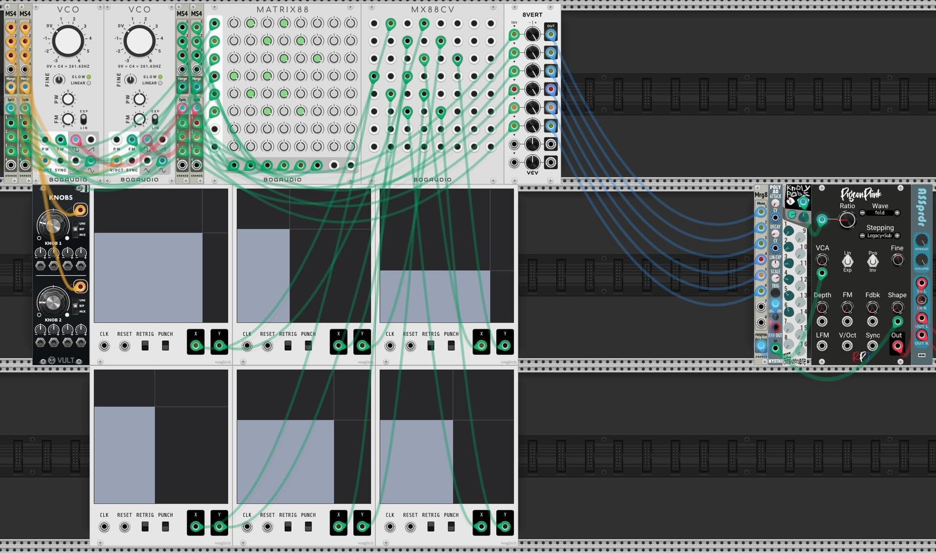
Two VCOs in LFO-Mode - each with 3 channel polyphony - so six different Oscillators.
The general speed of the left one is controlled by knobs upper knob and the right VCO with the lower.
FM-Amounts are controlled by Bogaudios Matrix88. I tried to imitate the magnets with 6 X/Y-Controllers. Those are controlling the FM-Amounts which I assigned in a crossover-style.
Here I am using the Square-Outputs to generate gates, but changing the red cables to another output would result in different waveforms on the 8Vert-Outputs.
I am triggering here just 6 different notes on the pigeon plink, you could use the outputs for whatever you like of course.
I have this feeling that an approximation can be constructed using a crssmodulating FM network. But using a wide modulation range from 0 Hz to as high a frequency as the oscillator used allows for.
In the original concept frequencies could spiral into hypersonic (Mhz or theotically infinity?) range, where it would then be “downsampled” to get it back down into audible audio range (compare: bat detector). Which might be compared to samplerate reduction/aliasing? Aliasing in itself is effectively a divide down of the Nyquist passing frequencies involved (divided by the intended frequency DIV Nyquist, being some integer number).
At least…that is my current understanding…
Anyway…
I don’t yet see how to get a TertraGrid(-ish) neural network working in VCV rack. Even without the added complexity of the dynamic interactions to manipulate the ‘synapses’ in the ‘neural network’.
Intuitively the key element in the solution is in the bit about the behaviour of the even and uneven numbers of ‘neurons’ in a group. Where odd numbered groups end up in a pardoxical/impossible resolving cycle of conflicting states, spiraling out of control. And even numbers tend to resolve to a more stable state.
Just hooked up several LFO’s (squares) and a mixer to…some neural network plugins from NonlinearCircuits. Especially GENiE.
I set up some quick and dirty arbitrary (cross)modulation and feedback loops.
Some LFO’s at various rates to Genie inputs
Genie output(s) to Genie inputs
Genie output(s) to mixer inputs
Genie output(s) to mixer CV (effectively Amplitude Modulating that channel)
Mixer output(s) to Genie input(s)
Some LFO outputs to Mixer input (varying the channel levels).
Some LFO outpust to LFO inputs
Fiddling with mixer sliders, Genie knobs and LFO frequencies and modulation depths sure give you all sorts of sort of stable repeating patterns. Where AM (sum- and difference frequencies) and Feedback can yield very complex and high frequencies at times (aliasing and all). They can go way above the input LFO frequencies which seem to give the best results when ranging from several Hz to some 200 Hz.
After some fiddling results are reminescant of TetraGrid output. On the Oscilloscope the construct even shows non-square (curved) shapes. Just like TetraGrid generates. Even though everything is based on square oscillators (in case of Tetragrid astable multivibrators).
Using submixers (e.g matrix mixer) you can soon create much more complex cross modulating feedback networks with something like GENiE as a central neural processor.
Here I go again, trying out Genie on Instruo Saich and then sending it to Squid Axon. Not sure it sounds anything like the Instruo patch mind.
Not tried Matrix mixer though.
Thanks everyone, some interesting ideas here which I’ll check out when I get a chance. Not sure where the ‘neural network’ came from, my understanding was that basically the Tetragrid was just a kind of patch matrix for cross mod with a funky interface using magnets. However, anything that makes messed up sounds is cool with me!
Yeah, the neural stuff was too “WTF?” for me, and I feared that not watching to the end of the instruo-video was a fault on my side. When I have time I will watch it in full length, my take of the tetra-grid was after watching the first explanation of Jason: “Here are two controls for Speed, and the FM-routing is done with the magnets, and the outputs are essentially gates”.
Nevertheless, my Patch has brought up a few interesting patterns for me.
Basically AlgoMorph ‘just’ routes signals. Which you can use for whatever purpose.
I think AlgoMorph is a brilliant and promising solution to reduce complexity by offering an abstraction layer to manage (and crossfade between) permutations of complex networks.
Internally it support feedback loops (an essential process in TetraGrid). But, you could also create modulation/feedback loops outside of AlgoMorph, from one or more of the outputs back into one or more of the inputs (and optionally insert stuff into the modulation/feedback path).
If you feel limited by AlgoMorph’s 4 x 4 networks and the almost 2000 permutations, you could interconnect multiple instances of AlgoMorph to get (even) more permutations and (even) more complex networks/algorithms.
And yes, many of these routing options are very usefull to setup FM/PM algorithms. Which is otherwise quite a tedious process in modular, using matrix mixers and many cables. Especially as the number of operators and therefore the number algorithm permutations (possible (inter)connections) increases. Also, you will soon lose oversight due to the resulting cable spaghetti. Even for a 4 x 4 network (with some level control for all I/O, vca/env/lfo).
Another fun thing to generate crazy but repetitive (pulse/square) patterns/pitches from is to use PLL.
Cutting loads of corners, a PLL will desperatly try to get and keep in sync with an input signal, using various strategies.
Frozen Wasteland - PhaseLockedLoop
There are many ways to connect this up. But (with TetraGrid in mind) feeding it some LFO rate repetitive pattern and introduce a feedback loop seems to be the fun bit.
E.g.
Setup and mix some SQUARE LFO’s (e.g in whole multiples or powers of 2 ratio’s).
The frequencies and amplitudes determine the ‘repetiveness’ (timing) and ‘frequencies’ (pitch range) generated by the PLL later. So I kept the frequencies pretty low (notes/bars and such, so start with fractions of seconds). Same for the amplitudes (for starters).
Leave 1 mixer channel free. We’re gonna use that for the feedback loop.
Connect the Mixer Main Out to the External IN from the PLL.
Connect the PLL Main OUT (back) into an empty mixer channel. this is our feedbackloop (with amplitude control)
Connect the PLL’s mixer channel OUT back into the PLL Signal IN
The PLL Main OUT and Comparator OUT will sort of sound the same (Square wave patterns of various stepped/slewed frequecies). But the Main OUT is a bipolar signal with a centered offset (like Audio). For the Comparator OUT the offset moves up and down with frequency (fun for CV?).
Since we are in a feedback loop, the Mixer Main OUT and Mixer PLL channel OUT will also sound and behave similar to the PLL OUT’s. The Mixer OUT will be similar to the PLL Comparator OUT (with shifting offset). The Mixer PLL OUT has the PLL Main OUT (centered) offset, since it receives its signal directly from PLL Main OUT.
As you close the PLL Lowpass filter (LPF), this changes the patterns and introduces pitch slew (since the Low Pass filter will not pass the sudden high frequencies resulting from the sudden changes).
The various Comparator types generally have a profound effect on the behaviour (XOR, Flip-Flop, Coincidence, Fuzzy XOR and Fuzzy H XOR)
The output is all sorts of wacky pulse/square patterns.
You can use the centered or the varying offset output as Audio and/or CV signal. E.g. connect it to Gain level of an amp (AM) Or connect it to a V/Oct and/or FM/PM or SYNC of an oscillator (with or without offset change). Or feed it to something as a modulating train of GATE/TRIGGER signals. Or introduce some Logic (since its all pulses/squares).
You can also setup multiple PLL’s in parallel, series or networks…
EDIT…
I forgot about the PLL PWM and PLL VCO Frequency knobs. The PWM…well…determines the pulsewidth. The VCO Frequency has a profound effect on the behaviour in sense of the generated pitches.